Let's look at forging operations in detail, with videos and drawings.
You may need the following links:
- Where to buy a hammer https://fas.st/Jzz1Zf
- Where to buy an anvil https://fas.st/ujTE_
- Where to buy pliers.
- How to make pliers is here, and here is a simplified version from construction ones.
- How to make an anvil with your own hands.
Introduction
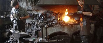
Innovations in the blacksmith's craft concern only the improvement of forging techniques , but the basis has remained unchanged for hundreds of years. As before, the technological processing of metals consists of the mutual sliding of grains, as a result of which they are drawn out; the key point of the process is the direction of grain stretching - along the flow of the metal. In this case, the fibrous nature of the metal is ensured by the stretching of non-metallic inclusions. Due to the high temperature, the metal acquires high mechanical properties as the grain size increases.
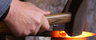
The technique of forging metal involves processing it in a heated state, since high temperature ensures plasticity and pliability of the material. But cold metal processing is not excluded, although it requires additional equipment, while for hot metal processing the main tools are a hammer (hand hammer or mechanical hammer) and an anvil, and for cold forging - special machines and a grinder.
Video: how to hit with a hammer
Strict adherence to the thermal conditions of forging will simplify the work with metal and subtly feel the changes in the plasticity of the metal during the cooling process to give it the desired qualities.
Depending on the type of steel, the length of processing time and the complexity of working with the metal vary. For example, high-carbon steel requires more skill and time than low-carbon steel, which can be worked with longer without reheating .
In addition, high-carbon steel is more difficult to forge due to the temperature conditions during heating and subsequent work with the metal.
Pulling (drawing)
The essence of the operation. Broaching (Drawing) consists of increasing the length of a metal workpiece by reducing the cross-sectional area.
I’ll tell you about the hood and show examples of how it’s done.
Video
Drawing can be aimed at improving the grain structure of the metal or to correct flaws on the outer part of the workpiece, as well as when it is necessary to make a workpiece of smaller thickness from a workpiece of greater thickness.
Drawing: a thick piece is made thinner.
For example, broaching reinforcement in order to make handles for blacksmith pliers.
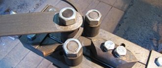
Here, as an example, I took 14 mm reinforcement, corrugated, to stretch it up to 10 mm thick and make it smooth, for future ticks.
I specially measured it before broaching, the length, as you can see, is 60 cm.
Tool required to perform drawing on an anvil: blacksmith hammer or handbrake (for more details about hammers, see the link). With a mechanical hammer, everything is, of course, much simpler.
Pulling a bar on a mechanical hammer
But we don’t have it, so we’re talking about broaching with a hammer.
In the case where the drawing is carried out by a blacksmith together with a hammer , then a hammer with a rounded wedge-shaped head is a suitable option for increasing the length of the workpiece. The process occurs in such a way that after hitting the back of the hammer with a sledgehammer, the blacksmith moves the hammer along the workpiece. The length of the workpiece increases due to the transverse depressions that are formed during the drawing process; the more there are and the stronger the blows of the sledgehammer, the longer the workpiece becomes.
Then this workpiece is leveled using a tool such as a smoother.
In cases where a very large difference is required between the cross-sectional size of the original workpiece and the required forging, a drawing with transitions is used . Let's consider the example of the need to forge a thick billet of round cross-section into a thin rod of round cross-section.
They don’t make something like this from a thick piece like this and make it so thin all at once.
Here, as in the picture, a square is made from a round cross-section, an octahedron is made from a square, and a round rod is made from an octahedron, only thinner.
Please write me a comment with your opinion about what you are watching. Please write questions and advice in the comments.
Changing the shape of the workpiece must be carried out in several approaches, which are based on drawing the metal with a subsequent change in the shape of its cross section.
To give the required shape to the workpiece, it should be turned during drawing. The turning procedure consists of rotating the workpiece by 30°, 45° and 90° around the longitudinal axis.
In order to obtain an intermediate product with an octagonal cross-section, it is necessary, after several stretches, to place the workpiece so that it lies with one edge on the anvil. After hitting the opposite edge with a hammer, you should forge along the length of the product and repeat the procedure until you get an octagonal blank . Indispensable assistants for giving the correct shape to the workpiece will be rolling and crimping tools, as well as other tools for giving a cylindrical shape.
Guy
By the way, we have a Telegram channel where we publish all the news from our Forging-Welding and Weldlek sites, as well as news from YouTube channels on the topic of forging and welding. The link is on every page of the site. Subscribe to receive news there.
Drawing is a type of drawing (drawing) , when the workpiece is pulled only at the end and a thinning is created. For example, you can sharpen a nail or a construction staple this way.
This is only one forging operation, with its help there is little that can be done, except to make a thick workpiece thinner (broaching) or sharpening a lance (draw), subscribe to the channel, because further there will be videos about how this can be applied in practice on specific simple products, and turn on the bell.
Let me show you a small guy, so I can start making a practical forged product , very simple. Hook for clothes, keys or anything else.
It will be very simple, I will do complex ones in future videos, here I want to show the simplest operations in action.
This is how we pull back the tip of a piece of rod, then we will also apply straightening and bending operations, and we will get such a simple hook. Simple, but made with your own hands and it is handmade, hand-hot forging.
Basic forging operations and the tools used.
Forging. The essence of the process.
Forging is a type of hot metal forming in which the metal is deformed using a universal tool.
Forging produces blanks for subsequent machining. These blanks are called forged forgings, or simply forgings.
Forging is the only possible way to produce heavy forgings (up to 250 tons) such as hydraulic generator shafts, turbine disks, crankshafts of ship engines, rolls of rolling mills, etc. Forgings of smaller mass (tens and hundreds of kilograms) can be produced by both forging and stamping. Although stamping has a number of advantages over forging, in one-off and small-scale production, forging is usually more economically feasible. This is explained by the fact that during forging they use a universal tool, and the manufacture of a special tool (die) with a small batch of identical forgings is not economically profitable. The initial blanks for forging heavy large forgings are ingots weighing up to 320 tons. Medium and light weight forgings are made from blooms and long products of square, round or rectangular sections.
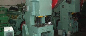
Forging equipment.
Forging is performed using forging hammers and hydraulic forging presses.
Hammers are machines with dynamic, impact action. The duration of deformation on them is thousandths of a second. The metal is deformed due to the energy accumulated by the moving (falling) parts of the hammer at the moment of their collision with the workpiece. Therefore, when choosing hammers, they are guided by the mass of their falling parts.
One of the main types of hammers for forging are steam-air hammers
. Such hammers are driven by steam or compressed air at a pressure of 0.7 - 0.9 MPa.
Forging steam-air hammers are built with a mass of falling parts of 1000 - 8000 kg. These hammers produce forgings of medium weight (20 - 350 kg), mainly from rolled blanks.
Hydraulic presses are static machines; The duration of deformation on them can range from units to tens of seconds. The metal is deformed by the application of force created by a liquid (water emulsion or mineral oil) supplied to the working cylinder of the press. Hydraulic forging presses are built with a force of 5 - 100 MN for the production of large forgings, mainly from ingots.
Technological process.
The forging drawing is drawn up on the basis of a drawing of the finished part developed by the designer, taking into account allowances, tolerances and overlaps. Allowance is a surface layer of forging metal that must be removed by cutting to obtain the required dimensions and surface quality of the finished part.
Tolerance is the permissible deviation from the nominal size of the forging indicated on its drawing, i.e., the difference between the largest and smallest limiting dimensions of the forging. Tolerance is assigned to all forging sizes.
The configuration of a forging is sometimes simplified by adding a volume of metal added to the forging over and above the allowance to simplify its shape and, therefore, the forging process. The overlaps are removed by subsequent cutting. Allowances, tolerances and allowances are assigned in strict accordance with GOST.
The choice of workpiece is carried out according to its mass, which can be calculated using the formula
where is the mass of the original workpiece; — mass of the forging, calculated as the product of the volume of the forging and the density of the metal; — mass of waste with the profitable part of the ingot; — mass of waste with the bottom part of the ingot; — mass of waste waste (scaling) when heated; — mass of technological waste.
Waste with the profitable part is 14 - 30%, and with the bottom 4 - 7%; for waste - on average 2 - 2.5% of the mass of the heated metal when heating a cold workpiece and 1.5% with each heating. Process waste (stubs, otters, etc.) depends on the shape of the forging and the forging sequence adopted. When forging from a rolled billet and are absent. The cross-sectional dimensions of the workpiece are selected taking into account the required forging. Sufficient forging for ingots is considered to be 2.5 - 3, and for rolled products 1.3 - 1.5 can be taken.
Mechanization of forging.
When forging massive forgings, our operations cannot be carried out manually at all.
To plant blanks (ingots) into the furnace and remove them from the furnace, in addition to overhead and jib cranes, special landing machines of floor-mounted or suspended types are used. Forging on presses and hammers can be mechanized using various cranes, tilters and manipulators.
The essence of the process.
Hot die forging is a type of metal forming in which the formation of a forging from a heated workpiece is carried out using a special tool - a stamp. The flow of metal is limited by the surfaces of the cavities made in individual parts of the die, so that at the final moment of stamping they form a single closed cavity (stream) according to the configuration of the forging.
Rolled round, square, rectangular and periodic profiles are used as blanks for hot stamping. In this case, the rods are cut into separate (measured) blanks, although sometimes they are stamped from the rod with subsequent separation of the forging directly on a stamping machine.
Compared to forging, stamping has a number of advantages. Hot die forging can produce forgings of complex configurations without overlaps, which is impossible with forging. Tolerances for a stamped forging are 3–4 times less than for a forged one. As a result, the amount of subsequent cutting processing is significantly reduced. Stamped forgings are processed only in places where they interface with other parts, and this processing can only be reduced to grinding.
The stamping productivity is much higher - tens and hundreds of forgings per hour.
At the same time, a stamp is an expensive tool and is only suitable for the manufacture of one specific forging. In this regard, stamping is economically feasible only when producing sufficiently large batches of identical forgings.
Hot stamping is used to produce blanks for critical parts of cars, tractors, agricultural machines, airplanes, railway cars, machine tools, etc.
Forging design.
When obtaining a forging in an open die, first of all, it is necessary to correctly select the parting surface, that is, the surface along which the upper and lower halves of the die are in contact with each other. The parting plane must be chosen such that the forging can be freely removed from the die. In order to facilitate the filling of the die cavity with metal, it is advisable to select the parting plane in such a way that the die cavities have the smallest depth.
Allowances for machining are assigned mainly to the mating surfaces of the part. The allowance depends on the overall dimensions and weight of the forging, on the type of stamping equipment, and the roughness of the machined surface of the part: allowances are selected according to GOST. Tolerances for stamping are also assigned according to GOST; Tolerances take into account possible deviations from the nominal dimensions due to understamping in height, shift of dies, their wear, etc.
To facilitate filling the die cavity and removing the forging from it, the side surfaces of the forging must have stamping slopes. Stamping slopes are assigned in excess of the allowance; they increase metal waste during machining and make the forging heavier. The slope depends on the depth and complexity of the cavity used for stamping equipment and ranges from 3 to 10º for steel forgings. For the outer surfaces of the forging (due to temperature decline), the stamping slopes are taken to be smaller than for the internal ones.
All intersecting surfaces of the forging are mated along radii.
'The internal rounding radii are 3 - 4 times larger than the external radii. The outer rounding radii r are usually 1 - 6 mm.
When stamping in dies with one parting plane, it is impossible to obtain a through hole in the forging, so only a marking of the hole is applied with a film bridge, which is subsequently removed in special dies. It is not always possible to obtain a complete forging configuration by stamping. Therefore, overlaps can be made in certain areas to simplify the shape.
By changing all the dimensions of the designed forging by the amount of shrinkage, a drawing of a hot forging is obtained, according to which the die cavity is manufactured.
When stamping in open dies, a special burr groove is made along the outer contour of the cavity. To ensure good filling of the die cavity with metal and increase its durability, the thickness of the burrs is especially important, which, like other dimensions of the burr groove, is calculated using formulas depending on the configuration of the forging.
The drawing of a forging when stamping in closed dies with one parting plane is drawn up in the same way as when stamping in open ones.
Quality control.
Quality control is necessary not only for finished forgings, but also for the conditions of their production at all stages, starting from the receipt of initial blanks. When inspecting finished forgings, they are inspected, geometric dimensions and hardness are selectively measured. Dimensions are controlled with universal measuring instruments (calipers, calipers, calipers, depth gauges, etc.) and special tools (stalks, templates and control devices). Several forgings from a batch are sometimes subjected to metallographic analysis and mechanical testing. Internal defects in forgings are determined by ultrasonic testing and x-ray scanning.
Cold extrusion.
In cold extrusion, the workpiece is placed in a cavity from which the metal is extruded into holes in the working tool. Extrusion is usually performed on crank or hydraulic presses in dies, the working parts of which are a punch and a matrix. There are direct, reverse, lateral and combined extrusion.
With direct
during extrusion (Fig. 1, a), the metal flows into the hole located in the bottom part of the matrix 2, in the direction coinciding with the direction of movement of the punch 1 relative to the matrix. This way you can obtain parts such as rods with thickenings (bolts, poppet valves, etc.). In this case, the gap between the punch and the cylindrical part of the matrix in which the original workpiece is placed must be small so that the metal does not leak into the gap.
If there is a rod at the end of the punch (Fig. 1b) that covers the die hole before extrusion begins, then the metal is extruded into the annular slot between the rod and the die hole. In this case, by direct extrusion it is possible to obtain parts such as a tube with a flange, and if the original workpiece had the shape of a thick-walled cup, then parts in the form of a glass with a flange.
In case of reverse
When extruding, the direction of metal flow is opposite to the direction of movement of the punch relative to the matrix. The most common reverse extrusion scheme is a scheme in which metal can flow into the annular gap between the punch and the matrix (Fig. 1, c). Using this scheme, hollow parts such as tubes (tube bodies), radio tube screens, etc. are manufactured.
Less commonly used is the reverse extrusion scheme, in which the metal is extruded into a hole in the punch, to obtain parts such as a rod with a flange (Fig. 1, d).
Rice. 1. Extrusion patterns
With lateral
When extruding, the metal flows into the hole in the side of the matrix in a direction that does not coincide with the direction of movement of the punch (Fig. 1, e). In this way, it is possible to obtain parts such as tees, crosses, etc. In this case, in order to ensure removal of the workpiece after stamping, the matrix is made consisting of two halves with a parting plane coinciding with the plane in which the axial lines of the workpiece and the resulting process are located.
Combined
extrusion is characterized by the simultaneous flow of metal in several directions and can be carried out using several of the previously discussed cold extrusion schemes. Figure 1, e shows a scheme of combined extrusion, combining the schemes shown in Fig. 1, a, c for manufacturing by reverse extrusion of the hollow, cup-shaped part of the part, and by direct extrusion of the rod extending from its bottom part.
The main positive feature of extrusion is the possibility of obtaining very large degrees of deformation without destroying the workpiece, which can be characterized by the indicator ( - cross-sectional area of the original workpiece; - cross-sectional area of the extruded part of the part).
For very soft, ductile metals k>100 (aluminum tubes with a wall thickness of 0.1 - 0.2 mm with a tube diameter of 20-40 mm). The possibility of obtaining such large degrees of deformation is ensured by the fact that plastic deformation during extrusion occurs under conditions of all-round uneven compression. However, the same all-round compression also leads to negative phenomena. The greater the degree of deformation, the greater the deformation force, and the specific forces acting on the punch and matrix can reach values that are several times greater than the yield strength of the deformed metal, and exceed the values permissible for the tool in terms of its strength or durability.
To reduce the specific extrusion forces when designing a stamped part, it is necessary to strive for a configuration in which there would be no stagnant zones under the end of the punch (Fig. 1, c) or at the working surface of the matrix (Fig. 1, b).
Cold landing.
Cold heading is performed using special cold heading machines. Stamped from a rod or wire. The rod is fed until it stops, the workpiece of the required length is cut off with a transverse movement of the knife and is sequentially transferred using a special mechanism to the stamping positions, where a part is obtained from the workpiece.
Cold heading machines stamp blanks with a diameter of 0.5 - 40 mm from ferrous and non-ferrous metals, as well as parts with local thickenings, solid and with holes (rivets, bolts, screws, nails, balls, rollers, nuts, sprockets, union nuts, etc.). P.). In Fig. Figure 2 shows successive stamping transitions of two characteristic parts. The name of these machines is due to the fact that the main operation performed on them is upsetting (reducing the length of a part of the workpiece with a local increase in transverse dimensions).
Rice. 2. Sequence of transitions for manufacturing parts on cold heading machines:
a – screw; b – cap;
Stamping on cold heading machines ensures sufficiently high dimensional accuracy and good surface quality, as a result of which some parts do not require subsequent cutting.
Stamping on cold heading machines is highly productive: 20 - 400 parts per minute (high productivity for smaller parts) and is characterized by a high metal utilization rate. The average metal utilization rate is 95% (only 5% of the metal goes to waste).
The essence of the method.
For sheet stamping, a sheet, strip or tape rolled into a roll is used as a workpiece for sheet stamping. The thickness of the workpiece during cold stamping is usually no more than 10 mm and only in relatively rare cases - more than 20 mm. Parts from blanks with a thickness of more than 20 mm are stamped with heating to forging temperatures (hot sheet stamping), which makes it possible to significantly reduce the deformation force compared to cold stamping. Cold sheet stamping is more widely used than hot stamping.
Sheet stamping produces a wide variety of flat and spatial parts weighing from fractions of a gram and dimensions measured in fractions of a millimeter (for example, the second hand of a watch), and parts weighing tens of kilograms and dimensions of several meters (the lining of a car, airplane, rocket).
In sheet stamping, low-carbon steel, ductile alloy steels, copper, brass containing more than 60% Cu, aluminum and its alloys, magnesium alloys, titanium, etc. are most often used. Sheet stamping produces flat and spatial parts from sheet non-metallic materials such as leather ; celluloid, organic glass, felt, textolite, getinax, etc.
Sheet stamping is widely used in various industries, especially in automobile, tractor, aircraft, rocket and instrument manufacturing, electrical industry, etc.
The advantages of sheet stamping include the ability to produce parts of minimal weight with a given strength and rigidity; sufficiently high dimensional accuracy and surface quality, allowing to reduce finishing operations by cutting to a minimum; comparative simplicity of mechanization and automation of stamping processes, ensuring high productivity (30 - 40 thousand parts per shift from one machine); good adaptability to the scale of production, in which sheet stamping can be economically feasible in both mass and small-scale production.
As a rule, during sheet stamping, only part of the workpiece undergoes plastic deformation. The operation of sheet stamping is the process of plastic deformation, which provides a characteristic change in the shape of a certain section of the workpiece. There are shape-changing
operations in which the workpiece should not be destroyed during the deformation process, and separation operations in which the plastic deformation stage necessarily ends in destruction.
Cut out the materials.
The arrangement of the contours of adjacent cut-out blanks on sheet metal is called cutting.
The type of cutting should be selected based on the condition of reducing metal waste in the die cutting (Fig. 4).
Rice. 4. Examples of cutting material with jumpers (a) and without jumpers (b): 1 – jumper.
When developing a technological process for manufacturing parts, one should strive to reduce metal losses during sheet stamping. The main waste during sheet stamping is the so-called die cutting, i.e. part of the sheet blank after it has been cut down. The shapes and dimensions of the blank being cut out are determined by the shape and dimensions of the part, as well as the form-changing operations used during the stamping process.
When stamping small and medium-sized parts, usually several flat blanks are cut out from one sheet blank for stamping. Between the adjacent contours of the cut-out workpieces, jumpers are left with a width approximately equal to the thickness of the workpiece, although in some cases adjacent workpieces are cut out without jumpers (saving metal while deteriorating the quality of the cut and reducing the durability of the tool.
Forging. The essence of the process.
Forging is a type of hot metal forming in which the metal is deformed using a universal tool.
Forging produces blanks for subsequent machining. These blanks are called forged forgings, or simply forgings.
Forging is the only possible way to produce heavy forgings (up to 250 tons) such as hydraulic generator shafts, turbine disks, crankshafts of ship engines, rolls of rolling mills, etc. Forgings of smaller mass (tens and hundreds of kilograms) can be produced by both forging and stamping. Although stamping has a number of advantages over forging, in one-off and small-scale production, forging is usually more economically feasible. This is explained by the fact that during forging they use a universal tool, and the manufacture of a special tool (die) with a small batch of identical forgings is not economically profitable. The initial blanks for forging heavy large forgings are ingots weighing up to 320 tons. Medium and light weight forgings are made from blooms and long products of square, round or rectangular sections.
Basic forging operations and the tools used.
Upsetting is the operation of reducing the height of the workpiece while increasing its cross-sectional area (Fig. 2 a). It is not recommended to deform workpieces with a height-to-diameter ratio greater than 2.5 by upsetting, since in this case longitudinal curvature of the workpiece may occur. The workpieces are settled between the strikers or backing plates.
A type of upsetting is upsetting (Fig. 2 6), in which the metal is upset only over part of the length of the workpiece.
Rice. 2. Scheme of settling (a) and disembarking (b)
Broaching is an operation of lengthening a workpiece or part of it by reducing the cross-sectional area (Fig. 3a). Broaching is carried out by successive blows with the workpiece being fed along the broaching axis and turning it 90º around this axis. Each press decreases the height of the section and increases the width and length of the workpiece. The total increase in length is equal to the sum of the length increments for each press, and the broadening along the entire length is the same.
The smaller the feed with each press, the more intense the extension. However, clamping may occur if the feed is too low.
You can pull it with flat (Fig. 3 a) and cut-out (Fig. 3 b) strikers. When broaching on flat strikers, significant tensile stresses may arise in the center of the product (especially when broaching a circular section), which lead to the formation of axial cracks. When pulling from circle to circle in cut-out dies, forces directed from four sides to the center line of the workpiece contribute to a more uniform flow of metal and eliminate the possibility of the formation of axial cracks.
Deformation during broaching can be expressed by the amount of forging:
where is the initial (large) cross-sectional area; — final (smaller) cross-sectional area after broaching.
Obviously, the greater the forging, the better the metal is forged, the higher its mechanical properties. Therefore, broaching is used not only to produce forgings with an elongated axis (shafts, levers, rods, etc.), but also in alternation with upsetting - for greater forging of the workpiece metal.
Rice. 3. Scheme of broaching and its varieties
A type of broaching is rolling on a mandrel
- an operation of simultaneous increase in the outer and inner diameters of the annular blank by reducing the thickness of its walls (Fig. 3 c). The workpiece 1 rests with its inner surface on a cylindrical mandrel 2, mounted at its ends on supports 3, and is deformed between the mandrel and the narrow long striker 4. After each press, the workpiece is rotated relative to the mandrel.
Rice. 4. Scheme of forging operations a) double-sided stitching; b) firmware
Firmware is the operation of obtaining cavities in a workpiece by displacing metal (Fig. 4 a). By using firmware you can create a through hole or recess (blind firmware). The tools for piercing are piercings (Fig. 4 b) solid and hollow; Large diameter holes (400 - 900 mm) are stitched last. Thicker forgings are stitched on both sides without a backing ring. The diameter of the piercing is chosen to be no more than 1/2 - 1/3 of the outer diameter of the workpiece. The firmware is accompanied by a retreat (otter).
Chopping is the operation of separating part of a workpiece along an open contour by introducing a deforming tool into the workpiece - an ax.
Bending is the operation of giving a workpiece a curved shape along a given contour. This operation produces squares, staples, hooks, brackets, etc. Bending is accompanied by a distortion of the original cross-sectional shape of the workpiece and a reduction in its area in the bending zone, called tightening. To compensate for the shrinkage in the bending zone, the workpiece is given increased transverse dimensions. When bending, folds may form along the internal contour and cracks along the external contour. To avoid this phenomenon, an appropriate rounding radius is selected for a given bending angle.
The listed forging operations make it difficult to produce forgings with a relatively complex configuration.
Forging equipment.
Forging is performed using forging hammers and hydraulic forging presses.
Hammers are machines with dynamic, impact action. The duration of deformation on them is thousandths of a second. The metal is deformed due to the energy accumulated by the moving (falling) parts of the hammer at the moment of their collision with the workpiece. Therefore, when choosing hammers, they are guided by the mass of their falling parts.
One of the main types of hammers for forging are steam-air hammers
. Such hammers are driven by steam or compressed air at a pressure of 0.7 - 0.9 MPa.
Forging steam-air hammers are built with a mass of falling parts of 1000 - 8000 kg. These hammers produce forgings of medium weight (20 - 350 kg), mainly from rolled blanks.
Hydraulic presses are static machines; The duration of deformation on them can range from units to tens of seconds. The metal is deformed by the application of force created by a liquid (water emulsion or mineral oil) supplied to the working cylinder of the press. Hydraulic forging presses are built with a force of 5 - 100 MN for the production of large forgings, mainly from ingots.
Technological process.
The forging drawing is drawn up on the basis of a drawing of the finished part developed by the designer, taking into account allowances, tolerances and overlaps. Allowance is a surface layer of forging metal that must be removed by cutting to obtain the required dimensions and surface quality of the finished part.
Tolerance is the permissible deviation from the nominal size of the forging indicated on its drawing, i.e., the difference between the largest and smallest limiting dimensions of the forging. Tolerance is assigned to all forging sizes.
The configuration of a forging is sometimes simplified by adding a volume of metal added to the forging over and above the allowance to simplify its shape and, therefore, the forging process. The overlaps are removed by subsequent cutting. Allowances, tolerances and allowances are assigned in strict accordance with GOST.
The choice of workpiece is carried out according to its mass, which can be calculated using the formula
where is the mass of the original workpiece; — mass of the forging, calculated as the product of the volume of the forging and the density of the metal; — mass of waste with the profitable part of the ingot; — mass of waste with the bottom part of the ingot; — mass of waste waste (scaling) when heated; — mass of technological waste.
Waste with the profitable part is 14 - 30%, and with the bottom 4 - 7%; for waste - on average 2 - 2.5% of the mass of the heated metal when heating a cold workpiece and 1.5% with each heating. Process waste (stubs, otters, etc.) depends on the shape of the forging and the forging sequence adopted. When forging from a rolled billet and are absent. The cross-sectional dimensions of the workpiece are selected taking into account the required forging. Sufficient forging for ingots is considered to be 2.5 - 3, and for rolled products 1.3 - 1.5 can be taken.
Mechanization of forging.
When forging massive forgings, our operations cannot be carried out manually at all.
To plant blanks (ingots) into the furnace and remove them from the furnace, in addition to overhead and jib cranes, special landing machines of floor-mounted or suspended types are used. Forging on presses and hammers can be mechanized using various cranes, tilters and manipulators.
Acceleration and rolling out
Video
Overclocking
The essence of the expansion operation is to increase the area of the metal workpiece by reducing the height or thickness of the cross section.
Rolling increases the diameter of a ring or pipe by thinning it by drawing out the walls.
I’ll tell you about acceleration and rolling out and show examples of how this is done.
Tool required to perform sharpening on an anvil: blacksmith hammer or handbrake (for more details about hammers, see the link above).
Well, of course, you still need an anvil and pliers . How I made anvils with my own hands and how you can quickly make pliers from old construction pliers or even from pliers, see my channel, link.
The previous forging lesson was about broaching (drawing) and guying, see the link.
You can also use rolling tools - additional tools and devices, I’ll also tell you about them now.
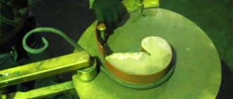
To put it in simple terms - do the acceleration - flatten it . Basically, that's all. But for those who are interested in the details, I will tell you in more detail.
In a situation where a blacksmith plans a plate from a workpiece with a large cross-section, he accelerates the workpiece in the direction from the center line to the edges . Using successive blows with a hammer, a ribbed surface with the desired width and thickness is formed. In this way, the area of the workpiece is drawn out by increasing its height . At the end of the distillation, the product is treated with smoothing irons .
I'll show you in the pictures.
The difference between rolling and broaching.
For example, straightening the ends of rods to make hooks for clothes, keys, etc. There will be a lot of videos about forging hooks on the channel, because I like to make practical things that have functional value and I think that hooks are one of the simplest products to learn to forge, subscribe so you don’t miss it, only if you this is interesting.
Acceleration using the example of a boat hook is presented in this video.
Overclocking using a shoehorn as an example is here.
Rollers (tool)
About the rolling tool (not to be confused with the rolling operation).
The essence of its use is that it enhances the flow of metal to the sides, unlike the hammer head. In theory, when rolling with the semicircular end of the hammer, we applied the principle of rolling.
Rolling can be upper or lower.
The top one might look something like this.
By the way, we have a Telegram channel where we publish all the news from our Forging-Welding and Weldlek sites, as well as news from YouTube channels on the topic of forging and welding. Subscribe to receive news there.
The lower one, or lower one, as blacksmiths say, may look something like this.
I have an old video where I experimented with rolling out, see the link.
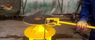
Well, here I showed with an example how you can accelerate metal using a rolling machine.
Rolling out (operation)
With the help of rolling, the diameter of the ring blank is increased by using the method of stretching the walls of the strip, the ultimate goal of which is the production of high-strength seamless rings.
This is just one forging operation, with the help of just one you can do little, except perhaps a shoehorn, subscribe to the channel, because further there will be videos about how this can be applied in practice on specific simple products, and turn on the bell .
Let me show you the acceleration on the hook, which we already saw when I had my forging lesson about the guy (if you haven’t watched it, link), I made a practical forged product, very simple.
Hook for clothes, keys or anything else. It will be very simple, I will do complex ones in future videos, here I want to show the simplest operations in action.
Now, after the tip of the hook was pulled back, the next step was to straighten it out at the opposite end of the rod, so that later a hole could be drilled on this part of the product to attach it to the wall.
This is how we first pulled back the tip of a piece of rod , then the operation of straightening (the topic of this forging lesson of mine) and bending was carried out (more on this later), and you get such a simple hook.
Simple, but made with your own hands and it is handmade, hand-hot forging.
Bending
Bending of blanks is a process in which the blanks are deformed along the intended contour.
Video
Bending of workpieces is a process in which the workpieces are deformed along the intended contour, with the outer parts of the workpiece being stretched and the inner parts being compressed. In this case, the cross-sectional area decreases by a certain value, which is called “sink”.
If you are bending flat workpieces, then the change in cross-sectional area will be imperceptible. When bending volumetric workpieces, on the contrary, a large deformation of the shapes and cross-sectional area occurs, and cracks may appear. The bending process is carried out on an anvil in a cold and hot state, using special mandrels, jigs, fixtures, machines and vices. Flat blanks made of ductile steel are bent in a cold state. There are several basic forging bending techniques, which depend on the cross-section of the workpiece.
Types of forging
The demand for forged products is extremely high, so forging technologies are being improved to this day. Products and workpieces made by forging are called “forgings”.
So, today there are three types of metal forging:
- free is a method of metal processing in which the workpiece is not limited to any shapes or is fixed to an anvil at one end. Free forging is often understood as a manual hot method of metal processing;
- machine forging of metal is carried out using special equipment - forging hammers weighing from 40 kg to 5 tons, hydraulic presses or forging machines. Using machine forging, products weighing tens of tons are produced;
- stamping is a common technology for metal deformation, in which the workpiece is placed in a mold - a stamp. Serial production items are made using the stamping method.
Now you have an idea of what metal forging is, but the review will be incomplete without mentioning the main technologies used to process steel blanks.