Preparing the product for work.
6.1.
Read the product data sheet. 6.2. Remove grease from the outer surfaces of the device and replaceable measuring rods with a clean rag soaked in gasoline and wipe dry.
6.3. The pre-indicator bore gauge must be set to the specified measured size.
The figure shows a diagram of an indicator bore gauge (design, zero adjustment diagram and measurement diagram). The sequence of setting the bore gauge to a given size using a block of gauge blocks is as follows:
a) assemble a block of gauge blocks “Dn” equal to the nominal size of the hole, or equal to the average size;
b) the block is installed in a holder (clamp) with radius sides, as shown in the figure;
c) install the bore gauge into the holder, as shown in the figure (its movable and fixed rods should be approximately located along the “0 - 0” axis, located perpendicular to the rods (initial position)
d) by unscrewing the replacement rod, set the required tension and fix it motionless with a nut;
e) tilt the inside gauge to position “1” from the initial position (or to position “2”, which is the same) and smoothly tilt it back towards position “0”. In this case, the large arrow of the indicator head moves clockwise and at a certain moment (when the bore gauge rods are positioned exactly perpendicular to the radius flanks), it will begin to move counterclockwise. By rotating the rim of the dial of the indicator head, the zero mark must be aligned with the position where the arrow changes its direction of movement to the opposite direction. This completes the adjustment of the bore gauge to the specified size.
Similarly, the bore gauge is adjusted to a given size using a setting ring or micrometer.
In the absence of a device for adjusting the bore gauge to a given size (a holder, radius flanges and a set of gauge block tiles), an adjusting ring, and also in the case when the nominal size of the hole is unknown, it is necessary to measure the holes of parts whose dimensions differ significantly from the nominal value due to their wear and tear during operation. Determine the approximate diameter of the hole (for example, using a regular ruler), select the appropriate replacement rod and install it in the body of the bore gauge (see Figure 1). Then insert the bore gauge into the hole being measured (for example, into the sleeve), and by swinging from the zero position to position “1” (or to position “2”), screwing in or out the replaceable rod, set the minimum possible tightness (size reserve) and using a nut fix the replacement rod motionless. The interference must be set as minimal as possible, since the greater the interference, the greater the error of the measurement results and vice versa. The amount of tension is controlled by the reading of the small arrow of the indicator head and this reading is remembered. Then, swinging the bore gauge to position “1” (or to position “2”), set the bore gauge to zero, as described above in paragraph “e”.
Remove the bore gauge from the hole and place it on a flat surface, or you can secure it in a vice so as not to damage or deform the bore gauge. That is, for convenience, it is advisable to position the bore gauge horizontally, motionlessly, and in such a way that the indicator dial is positioned so that it is convenient to monitor the arrow readings.
Manufacturers and best models
The recognized leaders of the market are the Japanese - the Mitutoyo brand is recognized all over the world and is rightfully considered the flagship of the field, as it offers usable and very precise (graduation value is 0.001 mm) mechanical and electronic instruments.
Mahr from Germany enjoys an impeccable reputation among European companies. Its, one might say, traditional advantage is the typical German build quality; in practice, its devices last much longer than 4-5 years, even if they are used in harsh conditions.
The best models in the CIS are representatives of the CHIZ, Microtech, Norgau, and MetroStandard series. They provide sufficient accuracy, but the price is much more affordable than the same Japanese ones.
Now you know how to use an indicator bore gauge to check cylinders, we hope you also watched the video tutorials on using a micrometer - it’s time to select and order a specific type of device. When deciding, know that you can order machines for creating precision holes (checking the compliance of which is as easy as possible) from Izhevsk.
Source
Comments 53
a micron is one thousandth of a millimeter. That is, 0.001 mm)) I have never seen such tools. And even in counters where they do boring of blocks. They work only with hundredths)))) with hundredths. Because both machines and tools measure only hundredths)) ) that is, to put it simply, if you need to bore a block of 50 mm... they will bore you 50.01
Don't worry about it! The tool is ok for a garage, I still have the Sovdep one. The main thing is to learn how to use PPC! Hundreds, microns, someone writes here - this is a common occurrence to sparkle with your mind (which, as usual, is only in theory).
All that remains is to find the manuals, which will indicate how many parrots are left before boring.
I'm afraid that without verification it's just a toy.
I won’t tell you where or what. Internet to help
Somehow, the accuracy of Chinese measuring instruments raises serious doubts
You zero on a ring or a micrometer through gauge blocks (sets 1,2,3) - and accuracy within half a hundred is guaranteed. For the square Hh7 is quite enough.
Somehow, the accuracy of Chinese measuring instruments raises serious doubts
This is a relative measurement device. You set the reference size by micrometer, and the micrometer by cmd - there will be the necessary accuracy.
Normal bore gauge and good equipment - don't listen to anyone. In the same hands it will last a long time, I more or less correctly told the people how to use it. Although the tool cannot be zeroed so abruptly when leaving the working area. I compared the work of the Swedish, American, Chinese and our domestic measurer. The domestic one is the worst in terms of performance, or rather in terms of ease of use. According to the indications, they are obviously the same - all go through a measuring laboratory when checking for accuracy.
I should have also bought a micrometer with it!
The micrometer must be taken at intervals corresponding to your cylinder diameter) usually the intervals are 0-25, 25-50, 50-75 - and 75-100. So that your cylinder diameter falls within this interval. Then you can adjust the bore gauge according to it
I work as a machine operator, I have no problems with this)))
Moreover, you are on topic)
Thank you, now I know what this is, I’ve had it lying around for about 10 years now))))) I kept wondering what this thing is for
Mechanical caliper device
How to use a micrometer correctly
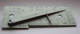
The structure of a double-sided caliper with a depth gauge is shown in the figure. The measurement range of this instrument is 0-150 mm. With its help, you can measure both external and internal dimensions, the depth of holes with an accuracy of 0.05 mm.
Essential elements
- Barbell.
- Frame.
- Sponges for external measurements.
- Sponges for internal measurements.
- Depth gauge ruler.
- Locking screw for fixing the frame.
- Vernier scale. Serves to count fractions of millimeters.
- Bar scale.
The jaws for internal measurements 4 are knife-shaped. Thanks to this, the hole size is determined on a scale without additional calculations. If the caliper jaws are stepped, as in the ShTs-2 device, then when measuring grooves and holes, their total thickness must be added to the readings obtained.
The reading value of the vernier may differ for different instrument models. So, for example, for ShTs-1 it is 0.1 mm, for ShTs-II it is 0.05 or 0.1 mm, and the accuracy of devices with a vernier reading value of 0.02 mm approaches the accuracy of micrometers. Design differences in the design of calipers can be expressed in the shape of a moving frame, measurement ranges, for example: 0–125 mm, 0–500 mm, 500–1600 mm, 800–2000 mm, etc. The accuracy of measurements depends on various factors: the reading value on the vernier, work skills, and the good condition of the instrument.
How to use a bore gauge - purpose, application and setup of the device
Parts, structural units of mechanisms and spare parts have holes and cavities, the measurement of which requires the use of specialized measuring tools. If a micrometer is designed to measure the external dimensions of various parts, then a bore gauge is used specifically to determine the internal distances between any surfaces. The device is especially popular in the mechanical engineering and instrument making industries. It is no less popular in the garage, for example, when repairing an internal combustion engine. If there is a need to obtain highly accurate data on the diameter of a hole, the width of a groove, or the distance between the surfaces of parts of complex shapes, then the material describes in detail the process of how to use a bore gauge.
How to setup?
How to use a hammer drill correctly
The bore gauge is a complex instrument that requires preliminary adjustment before use. The setting method itself depends on the main type of device. First, let's look at a simpler micrometer instrument. First of all, it needs to be reset. This requires some specific conditions. For example, the ambient temperature should be between +15 and +25°C. The ideal option is +20°C.
The head of the gauge must be placed between the measuring jaws, pressing the rod against one of them. Then you need to rotate the drum to determine the shortest distance. When the zero mark on the drum coincides with the longitudinal stroke of the rod, you can remove the head, securing the microscrew with a locking screw. Now the head is set to zero, you can unscrew the tip to select and connect the desired extension to it.
Setting up indicator bore gauges also involves zeroing. The best tool for this purpose is a calibration ring. If you don’t have it at hand, you can use a gauge gauge. To avoid significant errors when using a bore gauge, it is necessary to perform a number of actions. First, select a replacement rod and install it on the measuring rod of the tool. Then you need to set the size of this rod on a micrometer and tighten the locking screw. The rod sleeve is fixed in a vice, and its main part is placed between the measuring jaws. So, by rotating the head of the bore gauge, you need to align the arrow with the zero mark on the dial.
If all of the above steps are completed correctly, you can start taking measurements without worrying about possible errors.
Cylinder block lining process
How to tin a soldering iron tip correctly and how to use the tool?
Cylinder lining is a universal repair measure that can restore any power plant. When selecting a bushing for a cylinder block, the following requirements are met:
- for cast iron cylinder blocks, alloy cast iron liners are used;
- for blocks made of light alloys, inserts made of aluminum-based materials are used;
- for aluminum blocks, for which only expensive and scarce sleeves of original origin are suitable, it is allowed to install cast iron bushings with careful selection of thermal clearances.
With high-quality and correct lining of the aluminum cylinder block with removable cast iron bushings, an additional engine life of 130-150 thousand km can be provided.
To install the liner, the cylinders are bored with strict adherence to the correct geometry of the seat sockets. In a situation where an ellipsoidal cylinder appears, one can no longer count on normal and durable engine operation. To obtain high precision of internal surfaces, they are abrasively processed using honing tips (honing).
Hot lining of a cylinder block involves heating the block to a temperature of +140-150C, followed by installation of a liner cooled in liquid nitrogen into a thermally expanded seat. To get rid of condensation, the sleeve is pre-treated with a special agent. This method allows you to achieve a tight fit of the bushing and optimal tension over the entire area of its contact with the surfaces of the block.
The cylinder block liner can also be used using the press-fit method. This technology does not require preliminary boring of cylindrical holes. The sleeve is installed in the block using a special sealant, after which it is pressed into place.
How to Calibrate a Standard Micrometer, Set It Up, and Test It for Accuracy
Micrometers are instruments that must be checked, calibrated and adjusted before each use. We'll tell you how to do this.
First, use a thin sheet of paper to wipe the surface of your heels. To do this, bring them together by clamping the sheet with little force. Then carefully pull it out, but make sure there are no tears. As a result, the heels will be cleared of dust and grease.
Photo #16: Heel shift
Then take a reference sample and make sure that the device shows everything correctly.
Photo No. 17: checking the accuracy of readings using a sample
Otherwise, adjustments must be made.
Types of bore gauges
The following types of bore gauges are used in practice:
- lever indicator bore gauge;
- micrometric bore gauge;
- indicator bore gauge.
All of the above models are designed to perform the same technological operation - measuring hole diameters. But, they differ from each other in design and the procedure for measuring the diameter of the hole.
Micrometric bore gauges
Micrometric bore gauges (NM) are used to measure dimensions inside parts. Structurally, NMs include a micrometric head, a set of rods and a tip made of hard alloy. In addition to the above parts, the NM set includes a template (setting measure) used for calibrating the tool.
Lever indicator bore gauge
Lever indicator bore gauges are designed for taking measurements using the relative method. That is, the final result is obtained by measuring deviations from the template.
Indicator bore gauge
The indicator bore gauge includes a rod, a dial indicator, and inserts for taking measurements. These inserts have tips made of hard alloy. Some models are equipped with tips made of high-strength steel alloy that has undergone heat treatment.
ICH brand hour indicator heads are installed on the bore gauges. There may be a digital head installed. The division value on the IC is 0.01 mm; on the digital head, the division value can be 0.01 or 0.001 mm.
There are two GOSTs in force on the territory of our state - 9244 and 868. The first defines the technical requirements for indicator measuring instruments with division values of 0.001 and 0.002 mm. The second defines the technical conditions for bore gauges with a division value of 0.01 mm.
https://youtube.com/watch?v=qNnnwamK98M
These documents define the limits of measurements, errors, and tip hardness. Thus, in accordance with these documents, the indicator bore gauge NI 50 - 160 mm can have tips with a hardness of 57 units according to HRC GOST 9013. These requirements are standardized by GOST 868. The indicator bore gauge NI 100 160 can have tips with a hardness of 61 HRC. In addition, these standards stipulate that hardened steel tips are installed on measuring instruments with measurement intervals from 2 to 10 mm.
What types of bore gauges are there?
Their classification is rather arbitrary, but nevertheless, according to the method of taking measurements, they are divided into:
According to the shape of the head they can be:
By number of points of contact:
By operating range:
There is also a distinction between whether there is a vernier or not, whether the head is electronic or mechanical, and less important parameters.
How to use?
Once the device is configured, you can start taking measurements. The bore gauge is inserted into the hole to be measured.
For bore gauges with a large measuring range (more than 300 mm), the same heat-proof gaskets are supplied for the extensions.
Rotate the drum until the measuring surfaces touch the walls of the hole being measured. The tool should be slightly rocked so that it takes a position corresponding to the diameter of this hole. If you have a three-point bore gauge, you won't have to worry about this.
When the bore gauge drum is rotated to the desired position, you need to secure the screw with a stopper and remove the device. To find out the required size, add the value on the vernier scale with the length of the micrometer head and the nominal size of the extension indicated in its marking.
The micrometer view itself can also get stuck when exposed to dust and rust. Even before taking measurements, we recommend making sure that the microscrew moves smoothly and without jerking.
The measuring tip and extension must not be dirty so that the measurement error does not increase. To keep the measuring surfaces clean, it is recommended to use special safety pads. But even with full compliance with the rules for performing measurements, there are situations when you should additionally check their correctness. If you need a guarantee of accuracy, use a different (tested and calibrated!) bore gauge or micrometer.
The resulting value - the arithmetic mean of the results of all measurements - is taken as the final size. This way you can avoid random errors and at the same time average out the impact of instrument error on the measurement result.
We looked at how a bore gauge with a micrometer reading head works and how to use it. This knowledge is fundamentally important for specialist mechanics, turners, and engineers. You should also use, whenever possible, only original tools that are certified to comply with the specified technical standards.
The following video provides an overview of the micrometric bore gauge NMMTs-2.5.
How to measure with a micrometer bore gauge
The principle of working with such a device differs from measurements using indicator analogues. To measure the diameter of the cylinder, the approximate size is set on the bore gauge. After this, the micrometer head is placed in the hole perpendicular to its longitudinal axis. By rotating the drum and ratchet, it is necessary to press the measuring surfaces on both sides.
The next step is to screw in the locking screw until it stops and remove the device from the hole to take readings. To obtain the desired value, three components are added together:
- scale value;
- gauge head length;
- extension cord size, if applicable.
Measurement technology
This process is carried out in two ways: relative and absolute. The first of these requires the presence of a sample to determine the results. The second is that a device for measuring diameter is placed inside the hole and the exact distance value is determined between two points. The absolute method is measured using a micrometric bore gauge, while the relative method is performed using an indicator device.
When using a micrometric bore gauge, you first need to determine the setting measure and set the parameters to zero. To do this, the head is inserted into the hole and the drum is rotated. Then you can start taking measurements. To do this, the tip is inserted into the hole that needs to be measured. One part of it is pressed against the wall. In this case, the position of the housing must be exactly perpendicular to the axis of the hole. The handle must be turned all the way. Slightly rock the device and find the points that are farthest from each other. After this, take the readings from the device.
The indicator pen is used in approximately the same way. The difference lies in examining the results. The deviation of the arrow to the left indicates a smaller hole size compared to the standard. To the right - about larger ones by the presented number of divisions. If the cylinder size is chosen correctly, the head fits into the hole tightly, but without unnecessary effort.
Settings
Before you begin, the bore gauge must be configured. First of all, all its parameters need to be reset. For this purpose, indicator bore gauges have a gauge block, a calibration ring, and a caliper. The size of the device error is determined by measuring the standard. A rod of the required length is selected, installed in the device and secured with a key to prevent movement of the nozzle. The same value is set on the second measuring instrument and attached to the shtihmas. Then it swings in different directions. And the arrow on the dial moves away from zero. The point of maximum deviation will be considered the origin.
How to use an indicator bore gauge and important points when working with the tool
An indicator bore gauge differs from a micrometric gauge not only in design, but also in purpose. The device is not used to obtain accurate distance or diameter values, but to determine deviations from the standard readings. As in the case of a micrometer instrument, the indicator instrument should be prepared for use before use. To do this, you will need a calibration ring (template), which is necessarily supplied with the tool. A special clamp or micrometer is used to adjust the bore gauge in preparation for measuring large holes.
At this point, the setup process is considered complete, and you can proceed to the measurement procedure. We will consider below how to use an indicator bore gauge correctly.
The device is quite easy to use, so people who have mastered the operating technology do not have any difficulties using it. Below is a video that shows how to set up the device for operation by setting it to zero, and also take measurements of the part.
The indicator bore gauge is used to measure the wear level of the cylinder block, connecting rods and other parts. With its help, you can determine the possibility of further operation of the CPG, which depends on the level of wear of the cylinder walls. It is with the help of an indicator device that you can determine the level of wear and draw subsequent conclusions. You can see how to properly use a bore gauge to measure the wear level of internal combustion engine cylinders in a short video clip.
Design and principle of operation
Bore gauges are tools for finding internal dimensions (diameters of holes, grooves, etc.). They are designed for cases where the use of other tools in the form of a tape measure or ruler is not available or they are not accurate enough. The devices in question are used in car repair shops, mechanical assembly shops, and metalwork shops, for example, to measure engine cylinders.
A generally accepted classification of these devices has not been created, but bore gauges are differentiated based on various parameters. Thus, according to their design they are divided into ball, collet, etc., according to the version of the reading device - into indicator, etc., according to contact with the surface to be determined - into edge gauges, etc. The most well-known and widespread classification is based on the combination of design features of bore gauges and their purpose:
- The design of micrometric models includes a micrometric screw and drum connected by a cap, a stem with a spherical tip, a safety cap, and a stopper. In addition, they are equipped with several extension cords and a measure. The head of variants with an upper measurement value of more than 1250 mm is equipped with a clock design indicator with division intervals of 0.01 mm. The devices in question are produced on the basis of GOST 17215. There are five standard sizes of such models with different operating ranges: from 50 to 2500 mm. Options with a hour indicator are presented in three more standard sizes with a range from 1250 to 10000 mm. Devices of this type, due to their good metrological parameters (accuracy and error are about 0.01 and 0.006 mm, respectively), are usually used for accurate dimensional verification.
- Indicator bore gauges include two main units: an indicator with a clock dial and a measuring part, represented by two rods (movable, used for mounting replaceable inserts, and stationary in the housing). In addition, the body contains a system of movable levers. Indicating devices are suitable for holes with a diameter of 6 mm and have an error of 0.025-0.15 mm. The movement of the rod and the division price are 1-10 and 0.001-0.01 mm, respectively.
The first simple models of bore gauges appeared around the 17th century. These instruments were made in the form of compasses with the ends of the legs bent outward. Modern initial models, called shtichmass, are represented by tubes or rods with spherical tips. They are designed for large holes with a diameter of 100-2500 mm.
The principle of their operation is to transfer the amount of movement of the movable rod to the reading device through a transmission mechanism. Bore gauges are equipped with transmission mechanisms of various types, which also determines the scope of application. Thus, options with lever, cone and wedge gears are designed for small holes. Cone models (edge with an arrow head or a scale with a vernier, collet, ball in three sizes) are used for small holes (from 0.2, from 0.95, 3-18 mm, respectively). Most indicator bore gauges are equipped with lever or wedge type transmission devices. The working range for them is from 3 to 1000 and from 18 to 50 mm, respectively.
Another classification feature for bore gauges is the number of points of contact with the surface.
Only passimeters have three tips, one of which is movable. Such devices have a working range from 19 to 120 mm. In addition, to differentiate bore gauges, the shape of the contact surface (flat, edge, etc.) is used.
Special mention should be made of electronic models. They are represented by modifications of micrometric bore gauges equipped with an electronic head with a digital readout. As with mechanical analogues, the principle of measurement with such devices is based on comparison with a measure, which in this case is a high-precision ring.
Design and device of an indicator bore gauge
Indicator bore gauges are used to measure internal distances in a relative manner. The abbreviation NI is used to designate them, and the produced models differ from each other in the measurement range. The devices consist of an extension rod with a rod inside, a dial indicator with a scale, as well as a direct working part called a tip.
In instruments of the NI-10 and NI-18 models, a wedge gear is used as a mechanism for transmitting the force of movement of the movable rod, and in instruments of the NI-50 to NI-450 brands a lever design is used. Only on the NI-700 and NI-1000 bore gauge models, transmission mechanisms are not used, since the rod is in direct contact with the reading device.
The handle of the device is made of materials with low thermal conductivity. This is necessary to ensure that heat from your hands does not affect the measurement results. Rods are working elements that are fixed to the tip depending on the distance between the walls of the part being measured.
This is interesting! Rods are usually supplied with the device, which expands its measuring capabilities. They are made from hard steel grades, which is necessary to prevent the slightest deformation during measurements.
This is important to consider if you plan to make the rod yourself. There are no difficulties in this, since you need to select a suitable workpiece from hardened steel and cut a thread in it that matches the tip of the device.
There are two scales on the pointer indicator of the indicator pin. One scale is the main one (its division value is 0.001 mm), and it shows the relative deviation from the original position, and the second one serves to indicate the number of full revolutions of the main hand (one full revolution is equal to 1 mm).
Indicator-type devices are not designed to determine the exact dimensions of internal holes, but to identify the presence of deviations on the internal surface of the part along its entire length. The magnitude of their error ranges from 0.025 to 0.15 mm. Indicator bore gauges are classified into two types - mechanical or pointer and digital or electronic. Electronic devices are characterized by high accuracy and ease of use. Their main drawback is the price, which is 2 times higher than the cost of an analog device.
If it is necessary to obtain high-precision values, the NI-V device is used, which differs from classical models in the design of the measuring head. Its accuracy is 1 micron. Such tools are used specifically to make high-precision measurements of small holes.
This is interesting! The work of the relative bore gauge is to transmit the amount of force or degree of compression of the rod to the indicator pointer.
It is worth noting that there is no specific classification for the design of bore gauges. They are divided into two types - micrometric and indicator. Each type has its own subtypes, which differ in design and type of contact with the surface. They come in lever, cone, wedge, collet, ball, telescopic, with side jaws and others. In this material we will look at how to use a bore gauge (shtihmas) of the indicator and micrometric type, as well as what needs to be done before taking measurements, and what determines the accuracy of the results obtained.
Purpose
This tool is designed to accurately determine internal dimensions when the accuracy of a conventional caliper is not enough. A micrometer, which has the same degree of accuracy, is also widely used in production and in various workshops, but it is not always convenient for them to work.
A good example is determining the cylinder diameter in a car engine. It cannot be measured with a micrometer, and the value must be determined with great accuracy if we are talking about, say, identifying defects or diagnosing the degree of wear. It is enough for the cylinder diameter to change just a few hundredths of a millimeter during engine operation, and the piston will have play, which will soon lead to malfunction.
The method of measuring with a bore gauge with a micrometer head in such cases is quite simple. It is enough just to set the scale to zero and select a suitable extension cord from the set.
Micrometric bore gauge - how to use with photo and detailed description
Using a micrometer bore gauge is not difficult, but there are some difficulties that beginners face, which ultimately leads to incorrect readings. Let's consider the technology of working with a strokemass for measuring wide or large holes.
To be fair, it should be noted that the lower scale on the bore gauge has a division of 0.5 mm. As can be seen from the description, using a micrometric bore gauge is not at all difficult, and anyone can cope with this task if they first read the instructions. The video below shows how to use a micrometer bore gauge, the features of setting it up and reading readings.
Don't forget to take into account the instrument's error. Its value must be indicated in the passport data for each model.