Parts, structural units of mechanisms and spare parts have holes and cavities, the measurement of which requires the use of specialized measuring tools. If a micrometer is designed to measure the external dimensions of various parts, then a bore gauge is used specifically to determine the internal distances between any surfaces. The device is especially popular in the mechanical engineering and instrument making industries. It is no less popular in the garage, for example, when repairing an internal combustion engine. If there is a need to obtain highly accurate data on the diameter of a hole, the width of a groove, or the distance between the surfaces of parts of complex shapes, then the material describes in detail the process of how to use a bore gauge.
What does the device measure?
Before you buy or use any measuring device, you must first find out what you can measure with it. The main task of the bore gauge is to determine the distance from one surface to another inside the groove. The device is especially popular when it is necessary to take measurements in places where it is impossible to reach with a caliper.
Measurements of internal dimensions can be performed with a regular ruler, for which you need to attach it to the walls of the object being measured and take readings. However, such a tool is not effective when it is necessary to obtain high-precision values, which are very important in technology. Fractions of millimeters play a very important role, so a tool called a bore gauge was developed specifically for measuring the dimensions of internal cavities.
With its help, two types of measurements are performed - absolute and relative methods. To determine absolute values, a micrometric bore gauge is used. The principle of its operation is similar to a micrometer. The instrument must first be placed inside the hole, and then readings must be taken. The device allows you to obtain absolute values in millimeters.
The relative method involves the use of an indicator bore gauge (different in design from a micrometric one), which must first be moved to the working position. With its help, the size is not determined, but the deviation along the entire length of the surface is detected.
The device measures the following parameters of the part:
- diameter of holes of round, square, oval and other types of sections;
- groove width;
- distances in complex shaped parts.
The devices are simply indispensable tools for lathes and millers who turn various metal parts by hand. The device is used in workshops for repairing internal combustion engines and other mechanisms and components.
Checking bore gauges
Like all indicator instruments used in production, bore gauges must undergo periodic verification. They are carried out in laboratories certified by Rosstandart. After verification, markings are applied to the products, carrying information about the suitability/unsuitability of the instruments for carrying out measurements with the declared accuracy.
Bore gauges must be verified in accordance with the metrological testing plan approved by the enterprise, but no less than once every three years. Based on the results of inspections, protocols and acts are drawn up. Unsuitable instruments are excluded from use.
What is a bore gauge and its purpose?
Another name for a measuring instrument, which is equivalent to a caliper and a micrometer, sounds like shtihmas. Its advantage is the ability to carry out measurements with high accuracy up to 0.01 mm, and the error does not exceed 0.006 mm.
High accuracy of internal diameter measurements is needed not only in the manufacturing industry. The tool is used by jewelers engaged in the production of jewelry, shoe repair specialists, specialists in the repair of internal combustion engines, etc. Unlike a radius gauge, a bore gauge is capable of determining internal distances in hard-to-reach places (in recesses).
The device is used in the following cases:
- In the manufacture of parts with internal cavities.
- To determine the degree of wear, for example, on the walls of internal combustion engine cylinders.
- Checking the compliance of actual sizes with those declared by the manufacturer.
The bore gauge allows you to check the accuracy of various devices and certify them. Before we consider the design of the shtihmas, let’s look at the types of devices.
Device
Whatever the bore gauge, learning to use should begin with familiarization with its functional components. Therefore, we will consider designs of both types according to the method of taking measurements.
Micrometric have the following structural features:
- the screw and the drum are connected by a cap;
- the organ is a rod with a spherical tip;
- protection is provided in the form of a fuse and a stopper;
- extension cords act as additional components.
If they are capable of recording dimensions greater than 1250 mm, an hour indicator is built into their head in increments of 0.01 mm. Such models are available in 3 special versions, the range of which is 1250-10000 mm; a good addition to 5 standard options, whose scale is significantly narrower - 50-2500 mm. Metrological parameters are at their best: during operation, precision accuracy and small errors are observed - 0.01 and 0.006 mm.
The rules for using an indicator bore gauge also begin with studying its structure, which consists of the following logical nodes:
- dial showing changes in indicators;
- contact element, which is a pair of rods: the first is dynamic, allowing the installation of replaceable inserts, the second is static;
- a separate place is occupied by a complex of movable levers, which is, in fact, additional.
With tolerances of 0.025-0.15 mm, these devices are designed for holes with a diameter of over 6 mm. Their working body moves in increments of 1-10 mm with a division value of 0.001-0.01 mm, respectively, which allows you to determine the required values quickly enough.
Types of bore gauges
A bore gauge is a measuring device that is classified into two main types. The devices differ in the method of carrying out measuring manipulations. They are:
- Micrometric - designed to determine the exact distance in millimeters.
- Indicative ones differ in design from micrometric ones, and they are intended to determine the difference between the real size and the template size. Typically, such devices are indispensable tools for craftsmen involved in the repair and boring of internal combustion engines.
Internal gauges are also classified into types based on the number of points of contact. They are two-point and three-point, and differ in the number of tangent elements. The most popular among micrometer instruments are two-point models.
Three-point devices are equipped with three tips located at an angle of 120 degrees. They are used to eliminate possible subjective errors, therefore they are characterized by higher measurement accuracy in contrast to two-point measurements.
This is interesting! To obtain more accurate measurement results, necessary, for example, in the automotive industry, a pin with a pneumatic tip is used. Devices of this type are also called cork devices.
Bore gauges are classified into types according to such an important criterion as displaying the obtained values. The most popular are mechanical devices
, having a micrometric scale on which the user must independently determine the obtained values.
Indicator letter
equipped with a pointer and a measuring scale by which the obtained values are determined. The number of pointer indicators depends on the accuracy of the device.
The most expensive and accurate is the electronic bore gauge.
Instead of a measuring scale, the device is equipped with an electronic display, which displays the corresponding measurement values.
Devices are classified according to their intended purpose into the following types:
- For measuring small holes. Externally, they combine parts from a caliper and a micrometer, but their main purpose is to measure the internal holes of small parts.
- Lever - These consist of a pointer or digital display and levers connected to projecting ends. The ends are directed in the opposite direction from each other. This tool is intended for measuring the dimensions of the groove inside cylindrical parts.
There are many other modifications of bore gauges, differing in the type and shape of the tips used, with the help of which measuring manipulations are performed.
What types of bore gauges are there?
Their classification is rather arbitrary, but nevertheless, according to the method of taking measurements, they are divided into:
- Micrometric - allow you to determine the actual length using the absolute method.
- Indicative – obtain all values in a relative way, that is, by comparing them with an already configured template.
According to the shape of the head they can be:
- spherical - all surfaces are located on the same circle;
- collet - with a kind of cylinder in the final part;
- edge - with intersecting axes forming an arrow-shaped tip.
By type of transmission:
- lever;
- wedge;
- conical
By number of points of contact:
- two-pin - the most common;
- three-pin (passimeters) - with one movable tip.
By operating range:
- narrow – 18-50 mm;
- wide – 3-1000 mm.
There is also a distinction between whether there is a vernier or not, whether the head is electronic or mechanical, and less important parameters.
Design of a micrometric bore gauge
A micrometer inside gauge is designated NM, and is used to measure internal dimensions using the absolute method, that is, it allows you to find out the exact value of the distance. The components of the devices are:
- The drum is a rotating part with a vernier scale for determining readings. When the drum rotates, the rods move.
- The head is the connecting element of the drum with a removable rod and extensions.
- Locking screw or clamp - secures the device in a stationary position.
- An extension is a structural part of the device, which is used depending on the size of the part being measured.
- The tip is an important part of the measuring instrument.
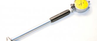
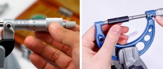
The design of a micrometric bore gauge is shown in the photo above. It is worth noting that such a tool is designed for measuring distances from 50 to 2500 mm. To determine the diameter of parts ranging in size from 5 to 50 mm, devices with side jaws are used. The design of this particular type of tool is shown in the photo below.
A bore gauge for measuring absolute values can have not only a micrometric scale for taking readings, but also an indicator one. Such devices are available in three standard sizes with a measuring range from 1250 to 10000 mm. The design of this tool is shown in the photo below.
To designate them, the abbreviation NMI is used - internal micrometric indicator meter. Measuring instruments are supplied in wooden cases, which ensure a long service life of the instruments, protecting them from the negative effects of various factors.
Design and principle of operation
Bore gauges are tools for finding internal dimensions (diameters of holes, grooves, etc.). They are designed for cases where the use of other tools in the form of a tape measure or ruler is not available or they are not accurate enough. The devices in question are used in car repair shops, mechanical assembly shops, and metalwork shops, for example, to measure engine cylinders.
A generally accepted classification of these devices has not been created, but bore gauges are differentiated based on various parameters. Thus, according to their design they are divided into ball, collet, etc., according to the version of the reading device - into indicator, etc., according to contact with the surface to be determined - into edge gauges, etc. The most well-known and widespread classification is based on the combination of design features of bore gauges and their purpose:
- The design of micrometric models includes a micrometric screw and drum connected by a cap, a stem with a spherical tip, a safety cap, and a stopper. In addition, they are equipped with several extension cords and a measure. The head of variants with an upper measurement value of more than 1250 mm is equipped with a clock design indicator with division intervals of 0.01 mm. The devices in question are produced on the basis of GOST 17215. There are five standard sizes of such models with different operating ranges: from 50 to 2500 mm. Options with a hour indicator are presented in three more standard sizes with a range from 1250 to 10000 mm. Devices of this type, due to their good metrological parameters (accuracy and error are about 0.01 and 0.006 mm, respectively), are usually used for accurate dimensional verification.
- Indicator bore gauges include two main units: an indicator with a clock dial and a measuring part, represented by two rods (movable, used for mounting replaceable inserts, and stationary in the housing). In addition, the body contains a system of movable levers. Indicating devices are suitable for holes with a diameter of 6 mm and have an error of 0.025-0.15 mm. The movement of the rod and the division price are 1-10 and 0.001-0.01 mm, respectively.
The first simple models of bore gauges appeared around the 17th century. These instruments were made in the form of compasses with the ends of the legs bent outward. Modern initial models, called shtichmass, are represented by tubes or rods with spherical tips. They are designed for large holes with a diameter of 100-2500 mm.
The principle of their operation is to transfer the amount of movement of the movable rod to the reading device through a transmission mechanism. Bore gauges are equipped with transmission mechanisms of various types, which also determines the scope of application. Thus, options with lever, cone and wedge gears are designed for small holes. Cone models (edge with an arrow head or a scale with a vernier, collet, ball in three sizes) are used for small holes (from 0.2, from 0.95, 3-18 mm, respectively). Most indicator bore gauges are equipped with lever or wedge type transmission devices. The working range for them is from 3 to 1000 and from 18 to 50 mm, respectively.
Another classification feature for bore gauges is the number of points of contact with the surface.
Only passimeters have three tips, one of which is movable. Such devices have a working range from 19 to 120 mm. In addition, to differentiate bore gauges, the shape of the contact surface (flat, edge, etc.) is used.
Special mention should be made of electronic models. They are represented by modifications of micrometric bore gauges equipped with an electronic head with a digital readout. As with mechanical analogues, the principle of measurement with such devices is based on comparison with a measure, which in this case is a high-precision ring.
Design and device of an indicator bore gauge
Indicator bore gauges are used to measure internal distances in a relative manner. The abbreviation NI is used to designate them, and the produced models differ from each other in the measurement range. The devices consist of an extension rod with a rod inside, a dial indicator with a scale, as well as a direct working part called a tip.
In instruments of the NI-10 and NI-18 models, a wedge gear is used as a mechanism for transmitting the force of movement of the movable rod, and in instruments of the NI-50 to NI-450 brands a lever design is used. Only on the NI-700 and NI-1000 bore gauge models, transmission mechanisms are not used, since the rod is in direct contact with the reading device.
The handle of the device is made of materials with low thermal conductivity. This is necessary to ensure that heat from your hands does not affect the measurement results. Rods are working elements that are fixed to the tip depending on the distance between the walls of the part being measured.
This is interesting! Rods are usually supplied with the device, which expands its measuring capabilities. They are made from hard steel grades, which is necessary to prevent the slightest deformation during measurements. This is important to consider if you plan to make the rod yourself. There are no difficulties in this, since you need to select a suitable workpiece from hardened steel and cut a thread in it that matches the tip of the device.
There are two scales on the pointer indicator of the indicator pin. One scale is the main one (its division value is 0.001 mm), and it shows the relative deviation from the original position, and the second one serves to indicate the number of full revolutions of the main hand (one full revolution is equal to 1 mm).
Indicator-type devices are not designed to determine the exact dimensions of internal holes, but to identify the presence of deviations on the internal surface of the part along its entire length. The magnitude of their error ranges from 0.025 to 0.15 mm. Indicator bore gauges are classified into two types - mechanical or pointer and digital or electronic. Electronic devices are characterized by high accuracy and ease of use. Their main drawback is the price, which is 2 times higher than the cost of an analog device.
If it is necessary to obtain high-precision values, the NI-V device is used, which differs from classical models in the design of the measuring head. Its accuracy is 1 micron. Such tools are used specifically to make high-precision measurements of small holes.
This is interesting! The work of the relative bore gauge is to transmit the amount of force or degree of compression of the rod to the indicator pointer.
It is worth noting that there is no specific classification for the design of bore gauges. They are divided into two types - micrometric and indicator. Each type has its own subtypes, which differ in design and type of contact with the surface. They come in lever, cone, wedge, collet, ball, telescopic, with side jaws and others. In this material we will look at how to use a bore gauge (shtihmas) of the indicator and micrometric type, as well as what needs to be done before taking measurements, and what determines the accuracy of the results obtained.
Bore gauge device
The indicator bore meter device requires the presence of:
- heads with a dial for determining deviation;
- measuring part.
In addition to these main parts, the shtihmas has a screw for fixing the dial, and a handle for conveniently holding the device during operation. Thanks to the presence of a centering bridge, the bore gauge is automatically aligned when it is placed in the hole.
The bore gauge dial can be digital or mechanical. In the latter variety there is a large and small scale on the surface. A large full revolution corresponds to 1 mm; using the second, the number of perfect circles is determined.
To make it possible to determine the diameter of a spare part, the design of the indicator tool assumes the presence of two types of rods, replaceable and fixed. The delivery set includes a set of heads of different lengths. When purchasing, you must pay attention to checking the functionality of all units. There should be no play after installing the movable rod.
Setting up a micrometric bore gauge - step-by-step description
To obtain accurate values measured by the bore gauge, you will need to first configure or adjust the device. The setting is carried out in the following cases:
- when the device is put into operation;
- when using it;
- after prolonged storage.
First you need to assess the condition of the device. The absence of external defects is not a reason to talk about the serviceability of the instrument. Particular attention is paid to the micrometer scale and tips. After making sure that the product is in good working order, you should proceed to the actual process of setting it up.
Initially, you should prepare the necessary materials - a screw pair (micrometer head), extension cords, a setting measure and a key. Extensions are selected depending on the nominal length indicated on the marking. The initial setting of the device to zero is checked (in other words, we find out whether it is calibrated or not). To set the micrometer bore gauge to zero, perform the following steps:
- We make sure that the ambient temperature is on average 20 degrees. Deviations upward or downward of 5 degrees or more are unacceptable, as this will affect the magnitude of the error. It is also important to take into account humidity, which should not be higher than 80%.
- We connect the screw pair with the tip.
- Next, take the setting measure and apply the device to it.
- Rotate the drum until the device is slightly fixed in the installation measure. The tightness of contact is fixed to the touch. The measuring rods should touch the work surface with little friction. The clamping screw is fixed and we check the ratio of the main scale to the vernier scale. The device is considered to be set to zero when the following picture is visible, as shown in the photo below (the mark with a zero value coincides with the mark on the main scale).
- If the value 0 does not coincide with the main risk, then the device needs adjustment. To do this, remove it from the installation measure and loosen the top nut, which is shown in the photo below with an arrow.
- Instead of a nut, there may be a hexagon screw, which depends on the tool manufacturer.
- The drum with a vernier scale rotates until it coincides with the longitudinal stroke of the stem. After the zero value of the vernier scale coincides with the longitudinal mark, you need to tighten the screw that was previously loosened.
- The actions described in paragraphs 3 and 4 with the installation measure are repeated.
You can start measuring with a micrometer bore gauge only after the device has been adjusted, that is, set to zero. This procedure is also called calibration, which must be performed before each measurement.
This is interesting! The instrument is correctly tuned when the zero stroke of the longitudinal scale is slightly visible and coincides with the zero mark of the drum. The photo shows a correctly adjusted shtihmas.
After setup, you can proceed to measuring manipulations. Let us consider in detail how to correctly measure the diameters of the internal holes of workpieces using a micrometric bore gauge.
Measurement technology
This process is carried out in two ways: relative and absolute. The first of these requires the presence of a sample to determine the results. The second is that a device for measuring diameter is placed inside the hole and the exact distance value is determined between two points. The absolute method is measured using a micrometric bore gauge, while the relative method is performed using an indicator device.
When using a micrometric bore gauge, you first need to determine the setting measure and set the parameters to zero. To do this, the head is inserted into the hole and the drum is rotated. Then you can start taking measurements. To do this, the tip is inserted into the hole that needs to be measured. One part of it is pressed against the wall. In this case, the position of the housing must be exactly perpendicular to the axis of the hole. The handle must be turned all the way. Slightly rock the device and find the points that are farthest from each other. After this, take the readings from the device.
The indicator pen is used in approximately the same way. The difference lies in examining the results. The deviation of the arrow to the left indicates a smaller hole size compared to the standard. To the right - about larger ones by the presented number of divisions. If the cylinder size is chosen correctly, the head fits into the hole tightly, but without unnecessary effort.
Settings
Before you begin, the bore gauge must be configured. First of all, all its parameters need to be reset. For this purpose, indicator bore gauges have a gauge block, a calibration ring, and a caliper. The size of the device error is determined by measuring the standard. A rod of the required length is selected, installed in the device and secured with a key to prevent movement of the nozzle. The same value is set on the second measuring instrument and attached to the shtihmas. Then it swings in different directions. And the arrow on the dial moves away from zero. The point of maximum deviation will be considered the origin.
Micrometric bore gauge - how to use with photo and detailed description
Using a micrometer bore gauge is not difficult, but there are some difficulties that beginners face, which ultimately leads to incorrect readings. Let's consider the technology of working with a strokemass for measuring wide or large holes.
- First you need to properly prepare the tool for work. This does not mean its adjustment, made in the previous paragraph, but the use of appropriate extensions, the size of which depends directly on the diameter of the part being measured. To do this, use a caliper to measure the internal diameter of the part.
- The approximate value measured with a caliper will help you select the necessary extension cord for the device. Now let's figure out how to choose the necessary extension cord. The head of the device indicates its total length, for example, 75-88 mm or 50-63 mm (depending on the model of the device). The first value indicates the length without the tip, and the second - with the tip. It is important not to confuse it with GOST, since the GOST number is also indicated on the head, for example, in the form of GOST 10-75, as shown in the photo below.
- The photo below shows what the length marking of the device looks like, which is indicated on the head of the tool.
- When the total length of the tool is known, as well as the approximate size of the hole that is to be measured with a bore gauge to obtain accurate values, it is not possible to select a suitable extension. Extensions are also marked, so if the length of the hole being measured is 104 mm, then screw a 40 mm extension to the tool (for a 50 mm device). If there is no suitable extension cord in the kit, then we assemble it from several components, for example, 25 mm and 15 mm.
- The most difficult part of the work is completed, and now all that remains is to take measurements. We place the device inside the hole and, by rotating the drum, bring the tips into contact with the inner walls of the part.
- The device should be located in the center of the part. The tips should not be pressed too tightly against the walls, but with slight (very light) force. After this, the locking screw should be secured.
- We remove the device from the part and check the quality of fixation of the removable tip. If its fastening is loose, you need to tighten it and take repeated measurements.
- After removing the device, we begin taking readings. If you used a micrometer, then there will be no difficulties in determining the readings of the bore gauge.
- If you are hearing about a micrometer for the first time, then readings are taken as follows: first, we count the total length of the device including the tip. If we use a tool with a length of 75 mm and a head of 25 mm, then we immediately get 100 mm. Next, we look at the scale and count the number of marks. What scale should you look at? Many people often get confused here, but everything is very simple. Pay attention to the location of the zero. If it is located on top, then we count the upper marks, the division of which is 1 mm.
- Based on the example in the photo, we see 4 marks, that is, 4 mm. The last line exactly matches the drum, and there are no more lines below it, so we don’t look at the bottom scale. Now we count hundredths of mm on a vernier scale. We look at the vernier mark, which coincides with the longitudinal scale. The vernier division value is 0.01 mm, so from the example we see that the value is 0.01 mm. We add up the obtained data and get: 100 + 4 + 0.01 = 104.01 mm. This is the exact hole diameter of the measured part.
This is interesting! To ensure that the measurements taken are correct, it is recommended to repeat the process, but this time measuring the distance (diameter) of the inner surface of the workpiece in a different plane.
To be fair, it should be noted that the lower scale on the bore gauge has a division of 0.5 mm. As can be seen from the description, using a micrometric bore gauge is not at all difficult, and anyone can cope with this task if they first read the instructions. The video below shows how to use a micrometer bore gauge, the features of setting it up and reading readings.
Don't forget to take into account the instrument's error. Its value must be indicated in the passport data for each model.
Purpose
This tool is designed to accurately determine internal dimensions when the accuracy of a conventional caliper is not enough. A micrometer, which has the same degree of accuracy, is also widely used in production and in various workshops, but it is not always convenient for them to work.
A good example is determining the cylinder diameter in a car engine. It cannot be measured with a micrometer, and the value must be determined with great accuracy if we are talking about, say, identifying defects or diagnosing the degree of wear. It is enough for the cylinder diameter to change just a few hundredths of a millimeter during engine operation, and the piston will have play, which will soon lead to malfunction.
The method of measuring with a bore gauge with a micrometer head in such cases is quite simple. It is enough just to set the scale to zero and select a suitable extension cord from the set.
How to use an indicator bore gauge and important points when working with the tool
An indicator bore gauge differs from a micrometric gauge not only in design, but also in purpose. The device is not used to obtain accurate distance or diameter values, but to determine deviations from the standard readings. As in the case of a micrometer instrument, the indicator instrument should be prepared for use before use. To do this, you will need a calibration ring (template), which is necessarily supplied with the tool. A special clamp or micrometer is used to adjust the bore gauge in preparation for measuring large holes.
- Work must be carried out in a temperature range from +15 to +25 degrees.
- The principle of setting is that you should initially select a replacement rod, which are supplied in the kit or purchased separately.
- The rod is fixed in the working part of the tool.
- If a micrometer or clamp is used, then it is necessary to set the size that corresponds to the rod used in the device.
- The bore gauge must be fixed in a vice through the stem bushing. However, you can instead clamp a micrometer with a preset value in a vice.
- The rod of the device is placed between the measuring jaws of a micrometer or a template clamp.
- Next, by rotating the indicator head, you need to align the arrow with the zero mark. To allow the indicator head to rotate, the locking screw must be loosened.
At this point, the setup process is considered complete, and you can proceed to the measurement procedure. We will consider below how to use an indicator bore gauge correctly.
- The tool prepared for work must be placed inside the hole with the working part. Moreover, the rod of the device must be positioned strictly perpendicular.
- Correction of the position of the instrument is carried out by lightly rocking to the sides.
- Now the most important thing is that the exact value is determined by the arrow. Moreover, it should indicate a zero value, and at the slightest displacement of the rod to the sides, it should deviate to the right or left. If the arrow points to a specific value, then the level of deviation from the norm is calculated.
The device is quite easy to use, so people who have mastered the operating technology do not have any difficulties using it. Below is a video that shows how to set up the device for operation by setting it to zero, and also take measurements of the part.
The indicator bore gauge is used to measure the wear level of the cylinder block, connecting rods and other parts. With its help, you can determine the possibility of further operation of the CPG, which depends on the level of wear of the cylinder walls. It is with the help of an indicator device that you can determine the level of wear and draw subsequent conclusions. You can see how to properly use a bore gauge to measure the wear level of internal combustion engine cylinders in a short video clip.
Maintenance and operation
In order for the device to serve its intended duration - at least 4-5 years - it must be used correctly; Moreover, it needs to be inspected regularly. The set of measures depends on the type of instrument.
Micrometric models deserve close attention - they are verified to ensure compliance with the requirements of GOST 17215-71. This interstate standard sets standards for such parameters as:
- labeling, equipment, appearance;
- drum and rod strokes;
- head radius and error;
- distance from stem to end;
- general tool tolerances, including extensions;
- rigidity (for models whose operating limit exceeds 1250 mm);
- measure parameters at contact points;
- runout in the touch zone;
- the nature of the interaction of all structural elements.
Above, we described how to properly set up a micrometer-type bore gauge, but we did not say what to avoid. For long-term and trouble-free operation, you should avoid over-tightening the extension cords. To prevent the sample from losing its reference parameters, there is no need to unscrew the screws from it or wastefully remove the rods. In the process of directly performing tasks, the tool should be held on those surfaces that do not overheat, and in places of least deflection.
It is also important to periodically inspect indicator models - verification is carried out for compliance with MI 2193-92 and 2194-92. These methods imply:
- thorough external examination;
- conducting trial tests;
- and determination of specific metrological and technical characteristics.
You should know not only how to measure a hole with a bore gauge, but also how to disassemble it. Because all components of the device must be stored separately. There is nothing complicated in this question: first you need to unscrew the rod, then separate the indicator from the rod. Each element, except the dial, must be lubricated and wiped with gasoline (preferably aviation gasoline), and then placed in a packaging box and sent to a dark place with a temperature of +15...25 degrees Celsius.
Instrument care
In order for the bore gauge to serve for a long time, it is important not to buy the most expensive foreign model, but to provide proper care for the instrument. All measuring instruments require special attention to storage and operating conditions. The bore gauge is no exception, so in order for the tool to serve for a long time, it is necessary:
- Store it in heated rooms and avoid significant temperature changes.
- When working, do not drop the tool (especially pointer models), and also eliminate the possibility of its contact with aggressive media or water.
- If the device is supplied in packaging, then this is where it must be stored.
The device may fail if used incorrectly, so it is recommended that you first study the instructions for using the tool. Having considered the design, varieties, types, as well as the features of setting up and using bore gauges, it will not be difficult to use the tools when the need arises.
Helpful tips for using and storing micrometric and bore indicator gauges
- Remember to check and adjust the bore gauges before taking measurements.
- Do not remove the adjustment screws to maintain their dimensions.
- When extending micrometer bore gauges, do not overtighten the connections.
- When taking measurements, support the bore gauges in places with minimal deflection.
- Do everything as carefully as possible. Avoid falls and impacts.
- Clean scales regularly to remove dirt.
- Store bore gauges in special cases in rooms and areas with low air humidity.
The best bore gauges in 2021
Budget
Indicative bore gauge 50-100 mm, 0.01 mm CHIZ NI 43159
This device is used to measure internal cavities and spaces between mechanisms and parts. The device is easy to use, has a handle with a special relief, which is not subject to slipping when held in the hand. This makes it possible to take measurements with high accuracy.
Indicative bore gauge 50-100 mm, 0.01 mm CHIZ NI 43159
Advantages:
- easy to operate;
- there is a special relief on the handle;
- high accuracy.
Flaws:
- not detected.
AvtoDelo indicator 40161 silver
Instrument manufacturer Avtodelo now offers instruments for internal measurements. Determination of the internal dimensions of cavities and parts located under various housings is carried out by a two-point contact, which has measuring surfaces using the relative method.
The countdown is made using an indicator with a clock mechanism. A special centering bridge allows you to align the measurement line and the axial plane of the hole that is being measured. The interchangeable rod allows you to adjust the range of desired measured sizes. It is included in the delivery package. The total range reaches 50-160 mm, the tool is supplied in a plastic case.
Cost - 4 thousand rubles.
AvtoDelo indicator 40161 silver
Advantages:
- has a clock mechanism;
- replaceable rod;
- high precision.
Flaws:
- not detected.
NI TEHRIM T050021 indicator
An indicator-type device allows you to obtain the dimensions of internal cavities and parts. The measurement is carried out thanks to a two-point contact having measuring surfaces of the relative method. The countdown is made using a clock mechanism. A special centering bridge allows you to align the measurement line and the axial plane of the hole that is being measured. The required dimensions can be adjusted using special rods provided in the delivery kit. Approved rings or gauge blocks allow this adjustment.
Cost - 4.6 thousand rubles.
NI TEHRIM T050021 indicator
Advantages:
- has a clock mechanism;
- special centering bridge;
- accuracy of measurements.
Flaws:
- not detected.
NI 6-10 0.01 Caliber
An indicator-type instrument allows you to make accurate relative measurements of internal cavities and mechanisms. Using a measuring tip, you can take measurements in hard-to-reach places where you cannot use a tape measure, micrometer, or caliper, and the data is more accurate than them.
A precision-type device allows you to determine the internal dimensions of mechanisms (the gap between two parallel planes, grooves, diameters, surfaces). Structurally, the indicator nutrometer combines hourly and digital indicators, designated CHI and QI. It is also equipped with a lever system, including movable and fixed measuring rods, and replaceable special inserts.
Cost - 4.9 thousand rubles.
NI 6-10 0.01 Caliber
Advantages:
- precise relative measurements of internal cavities and mechanisms;
- combines hour and digital indicators;
- replaceable special inserts.
Flaws:
- not detected.
Mid-price segment devices
MEGEON 80055 silver/black
This device is used when carrying out high-precision measuring work, when measuring internal mechanisms, groove diameters and other parameters. It has a measuring force from 2.5 to 5 N and a probe length of up to 6 mm. The weight of the device is small, making it comfortable to use in different conditions.
Cost - 8 thousand rubles.
MEGEON 80055 silver/black
Advantages:
- an inexperienced user will be able to understand the device;
- has a high accuracy rate;
- high measurement speed.
Flaws:
- not detected.
NI 50-100 0.01 CHIS* indicator
An indicator-type device has a purpose - measuring internal cavities and grooves of parts. If it is not possible to take measurements using a ruler, tape measure, or conventional devices, this device comes into play. There is an error (0.01 mm) when taking measurements.
To ensure accurate data, it is necessary to purchase a device manufactured directly by the manufacturer. When purchasing such a device, the warranty is confirmed by Russian standards GOST 862-82. Along with the meter, the buyer also receives documentary evidence in the form of appropriate certificates.
An indicator-type product has two components:
- Indicator head. It has a mechanical scale in the form of a circle, an arrow that moves left and right to show the desired value. With this arrow head you can easily read the measurements without requiring any special knowledge.
- Measuring rod. It consists of two working elements that have contact with the groove or boundaries of the cavity of the part being measured. The rods lead to the inner head using a mechanism that connects them.
The measurement range can be adjusted using inserts of the required sizes. Calibration is carried out using rings or gauge blocks. The tool is equipped with a handle that is protected from the effects of temperature, preventing heating. This allows you to avoid errors and inaccuracies when carrying out measuring work.
Cost - 14.5 thousand rubles.
NI 50-100 0.01 CHIS* indicator
Advantages:
- there is a comfortable handle;
- relevant certificates;
- The guarantee is confirmed by Russian standards.
Flaws:
- not detected.
NI 18-50 Range
An indicator-type apparatus is used to carry out measuring work on the internal parts of a part using the relative method. The wedge transmission and the reporting mechanism interact with each other, forming its basis. You can customize the required dimensions using certified rings and a gauge block.
Cost - 17.4 thousand rubles.
NI 18-50 Range
Advantages:
- quality tool;
- comfortable in using;
- certified instrument.
Flaws:
- not detected.
NM 100-160 Range
This micrometer-type apparatus is used to take measurements of the internal parts of a part. Measurements are made using a micrometer measuring tip head and extensions. They are the main components of the device. The head and tip contain a hard alloy. This ensures good wear resistance and a long service life.
Cost - 17.9 thousand rubles.
NM 100-160 Range
Advantages:
- hard alloy;
- good wear resistance;
- long service life.
Flaws:
- not detected.
High cost devices
MICRON electronic NI 10-18 0.001 MIC
The indicator type tool has a dial that allows you to obtain accurate results during measuring work. Used to obtain accurate data on the dimensions of the internal diameters and grooves of the part, measure the width and length.
Using a bore gauge, the depth of ledges, grooves, and various holes is measured. The error in obtaining the result is minimal. The device can be used in industry and in various industries. It is included in the State Register.
Cost - 68 thousand rubles.
MICRON electronic NI 10-18 0.001 MIC
Advantages:
- accurate results;
- the error is minimal;
- included in the State Register;
- universal in work.
Flaws:
- not detected.
How to set up a bore gauge
Setting up a bore gauge is impossible without understanding its operating principle. You should know that it is identical to the operating principle of a micrometer, which allows you to compare the indicators obtained on the two devices. If the micrometer has an error within acceptable limits, then you need to follow the following procedure to set up the bore gauge:
- Select a base rod. It can be of any length and must be mounted on a measuring rod.
- The micrometer is set to the same value as the rod.
- The locking screw must be tightened to secure the value.
- The rod sleeve should be fixed in a vice, and its main part should be placed between the measuring jaws.
- The arrow must be aligned with the zero on the dial by rotating the caliper head.
In this way, you can calibrate the value of the device and adjust it to the data necessary for operation and accurate measurement. This will make it possible to measure with an accuracy of a hundredth of a millimeter. Setting up a bore gauge is a very important process that will affect the quality of work in the future. The same algorithm is used to carry out annual verification of the device.
Measuring and reading
Set the bore gauge to approximately the size being tested and insert it into the hole. With your left hand, press the measuring surface of the tip against one of the surfaces of the part being measured, and with your right hand, rotate the drum until the micrometer screw contacts the surface of the part at the opposite point.
By rocking the bore gauge with the center of swing located at the point of contact of the tip with the surface of the part, find the shortest distance between the measured surfaces. After this, fix the microscrew with a locking screw and check the rocking force again, which should be with slight friction.
When measuring the diameter of a cylindrical hole, move the bore gauge in the transverse direction, looking for the maximum size, and then in the axial direction, looking for the minimum value.
Remove the device from the part being tested and take a reading. To do this, you need to add up the length of the micrometer head, the dimensions of the extensions used and the scale value. An example of readings is presented in the table.
| Micrometer head length, mm | Extensions used, mm | Scale readings, mm | Part size, mm |
| 75 | 50 | 8,24 | 233,24 |
| 100 |
Upon completion of work, disassemble the bore gauge in the reverse order of assembly. Wash it in clean gasoline and lubricate it with anti-corrosion lubricant for long-term storage. This also applies to installation measures and extensions.
Description and use of the bore gauge
The first devices with a similar purpose were created more than 3 centuries ago, but then they looked more like compasses. Now the usual needles have been replaced with a spherical head with rods, which greatly facilitates the penetration of the device into the smallest holes. Externally, the device looks like a tube:
The basic principle of use is that the inner rod is movable. And its movements are mechanically transmitted to a reading device. And despite the fact that the transmission system may be different depending on the variety, the basis is the same.
The main advantage of a bore gauge is that it is a device for measuring very small diameters of internal holes. It is almost impossible to perform such a task with high accuracy by other means. There are also disadvantages, but they are minor:
- the need to change nozzles depending on the size of the groove being examined;
- the need for gentle handling and careful maintenance - no sloppiness is allowed;
- you need to calibrate each time, that is, restore the system to zero.
Device information
The bore gauge is designed to measure the diameters of round parts. Its kit includes replacement rods of different calibers. They perform the function of an extension cord and a head. The last element has the following components:
- changing tip;
- locking mechanism;
- kernel;
- micrometric type bolt;
- cap;
- drum.
Area of use
The design of the device is simple and reliable. Therefore, it is used in a wide variety of industrial applications. The measurement technique is universal. Many industries require a system to take accurate readings. Bore gauges are used in the following areas:
- Mechanical engineering. This industry produces a huge number of rotating mechanisms. All parts and assemblies must have certain dimensions and precise contact with each other, with minimal gaps. Therefore, devices with minimal error are required.
- Vehicle repair. Here measurements are taken to determine the degree of wear of parts. Based on their testimony, they decide whether to repair the equipment or not.
- Metalworking industry. Here workers drill holes and mill parts. Therefore, the help of bore gauges is required.
In most cases, a bore gauge measures the diameters of the internal cavities of metal parts after turning and milling. A device is required for manual work when it is necessary to remove a thin layer from a workpiece in order to achieve high accuracy. All this is typical for the metalworking industry.
Making a workpiece with high precision dimensions is not so easy. The product must be in good condition. The qualifications of the specialist are also of great importance. Computer controlled machines are more efficient. Computer technology will allow you to achieve more accurate results.
Using a bore gauge, you can check other devices. The entire measuring instrument must be able to access the work. To do this, it must be certified.
Measurements are taken with two rounded tips located at an angle of 1800. Almost all devices have a mechanism for centering measurements. All movements of the tip are recorded on the instrument. Bore gauges allow you to take the most accurate measurements. This is their big advantage. Low cost and long service life make the tool indispensable for professionals. However, you need to remember that the internal meter requires careful handling and special care. After breakdown, the product is disposed of. Restoring the instrument is not possible. Purchasing a new device would be the best way out.
Measurements of soft parts of workpieces must be taken with caution. During the procedure, strong pressure occurs, which can deform the surface of the part.
Types of products
There are two types of bore gauges:
- devices of micrometric design;
- indicator type products.
Both types of devices need to be examined carefully. This will enable the user to choose a product with the desired parameters and characteristics.
Micrometric devices
The device has a distinctive feature. It is a micrometric screw. A special drum is firmly fixed to it. There is also a measuring tip with a stem. The design of the bore gauge resembles a micrometer. Measurements can be carried out in the range from 50 to 4000 mm.
When taking readings, the device is installed in a perpendicular position relative to the workpiece. One side of the device is securely fixed to the edge of the hole being measured. The second part moves in a diametrical position. During the procedure, the micrometer screw must be adjusted. This is necessary to obtain more accurate measurements.
The error of micrometric bore gauges is very small. Their accuracy is 0.01 mm. This is a very good indicator. The size of a circle is obtained by adding two values. The first is taken from the count of divisions on the scale. The second indicator is taken from the length of the stem and the end values. These devices are equipped with an additional adjustment measure. It is intended to check for correctness. The mechanism can also be used to adjust the accuracy of adjustment at the workplace. The micrometer device is stored exclusively in the case. It protects the product from dirt and nicks. The case will also extend its lifespan.
The instrument must be inspected at the time of purchase. Performance must be at a high level. The check is done in several steps. The instrument is first inspected visually. The buyer evaluates its configuration, labeling and manufacturer. After this, you can begin to ensure that the parts of the device interact correctly.
The bore gauge is being tested at work. It is advisable to have an instrumental microscope with you. It will help reveal the size of the stem and drum strokes. The result obtained must be compared with the factory value. Then the distance from the rod to the edge of the drum end is checked.
The next step is to examine the radius of curvature of the measuring surface of the micrometer head and tip. The measurement error is determined using a horizontal optimeter. The difference in the total size of the head and the extensions that are attached to it is calculated.
The procedure is completed by identifying the runout of the moment of contact with the measuring plane of the device and the dimensions of the installation measure at points on its working surface.
Indicating devices
Bore gauges of this type have their own design. Manufacturers installed 2 working elements on them. This includes a measuring system and an indicator head. The latter has a dial made in the form of a clock. This design is considered the most common. The tool is designed for measuring the diameter of workpieces from 6 mm and more. The error is small and can be in the range from 0.15 to 0.025 mm.
The indicator has 2 scales (one small, the other large). The first indicates the number of whole revolutions of the second dial. You need to be very careful when taking data. The second scale shows the size within 1 mm in divisions of 0.01 mm. Therefore, the measurement is calculated from the number of notches on the small dial. On a large scale, fractions of a millimeter are counted at intervals of 0.01. The movement of the rod is about 10 mm. The value can be increased if the production process requires it. For such purposes, the product comes with a set of rods of different sizes.
When purchasing, the indicator version, like the micrometric one, can be checked for serviceability. Here this procedure is made much simpler. First of all, the buyer needs to make an external inspection of the product for integrity and absence of traces of mechanical influences. Then the packaging, markings and manufacturer are checked. Some users prefer indicator types of bore gauges. Others like the micrometric option. People's opinions were divided. Everyone chooses a device to suit their needs and requirements.
The bore gauge should be checked for functionality. To do this you need to try it. The process must be completed by comparing the metrological and technical parameters of the device.
Bore gauge-plug (caliber-plug)
As can be seen from the above, all the described universal bore gauges (two-contact, technical contact) do not provide high measurement accuracy, no better than 2-5 microns. However, in automotive production, in the manufacture of fuel and hydraulic equipment and rolling bearings, higher accuracy is often required when measuring in workshop conditions.
Therefore, with the development of automatic mass production and the advent of new measurement methods, they began to produce devices with bore plug gauges. The first such devices were pneumatic devices with plugs equipped with measuring nozzles. This happened because the first measuring systems and converters that were widely used in mechanical engineering and automated production were pneumatic measuring systems of high and low pressure.
Among these systems, pneumatic instruments with plug gauges for measuring holes occupied a large place (Fig. 16).
Rice. 16 Pneumatic plug gauge
Pneumatic plug gauges have been thoroughly studied, calculated and widely used in production. GOST 14864-78 “Pneumatic plugs for holes ....” was developed.
This GOST applies to pneumatic plug gauges for manometric pneumatic systems that control holes with a diameter of up to 100 mm. GOST regulates the executive dimensions of plugs for all elements: diametric dimensions of nozzles and guides, shape and dimensions of grooves for air outlet, dimensions, diameters and shape of measuring nozzles for high-pressure bellows devices. Plugs for monitoring holes with a diameter of up to 27 mm have measuring nozzles made integral with the plug body. Larger plugs have insertable nozzles.
Later, inductive devices with inductive caliber plugs appeared, which almost completely replaced pneumatic devices due to their undoubted advantages.
Then they developed a more constructive version of the device for monitoring small-diameter holes. This device consists of a pneumatic plug gauge, a pneumatic inductive or pneumoelectronic converter, a microprocessor unit and an air preparation unit.
And finally, relatively recently they began to produce mechanical bore plug gauges.
The fundamental feature of bore plug gauges of any design and operating principle is that the plug is equipped with a guide glass, the diameter of which is very close to the size of the hole being monitored. Thus, the bore plug gauge is not a universal device, but a device designed to control the diameter of a hole of only one size. Moreover, the guide cup is made of hardened steel, chrome-plated and has the exact size and shape. The diameter of the glass is reduced by only 0.01-0.02 mm relative to the smallest diameter of the controlled hole.
The accuracy of measuring plug gauges is achieved due to the fact that, thanks to the small gap between the glass and the controlled hole, errors from distortions and displacements of the tips (Fig. 3) of the bore gauge are almost completely eliminated. Those. the tips of the device are always exactly on the controlled diameter.
The measuring range of a device with a plug gauge is small, 70-100 microns, because it is in this range that high measurement accuracy is maintained.