Here you will learn:
- What is a pressure sensor
- Purpose
- Pressure sensor device
- Kinds
- Sensor connection
- Setting the pressure switch of the pumping station
- Tips for choosing
A water pressure sensor in a water supply system is needed to automate the water supply using a pump. This sensor is mounted in close proximity to the expansion tank. Correct adjustment of the water pressure switch for the pump allows you to reduce the number of on and off cycles, thereby extending the operating life of the equipment.
What it is?
A sensor is a device that responds to changes in pressure and converts the received readings into a signal for water intake equipment.
The device is placed between the pump and the accumulator. The settings set the permissible pressure range.
The device ensures continuous operation of the home water supply:
- upon reaching the upper limit, it opens the circuit, stops water intake,
- when the pressure drops to a lower level, the pump resumes operation.
Pressure switch for water pump: connection, price, reviews
According to consumer reviews, today the relay from the Danish company Danfoss is most popular; its pressure range is 0.2-8 bar. The cost of such equipment is about 3,000 rubles. A device from the German manufacturer Grundfos with similar characteristics already costs 4,500 rubles. Italian Italtecnica equipment with standard settings will cost about 500 rubles.
Domestic devices are almost identical to Italian ones, but their cost is about 300 rubles. Thus, domestically produced products turn out to be significantly less expensive, and in terms of their characteristics they are practically not inferior to Western models.
Experts recommend installing equipment from the same manufacturer, that is, if you purchased a German pump, then the pressure switch should be from the same manufacturer.
Why is it installed?
The controller is a necessary link in the autonomous water supply system; it provides the necessary water pressure for the normal operation of plumbing fixtures and extends their service life. But with increased flow, the pressure in the system drops, and the pump operates at its limit.
A more comfortable option for controlling water supply is a combination of a sensor and a frequency converter, a device for maintaining constant pressure.
Advantages of installing an inverter:
- constant pressure in the water supply system;
- the required volume of water without limiting the pump load;
- preventing temperature surges in the heating tank due to pressure changes;
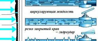
- smooth start and stop of the pump, which increases the service life of the equipment and prevents water hammer.
The pressure decreases only at a significant flow rate, when there is not enough pump power. But even in this case, the system’s performance will be stable at the level that the water intake equipment is capable of.
Design and principle of operation
Based on the principle of operation, there are controllers that control the pump by pressure or flow:
A mechanical sensor consists of a diaphragm, a system of mechanisms and levers that turn the pump on or off when the membrane deviates beyond the upper or lower limits of the set range.
Electronic, dial gauges and control units operate on the same principle; they differ in the type of signal that the device generates.- Sensors that control pumping equipment along the flow maintain approximately constant pressure with uniform water intake.
When all taps are closed, the pump pumps water to the maximum pressure point and turns off. A hydraulic accumulator is often included in the flow control unit; in this case, it has a small volume (0.2-0.6 l) to dampen water hammer without accumulation. For a flow-controlled sensor, the power of the water intake equipment is carefully calculated so as not to create excess pressure in the tank, or a reducer is installed to protect the system from extreme pressure. - When the water supply is stopped, to maintain the functionality of the water intake equipment, it is convenient to have a dry running sensor with the opposite principle of operation. The device will turn off the pump as soon as the water pressure in the system drops below the set pressure. Has a reset button or lever for forced start.
Connecting a high-frequency converter greatly improves controllability.
The inverter changes:
- the frequency of the current supplied to the pump motor,
- balances the rotation,
- pumps the volume of water that is currently consumed.
The sensor monitors system performance. The automation constantly maintains a given pressure level, which can be adjusted.
Some models
Now there is quite a large selection of pressure switches on the domestic market. Here you can find models from both Russian and foreign manufacturers. These include:
- PROMA-IDM is a universal regulator with which you can adjust the pressure of gas, air and liquid. The device body is made of plastic and is installed in a 48×96 mm hole. The converter has: four fixed ranges, improved metrological parameters, excellent interference protection, the ability to mount directly on a pipe, ambient temperature control, and so on.
- Grundfos FF is a pressure switch from German manufacturers designed for automated water supply systems at home, cottages and other facilities. The maximum setting range is from 0.5 to 8 atm, the minimum is from 0.2 to 7.5 atm. The relay can be installed in any convenient position. The device operates from a 220 V electrical network.
- SMS-PC F ¼ is an inexpensive relay regulator from a Russian manufacturer. The device is designed for operation in a pressure range from 1 to 6 bar. The electric pump starts at 1.4 bar and switches off when it reaches 2.8 bar.
- PC-58 - electronic relay is installed on the pressure water supply. The device turns off the pump in the following cases: there is no water in the system, the liquid supply stops as a result of a blockage, when water collection stops. The system can install a pump with a maximum power of 2.2 kW, the adjustment range is from 0.5 to 6 bar.
Before purchasing a device, there are several important points to consider. If you buy a relay for an autonomous system, then in this case a household device is better suited. This is due to the same indicators of key parameters of systems where the operating pressure is in the range from 1.4 to 2.8 atm. In this case, the reserve must be at least 2 atm, as this will prevent rapid wear of the membrane and extend the service life of the device.
Source
What types are there?
Controllers are distinguished by the complexity of their design and the set of commands that they are capable of sending to the system:
Mechanical sensors consist of a housing with one outlet for connection to a branch pipe.
These are the cheapest models, without pressure indication. The range is adjusted by eye, by turning the clamping nuts on the springs.- Pointers have a screen with two arrows, which show the upper and lower limits and are set with screws. They are supplied with a plug for connecting to the mains and a socket for connecting to the pump.
- Electronic differ from each other in their set of functions:
- they all control the pump, turn it on or off when the pressure leaves the specified range;
- show the current pressure value on the screen, allowing for fine tuning;
- protects against dry running with automatic multiple restarts;
- warn about leaks or ruptures of the pipeline, display an error code on the display to diagnose problems;
- in the most advanced models, a fault indication of the hydraulic accumulator has been added, which is displayed in the event of damage to the membrane or bleeding of air from the tank.
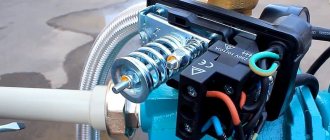
Water pressure switch for pump: connection diagram, operating principle
The relay is a block with springs that are responsible for the dimensions of the maximum and minimum values of fluid pressure. The springs are adjusted using special nuts.
The force of water pressure is directed to the membrane, and when it drops to a minimum value, the spring is weakened. When maximum pressure is reached, the membrane overcomes the resistance of the spring. This behavior of the membrane causes either the water to turn on or off. That is, as a result of the action of the membrane on the spring, the contacts located under the housing cover are closed or opened.
As soon as the liquid level reaches a minimum value, the electrical circuit closes and supplies voltage to the pump, which begins to work.
How is it different from a pressure gauge?
Pointer or electronic ones have a built-in pressure gauge, but this is only part of the sensor design. The indicating device measures and displays the pressure value on a dial or electronic display.
The sensor additionally converts the threshold values into a signal, which it sends to the pump, triggering the equipment to turn on or off.
In inexpensive models, the accuracy of readings is low . In a circuit with a sensor in the lower price segment, even if there is an indicator, a separate high-sensitivity pressure gauge is often included.
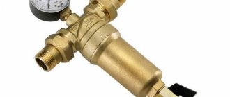
Criterias of choice
The choice depends on the purposes for which an individual water supply system is being installed. For a small country house where 1-2 people spend the season, expensive powerful equipment does not make sense.
In a family cottage, reliable and sophisticated automation with an inverter will save expensive plumbing fixtures and eliminate temperature changes while the child is bathing.
When connecting the controller to a high-frequency converter, you need to make sure that the sensor and inverter are compatible.
The price of the sensor depends on the manufacturer and set of functions. The most expensive are imported combined electronic devices that combine pump control, a dry-running sensor, and diagnostics of the entire system.
But no less popular are Russian-made devices with a price of several hundred rubles , which reliably control the autonomous system.
Where and approximately at what price are they sold?
Sensors are sold in specialized stores of plumbing equipment, electrical goods, tools, and construction hypermarkets. Prices start from 300 rubles. up to 10 thousand and above for automation with rich capabilities.
If you choose a simple model, you will additionally have to buy a dry-running sensor and a pressure gauge, so the final costs for automation may not be as low as planned.
The most advanced model for controlling a pumping station with the connection of a high-frequency converter, but the disadvantage of installing an inverter is the high price, which starts from 3,000 rubles.
Step-by-step instructions on how to connect
A detailed installation diagram for the pressure sensor is in the instructions with which the device is sold. In general, the sequence of steps is the same.
Connection to frequency converter
The sensor is connected to the inverter in the following order:
mount the sensor on the pipeline, connect the device to the high-frequency converter with a signal cable;- in accordance with the diagram given in the documentation, connect the wires to the appropriate terminals;
- configure the software part of the converter and check the operation of the connection.
To prevent interference and ensure proper operation of the inverter, a shielded signal cable is used for installation.
To the water supply system
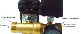
A typical sensor for installation on a pipeline requires a fitting with five terminals:
- water inlet and outlet;
- exit to expansion tank;
- under the pressure switch, usually with external thread;
- branch for pressure gauge.
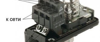
A cord from the pump is connected to the sensor to control turning it on or off. The power supply is provided by a cable that is laid to the panel.
Connection
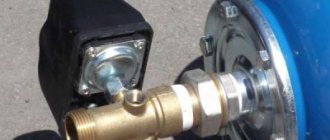
Let's look at how to connect a pressure switch (see wiring diagrams below). These blocks have a non-standard input for water connection. Household-type relays, as a rule, have a four-inch input, while professional devices can be equipped with a larger input. For this reason, it is advisable to take care of the adapter first.
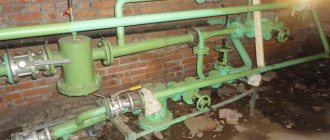
Until a certain time, in the manufacture of pumping equipment, a standard part was used, popularly called a “herringbone”. This adapter is a brass piece of pipeline measuring 100-120 mm and 25 mm in diameter. One end of it is connected to the inlet pipe of the pump. The outputs of the adapter are taps for connecting the water main, pressure switch and other equipment.
Currently, things look a little more complicated. In modern pumping units, the relay is screwed directly into the equipment, or into places that at first glance are least suitable for this.
First of all, the pump is connected to a water source, then to the power supply. Adjustment and configuration is the final, third stage of work.
How to setup?
The factory settings of the sensor are often left unchanged , but if necessary, the upper or lower limits of the range are adjusted to suit your needs. First, they test the system, record existing parameters and make adjustments.
In the water supply system
The pressure value is changed by tightening or loosening the springs:
the large one is responsible for the lower point, which turns on the pump;- set the required pressure on the pressure gauge and tighten the spring until the water intake motor starts working;
- the upper limit is changed with a small spring, then the system is tested, the actual values are checked.
In simple sensors, the housing cover is removed to access the regulators; in advanced modifications, there are external screws or buttons for adjustment.
In frequency converter
When connected via a frequency converter, changing the settings leads to a decrease or increase in the signal supplied to the converter.
A convenient mode is when the pump activation is set to approximately 1 atm. below the standard value. This difference will allow you to accumulate up to 10 liters of water in the accumulator and not turn on the pump every time you need to rinse your hands or draw a mug of water.
When it's time to take a shower, the pumping station will turn on and maintain constant pressure without a noticeable difference.
The video will show you how to adjust the pressure sensor at the pumping station:
Setting up a pressure sensor for water supply step by step
Do-it-yourself adjustment of the water pressure switch at a pumping station is accessible to users without much experience. Let's look at the setup process step by step.
Briefly, the procedure looks like shifting the adjusting nuts of two springs (spirals) - small and large. It is their relative position that creates the range we need, the start/stop points.
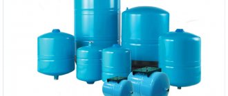
Checking the hydraulic accumulator
HA is usually purchased already inflated by the manufacturer, often at 1.5 atm. You can pump it up with a hand bicycle or car pump or compressor; Press the nipple to decrease the value. The value is measured correctly if there is no water in the container, but if the container is already installed, then you will need to empty it, drain the water and keep the nearest water tap open.
A pressure gauge is inserted into the nipple. A regular model with a width between marks of 0.1 atm is sufficient. If the indicator is excessive (as in our situation, 1.5 bar), then bleed off (press the nipple) to the required value. If the value is insufficient or there is no pressure at all, HA is pumped up. Pumping is controlled by a pressure gauge. Often compressors or modern pumps are equipped with it.
Relay and system preparation
After creating the required pressure, the tank is connected to a circuit in which a pump is already installed. Remove the cover from the relay. There should be a pressure gauge at hand.
Order:
- The system is filled with water. A number of mPa is created that is only slightly higher than the minimum. To do this, briefly start the pump, connected not through a relay, but directly. In our example, we created 1.6 atm. There is no need for special accuracy, so the indicator can fluctuate (1.7 or 1.8).
- The liquid supply is stopped and the pump is turned off. All further starts will occur through the relay.
- Use a socket or ring wrench to unscrew the nuts from the studs, and temporarily remove two adjusting springs and Belleville washers from the relay
Preparing the differential pressure switch:
- After removing the springs, nothing acts on the swinging plate, but the piston pushes it from below, since there is pressure in the system. The value is higher than the minimum, so the platform will move slightly to the upper position, and a trip will occur (disconnection of contacts), which is what we need.
- Next, you need to bring the pressure in the pump exactly to the minimum mark, to the pump activation threshold. To do this, simply open the valve of the analysis point and slowly bleed it to the required pressure gauge needle reading, in our example - 1.5 atm. After reaching the mark, the tap is immediately closed. It is convenient to have a special bleed point on the harness at arm's length; it is better to install there not a ball valve, but a valve - with it you can adjust the flow more finely.
- After setting the minimum pressure mark, the pump is powered through the relay, switching the corresponding contacts to the power supply. The RD is still open, that is, nothing will happen, it will not work, there will be no current on it. Then install a large spring, its washer, and tighten the nut.
Below is an illustration of the implementation of the second point:
Settings
Directly setting up the water pressure switch for the pump in stages:
- adjustment of the large water supply spring: the nut is turned clockwise, the spring is compressed, and the external pressure on the swinging plate increases. We need to catch the moment the release triggers to turn on the pump. Caught - the pump starts. This means that this position of the nut on the large regulator corresponds to the degree of minimum pressure for autostarting the pump;
- the pressure increases, the relay platform moves to the upper position, a shutdown occurs, but for now the deactivation mark is arbitrary, approximately 0.5 atm. above the starting point;
- the spring, washer, nut are installed in their seat;
Large spring:
Tests, features of spring interaction
Test the equipment after adjustment and correction:
- The tap is opened, the amount of mPa decreases to the minimum, to the point at which the pump starts.
- The pump turns on - the valve is closed.
- Monitor the moments of actuation on/off.
During the manipulations we have described, the desired level of relay action for opening/closing the circuit is determined and set. The following nuance is important, which helps to more quickly and accurately set the required Pmin/Pmax marks. The spring plates are interconnected and limit each other's rise/fall. An increase in the upper limit of activation (closing of contacts), also known as compression of the small spiral, affects the lower level - it increases slightly, by about 0.15–0.2 atm. Therefore, it is advisable to additionally raise the upper point by 0.2 atm, and after that, turn the nut of the large spring counterclockwise. slightly reducing the lower threshold.
After the verification and testing procedure, the threshold marks are set as accurately as possible to the specified points. In the example under consideration, the starting pressure is exactly 1.5 atm. In this case, the position of the minor spiral did not change, and accordingly, so did the difference. Let us recall that a decrease in the lower limit leads to a decrease in the upper threshold by the same 0.2 atm. The result of the adjustment is reaching the desired limit of 3 bars.
Finish stage
After adjustment, the pressure switch for the pump is covered with the cover removed before the procedure, the equipment can be fully operated. If there is a need to re-configure the installed device while using the system, then it is recommended not to limit yourself to simply tightening the nuts, but to carry out the full process as we have described.
Possible breakdowns and ways to solve them
If the pumping station malfunctions, general diagnostics are carried out to prevent pump failure or damage to the tank membrane.
Automation can cause a malfunction in the following cases:
Weak or excessive pressure occurs when the setting is incorrect; readjustment is carried out.- Loosening of the screws holding the contact group leads to spontaneous switching on or off of the device, heating and even burning of the contacts; to eliminate this, replace the unit.
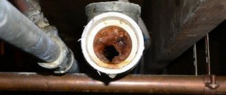
- If a pipeline or fitting is clogged, the device reacts with a delay; it is corrected by cleaning the system, and to prevent it, install reliable filters between the pump and the sensor.
Before carrying out maintenance work, turn off the power supply and do not carry out any actions while the pump is running.
The device will not work correctly if it is placed at a large distance from the accumulator or has a narrowed connection to the tank. In this case, it is easier to redo the equipment connection diagram.
The video will show you how to clean the water pressure sensor:
DIY adjustment
If for some reason the factory settings of the pumping station do not suit you, then you can connect and adjust the water pressure switch yourself. To do this you will need a screwdriver or wrench. You will also need a wrench to tighten (unscrew) the regulator nuts. Do not forget that if the component parts of the station fail, the product will lose its warranty. If the violation resulted from an incorrect connection diagram of the submersible pump, the connection as a whole was made incorrectly - all this is not a valid reason for the manufacturer.
The setup should begin by disconnecting from the voltage relay. Then the cover covering the relay is removed and adjustments are made as desired, for example, to increase pressure, measure or decrease the response range.