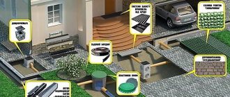
Excess water on the site, turning into puddles, is a standard problem during construction. Its solution is surface drainage systems that will cope with precipitation and melt water on your site.
Many companies supply storm and point drainage systems, and we, in turn, will tell you how to install them correctly and solve the problem on your own.
What is needed for installation?
- Level
- Tile hammer
- Cord
- Putty knife
- Shovel
- Roulette
- Bulgarian
Next, according to the drainage scheme (required on the site, you must indicate the slopes and direction of the water along the trays and select the drainage point).
Now all manufacturers leave marks on the trays indicating the direction of movement and installation. At the end of each line, a sand trap is installed, to which a drainage pipe will be connected. The sand trap is equipped with a waste collection basket, so the pipes do not become clogged.
Drainage tray device
The drainage tray is a solid U-shaped channel, the upper surface of which is covered with a grate.
According to the European classification, there are four types of trays:
- Sewage
. This design has the shape of a straight gutter that receives water along its entire length. There are two types of drainage trays: option I, which does not require a foundation or lining, and option M, which is installed on a foundation. - Box-shaped
. These devices are classic U-shaped gutters, which are equipped with removable top grilles that protect the tray channel from large objects and items. - Slotted
. Such elements of the drainage system are square beams that have an internal through channel along their entire length. The upper part has a slot through which liquid is received into the drain. These cuts can be either continuous or intermittent. Slotted trays are often analogues of box trays. - Borders
. The design of the curb trays is very similar to the previous version, with one difference: the curb trays have an L-shaped protrusion on the top edge, which hides a gap in the body. These trays are perfect not only for installation under gutters, but also near curbs. The strongest structures are used to create drainage systems for airports, highways or heavy equipment parking areas.
Design of a surface drainage system
Design is a very important stage of work related to ensuring the correct arrangement of drainage. It covers the following important aspects:
- determining the optimal type of water drainage system on the site;
- drawing up a diagram of the location of canals, water intake points and discharge points;
- identifying and purchasing the necessary materials in the right quantities.
The solution to all these problems will be impossible to achieve without taking into account a number of very important points. There are not many of them, but the final result of the work done will largely depend on them. So, special attention will need to be paid to:
- type of soil and its hardness;
- type of surface;
- groundwater level;
- layout of various buildings, structures, paths, flower beds on the site;
- frequency and intensity of precipitation.
For hard soil that allows little moisture to pass through, more channels will need to be installed. Clay soil contributes to the occurrence of waterlogging, and therefore requires the construction of underground drainage. It will be impossible to do without additional sleeves if there is a difference in the height of the area. All these factors will make adjustments to the cost estimate, but despite this, it can be argued that the design and installation of such a drainage system is very profitable.
Classification
Considering the purpose of the trays, the materials used in their production must be quite plastic, and the design of drainage trays directly depends on their properties. Today, polymers, cast iron and concrete are used to make drainage trays. These materials were chosen for a reason: concrete and cast iron are very suitable for use in foundry production lines, and plastic is perfectly processed by thermoplastic extrusion.
The result is a fairly wide range of trays made of different materials, which means that all these devices have different properties. Since the design and characteristics of the tray directly depend on the material, drainage trays are usually classified according to the type of raw material used for their production.
Storm sewer - design diagrams and types
To organize storm (rain) sewerage, two main options are used:
Open. Surface storm drainage is designed to collect precipitation from hard surfaces, which are usually asphalt or paving slabs. They are laid with a slight slope in the direction of drainage of sedimentary water.
To organize drainage, waterproof trays for transporting liquid are laid and covered with a grid. A line of trays with a slight slope is directed outside the site or brought to a drainage well.
Sometimes the slope of all drainage trays together with the site is technically unrealistic. In this case, trays of different heights are used, thus organizing a cascade drainage system without sloping the drained area towards the drainage.
Closed (underground). The underground version of sewerage is used to drain sedimentary water from buildings - residential buildings, garages, bathhouses and other structures. Water from the roofs through drainpipes enters the stormwater inlet grid, where it is physically cleaned from sand by settling. Further from the stormwater inlet, through pipes laid in the ground, precipitation is sent beyond the boundaries of the site or into a drainage well or drainage system.
Mixed. It is clear that the two considered types of organization for draining rainfall from the site serve different purposes. The open version is designed to remove sediment from hard surfaces and lawns, and the closed version is designed to remove it from the drainpipes of buildings.
Therefore, in almost all areas around individual houses, two methods of drainage are combined - above-ground and underground. It is worth noting that even if precipitation is collected from paving slabs or asphalt into gutters, it is often necessary to drain it using an underground pipeline or slope the entire surface along with a storm drain to the point of water discharge.
When using a drainage pipeline from trays, a sand trap must be installed in front of it.
Rice. 3 Scheme of storm drainage with the direction of wastewater into the underground drainage system
Related article:
Storm water inlets for storm sewers - purpose, types, design . Storm drainage involves the use of trays and storm water inlets. You can read more about wells and storm water inlets in a separate article.
Polymer
Trays made from polymers with mineral additives have very good performance characteristics.
Polymer trays are highly resistant to aggressive environments, especially chemical ones, and can withstand high loads, up to 60 tons per square meter. In addition, the material is almost impossible to damage mechanically: scratches or chips do not occur on polymer trays. Polymer products can be used at temperatures from -50 to 120 degrees Celsius. Good performance provides polymer trays with a wide range of applications: they can be used both for drainage of water near buildings and for drainage from railways. One element of the tray structure weighs about 9-14 kg.
The dimensions of a typical polymer tray vary within the following limits:
- length – 1 m;
- width – 0.14 – 0.5 m;
- height – 0.06 – 0.79 m;
- diameter – at least 0.1 m.
Marking and types of trays for heating mains
The main document regulating the dimensions of tray structures is Series 3.006.1-2.87; it also describes their marking, consisting of the following sequence of alphabetic and numeric symbols:
- L - tray, the plate that covers it is also designated similarly (letter P);
- d - placed behind the first digit indicates additional products;
- numbers from 1 to 38 indicate the serial number of the standard size and design of the product;
- The number behind the hyphen indicates the vertical pressure evenly distributed over an area of 1 square meter (m2) in kilogram-force (kgf), but more often in ton-force (tf), which the product can withstand;
- a - the letter after the second digit indicates brands with steel tabs.
There is another Series 3.006.1-8 of working drawings and standard sizes of tray elements with holes, which has a different symbol. In it, the alphabetic symbols and numbers according to their positions mean the following:
- KL - tray, PTU - overlapping corner plate, PDU - corner bottom plate, PTO - plate with a hole, LKO - tray product with a hole;
- the next three digits indicate the length, width and height of the product in centimeters;
- the last number after the hyphen is the design load in tf/m2.
Design and dimensional parameters of the tray LK 300.180.120-6 from Series 3.006.1-8
Underground structures are assembled from tray elements, which are divided into two groups:
- channels - products with a net height of less than 150 cm;
- tunnels - engineering communications from trays with a height of 180 cm or more.
The marking of channels and tunnels has an alphanumeric designation, similar to trays, and consists of the following symbols:
- KL - tray channels covered with slabs;
- KLP - channels of trays that rest on slabs;
- KLS - Structures made of two reinforced concrete products resting on the ends of each other’s side walls.
The number after the letter designation indicates the width of the channel in centimeters, the next number indicates the height of the tray in centimeters. The digital symbol after the hyphen is the workload in tf/m2.
Characteristics of trays of extreme standard sizes according to Series 3.006.1-2.87
Concrete
The materials for the manufacture of concrete trays are various mixtures reinforced with fiberglass, polymer concrete and steel wire.
The production method is vibration casting, in which a cast but not frozen form is immersed on a specially equipped stand. Concrete trays are very durable, especially in comparison with typical reinforced concrete structures. Concrete trays are used in different ways: they can be used to make both a home drainage system and drainage for roads.
Dimensions of concrete trays:
- length – 0.5 – 4 m;
- width – 0.14 – 0.43 m;
- height – 0.15 – 0.88 m;
- the diameter may vary, but cannot be less than DN 100.
The exact dimensions of trays are determined for specific cases or according to industry standards.
Stages of surface drainage assembly
- The initial stage of installing the system involves digging a trench. Its width should be twice as wide as the drainage tray. To correctly calculate the dimensions of the trench, the height of the concrete base, the width of the side supports, as well as the thickness of the grating, which should be located 3-7 cm below the surface of the site, must be taken into account.
- It is important to make sure that the soil can withstand the planned level of load.
- If the installed drainage system includes sand traps, then trenches will need to be prepared for them. Installation of sand traps is allowed when the drainage system is connected to an underground sewer system.
- Following the preparation of the trench, the stage of filling it with a concrete base of grade M 50-M75 follows. The sides of the trench are also strengthened using concreting. The thickness of the layer of slopes and side channels should not be less than 10 centimeters. If vehicle traffic is not planned on the pavement being constructed, concrete can be replaced with sand and crushed stone. This will not affect the quality.
- A sand trap should now be installed in the appropriately prepared trench.
- After installing the sand catcher, you will have to start assembling the drainage system and installing it in the trench. The channels are attached end-to-end using a groove and tongue located at opposite ends, which eliminates the need for additional sealing. The fastening process should begin from the outlet hole.
- Arrows must be used to mark the movement of water on the vessels for collecting water. This factor will then be taken into account when laying the catch basin.
- If there is a need to fasten the channels at an angle, they should be cut manually using a saw equipped with a diamond blade.
- A system for surface drainage of excess water and sewerage is connected via a sand trap using a D100 pipe. To do this, you need to pull the plug out of the outlet body in advance. If the connection of the drainage system to the sewer system is carried out without the use of a sand trap, but with the help of vertical pipes, then you will need to remove the hole located at the bottom of the channels from the plug. This is done simply - carefully drill along the contour and knock out the plug with a light blow, and insert the pipe into the resulting hole.
- Fill the remaining free space in the trench with earth and crushed stone and compact it well.
- Cover the trays with gratings so that the top layer of soil is located 3-6 cm above the drainage systems.
- Point storm water inlets are connected to the sewer system in the same way using a PVC D100 pipe, without affecting the sand trap.
- The surface water supply system requires periodic cleaning of the system. It should be carried out 2-3 times within a month, while emptying the grates and filter from the sand trap.
Cast iron
In the production of cast iron trays, two grades of cast iron are used:
- cast iron with lamellar graphite grain;
- cast iron with spherical graphite grain.
This material is part of the product profile and its lattice. Considering the fact that cast iron is very susceptible to corrosion, finished structures are galvanized, but usually this procedure is performed optionally: the client can order a tray without a zinc coating.
Since cast iron has good resistance to longitudinal and transverse loads, products made from it are used in places where they will be subject to great forces.
Typically, cast iron trays are installed on runways, truck stops and other areas: the use of cast iron trays on private land is not justified from a financial point of view. Dimensions of typical cast iron products:
- length – no more than 0.5 m;
- width – no more than 0.2 m;
- lattice thickness – from 0.05 m;
- internal diameter – from DN 100.
Basic functions of point drainage
It is appropriate to install point drainage systems if there are problems associated with strong flows of water during rainstorms or floods, since their main purpose is local water collection. This type of water collection will be a very good addition to a linear moisture drainage system.
The design of this system itself is a set of water intakes located in the most problematic areas of the site. These places are determined by observing those points of accumulation of water where it accumulates and lingers the most.
When installing point drainage, you can use stormwater inlets such as wells or curbs, as well as plastic stormwater inlets. The end walls of the vessels provide special connections with pipes having a diameter of 50-160 mm.
The best results in the fight against precipitation can be achieved through the rational use of the two systems described above simultaneously.
Recommendations for choosing materials for installing surface drainage
The correct selection of materials for installing drainage depends on factors such as the type of existing coating, the topography of the site, and climatic conditions. Taking into account all these nuances, at the time of starting work it is recommended to have in stock:
- a shovel for digging a trench;
- concrete for filling the trench;
- storm water inlets, trays, gutters;
- grids for collecting large technical impurities;
- sand receiver for water filtration.
All of the above materials must be of very high quality, since the reliability of surface drainage and its durability will then depend on them.
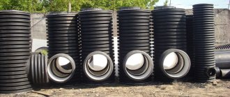
Types of trays and storm water inlets for the drainage system
Trays and storm water inlets are the main elements of drainage. They are divided into shooting categories - concrete, plastic and polymer concrete. The choice of material in each specific case will depend on the purpose of the area where they are supposed to be constructed.
- Concrete trays They are usually protected by gratings made of cast iron or steel and equipped with special fasteners, thanks to which the reliability of the system as a whole increases. Among the main advantages of these trays are high strength, moisture resistance and self-cleaning. Concrete gutters are not very expensive and can easily withstand loads of up to 90 tons.
- Plastic trays are easy to install, have increased throughput, are durable, and weigh relatively little. Considering the fact that the maximum load for plastic trays is 25 tons, their use in areas with increased load is not recommended. This advice does not apply to F class trays with steel nozzles and a cast iron grate. Concrete and plastic storm water inlets can be used successfully even on a small budget. Plastic trays are installed in pedestrian areas, while concrete trays should be preferred for higher loads, for example, where there is vehicular traffic.
- Polymer concrete trays are a kind of synthesis of concrete and plastic storm water inlets, as they combine all their best qualities. They are durable, moisture-resistant, resistant to dynamic influences, and have excellent throughput. They really cost more, but they pay for themselves quickly enough, since they perfectly retain all their technical advantages even after the expiration date stated by the manufacturer.
Grids for drainage storm water inlets can be of the following types: steel, cast iron, galvanized, polymer, metal, plastic and stamped. They all have their advantages, but cast iron grates are the most practical. Their service life reaches 30 years. For metal gratings it is a maximum of 10 years, and for polymer gratings only 5 years.
Load class of trays and rainwater inlets
When choosing trays and storm water inlets, which are important components of surface drainage, it is imperative to take into account their load class, which depends on the location of application and the required throughput.
- When arranging squares, park areas, pedestrian areas, products with special markings are used - A 1.5 t.
- When installing drainage on roads with low and medium traffic volumes, you should purchase products marked B 12.5 t or C 25 t.
- For draining the surface of such large objects as factories, loading terminals, airports or gas stations for vehicles, the most suitable products are class D 40 t or E 60 t.
- In the case of private construction in pedestrian areas, you should pay attention to class A 15 gratings. For parking areas, class B 125 products are best suited.
Rules for installing drainage trays
Installation of drainage trays requires special attention, so this operation must be handled extremely responsibly.
Since surface drainage is installed in rather complex soil, one cannot hope for serious support. Soil freezing also needs to be taken into account: the vast majority of soils freeze to at least 1-1.2 m in winter, which has an extremely negative effect on the trays, literally squeezing them out of the ground. The following rules will help you take into account most of the factors influencing the drainage system:
- When designing a rainwater collection system, it is necessary to choose the right drainage trays. Having calculated the amount of precipitation for a certain period, it is necessary to increase this figure by 25%, and select drainage trays based on the result obtained.
- The purpose of the product must also be taken into account, on which the material and dimensions of the trays will depend. For example, using powerful cast-iron trays on your home site is completely unprofitable, and more fragile structures are not suitable for parking lots or airfields.
- The laying of drainage trays must be done correctly, and one of the prerequisites is that the system slope must be maintained - at least 10 mm per meter of length.
- It is not advisable to install trays directly on the ground: it is worth making at least a small lining layer of sand and gravel. The ideal option would be a 10-centimeter layer of crushed stone, and the structure laid on it will last much longer.
- Installation of drainage trays made of steel is easier because their weight is less than their cast iron counterparts. In addition, the service life of steel trays is longer.
- The drainage system should be equipped with sand traps to prevent siltation of the structure.
- The grille must be fixed firmly so that it does not move. For these purposes, the trays are equipped with mechanisms equipped with a screw lock.
These tips will improve the quality of storm drainage and increase the service life of the storm drain.
III. GUIDELINES FOR LABOR ORGANIZATION
Excavation work to excavate pits for sockets and trenches for tray blocks must be completed before installation work.
The blocks must be delivered to the work site in advance. At the exit bell pit, the outlet bell blocks and several tray blocks are unloaded (depending on the size of the boom of the truck crane). The remaining tray blocks are unloaded along the trench near the truck crane parking areas, and the upper bell blocks are unloaded at the pit of the upper bell. The blocks must be folded so that they do not interfere with the passage of the truck crane.
Crushed stone for crushed stone preparation is unloaded at both sockets and intermediate stops.
Excavation work to construct a trench for the tray is carried out by a team of workers consisting of: an excavator operator of 6 grades, and excavators: 3 grades. — 1, 2 sizes - 2.
Excavators carry out work on the rough leveling of the trench and pits after the work of the excavator, digging trenches under thrust spurs and under stops, and then finally planning the bottom of the trench under the lath, giving a slope.
The installation of the blocks is carried out by a team consisting of: truck crane operator 5 r. and erectors of structures: 4 grades. — 1, 3 sizes - 2.
In the process of performing work, the installer of 4-grade structures. gives instructions to the truck crane operator to lift and lower the blocks, monitors their correct installation.
Installers of structures 3 grades. they sling the blocks and direct them to the laying site, and also arrange crushed stone preparation.
To excavate trenches and pits, fill the cavities with soil with compaction and final leveling of the surface near the tray, the following are involved: an excavator operator of 6 grades, a compressor operator of 4 grades. and digger 3 sizes.
Linear drainage from trays
The installation of drainage trays looks like this:
- The first step is to outline the proposed axis along which the storm drainage system will pass. You don’t need any special equipment for this; just use stakes and twine.
- After this, the internal diameter of the tray is calculated, for which it is necessary to find out the average precipitation in the selected region.
- Having determined the diameter, you can begin to select the trays themselves and their sizes.
- To install trays, a trench is required, and its dimensions should be larger than the dimensions of the trays, by approximately 30-40 cm. The depth of the trench can be lowered by 10-15 cm.
- The excavated trench must be properly reinforced so that the soil does not begin to move after the trenches are installed. The bedding should hold the ground and at the same time provide a slope to the structure.
- Next, trays and sand traps are installed in the prepared ditch. The last catcher in the chain must be connected to the site's drainage system.
- To firmly fix the position of the drainage system, the space between the walls of the trays and the ground is filled with concrete.
Conclusion
Installation of drainage trays is required in many areas, especially in regions where precipitation levels are above average.
The created design will allow all surface water to be drained into the water intake, and the area will be protected from excess moisture. If necessary, you can install drainage trays with your own hands; the created design is in no way inferior to the work of specialists.
Installation of water drainage trays
Tool
It is quite possible to do the installation of drainage trays yourself. To do this you will need desire, technical savvy and a set of tools.
The most common tool needed:
- shovel,
- Bulgarian,
- level,
- thread,
- marker,
- rubber hammer,
- Master OK,
- basin for solution,
- construction knife,
- chisel,
- an ordinary hammer.
In addition, the technology requires the presence of a drawing or diagram according to which the trays will be installed. If you don’t have a professional document, draw the installation diagram “by hand” so that you don’t confuse anything during the work.
Step-by-step installation
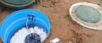
The drainage system includes trays and a sand trap. The latter is installed at the lowest point. From it water flows into.
There is a special basket inside the sand catcher where settling debris and sand accumulate. Don't forget to clean it!
Instructions for installing concrete trays:
Do-it-yourself storm drainage - installation features
It is worth noting that installing a storm drain in a private house is within the capabilities of any owner who has the appropriate knowledge and basic experience in construction work. The main difficulty lies in drawing up drainage plans and drawings and carrying out the necessary calculations.
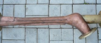
Self-manufacturing of gutters
Theoretically, storm drainage can be made in a private house with your own hands without using commercial trays. To do this, dig a trench in the ground with or without a slope, lay formwork from boards and fill it with concrete or cement-sand mortar, being careful not to fill the middle.
Then a piece of smooth-walled PVC-U pipe with a diameter of 110, 125 or 160 mm (its walls are pre-lubricated with used machine oil) is pressed halfway into the fill, preferably 6 m long, at the desired angle (average slope 7 mm per linear meter), the excess solution is removed. The pipe is left until the solution dries completely for 1 - 2 days.
Since the surface of the resulting gutter will not always be smooth due to the lack of vibrations, after filling it you will have to seal the cracks and cavities. You can do it in a more efficient way by cutting the forming pipe lengthwise and leaving half of it in the tray forever.
A home-made gutter obtained by this method has a number of advantages over a purchased one, related primarily to financial savings and the high quality of a single line of stormwater system without butt joints.
If necessary, it is easy to make trays yourself in a similar way. To do this, make a rectangular shape from boards, lay an inverted PVC pipe cut lengthwise, greased with oil on the bottom and fill it with concrete. To compact the concrete mixture, they use artisanal vibration - they place the form on the tire and hit the rubber through the board with a hammer drill in the bumper mode.
Rice. 16 Examples of self-made gutters
Installation of storm drainage from ready-made trays - recommendations
Linear (trough) storm drainage in a country house or cottage is designed to provide water collection and drainage from the hard surface of large areas; sometimes it is also used for lawns.
When arranging a tray sewer system, it is useful to be guided by the following considerations:
- When carrying out excavation work, make a slope of the site with a hard surface (paving slabs) towards the flume channel of about 0.5% or 5 mm per linear meter. The slope may be less if a smooth asphalt or concrete waterproof covering is laid.
- If the drainage occurs from the blind area around the building into a linear sewer, its slope is much greater, for example, at least 2.5%, similar to the road surface (25 mm per linear meter).
- To direct stormwater to the drainage structure, the trays will have to be sloped. In concrete structures, the manufacturer lays a slope directly in the trays themselves at 0.5 or 1%, forming them into a continuous line of different heights. The user can only connect these gutters into a single highway.
Rice. 17 Scheme of laying linear sewerage
- Polymer trays are made without a slope, so when constructing a sewer using them, you will have to tilt the entire site along with them by 0.5 - 1%. The second way out of the situation is to use a cascade connection of trays of different heights, which are produced by almost every commercial company that manufactures them.
- When installing a tray sewer, the following operations are carried out:
- Dig a trench, the overall dimensions of which depend on the size of the trays and the thickness of the concrete base at the bottom and sides. Sand is poured into the bottom of the trench in a layer of about 30 mm to level it, then the sand cushion is compacted.
- Place a layer of concrete 50 - 100 mm thick (depending on the load class) at the bottom of the ditch, lay trays on top and level them to the level of the site. Polymer products are connected into locks, the joints are coated with sealant.
- The straightness of the laying of the trough line is checked with a pre-tensioned cord; individual gutters are checked with a metal level; if adjustments are necessary, they are tapped with a rubber mallet.
Rice. 18 Tray storm sewer - installation stages
- When laying, make sure that the height of the linear tray drainage with the lid on is 3 - 5 mm below the level of the site covering.
- Also, the side walls of the trays are covered with concrete or a cement-sand mixture, leaving space for laying paving slabs. To prevent the ditch from crumbling, to have the same filling thickness on the sides, and in order to save material, boards of the appropriate width are laid on the side walls of the trench, thus forming a kind of formwork.
- If further pipe drainage is necessary, a sand trap is installed at the end of the flume line and a pipeline is connected to it.
- After the concrete or cement-sand mixture has hardened, the trays are covered with lids and paving slabs are added. A damper tape is placed in the narrow space between the street covering and the trays to compensate for linear deformations.
Rice. 19 Storm sewer - laying diagram and main components
What materials are used for waterproofing?
Waterproofing of heating main trays, the technology of which, depending on the purpose, location and operating conditions, is made from the following materials:
- bitumen, polymer or composite roll or sheet textures are used for adhesive waterproofing;
- coating waterproofing is carried out by applying mastic in several thick layers;
- plastering is done using coating materials of lower mobility, made on the basis of pneumatic concrete, polymer concrete, gunning mortar, asphalt mortar and mastic, etc.;
- painting waterproofing is applied to the outer part of trays of paste and liquid foaming materials;
- clay waterproofing by applying rich clay to the joints of the structure. The layer clogs the concrete trays, making it almost impenetrable;
- Rigid sheet waterproofing consists of rigid installation of polymer sheets to trays and floor slabs using anchors, screws, dowels, glue or welding.
Regardless of the type and materials of waterproofing, it is necessary to thoroughly prepare the treated surfaces and the environment from excess moisture and debris.
Tray waterproofing technology
It is necessary to reduce the water level in the canal before installing waterproofing using drainage or drainage drains. If work is carried out in slumping soil or a deep pit, it will be necessary to install sheet piling barriers.
To protect the open pit from flooding by storm water, it is necessary to install ditches with wells to collect water around the concrete trays.
Then the insulated surfaces are prepared and subsequently processed:
- smooth out uneven areas and seal joints with plaster mortar;
- clean the surface from dust and debris;
- If you are treating with hot mastics, dry the surface. And moisten when processing with plaster.
With proper processing and installation of structures, technology for laying heating main trays in compliance with building codes and operating conditions, heating main trays will last the required time, creating comfortable conditions for communications.