When equipping an individual hydraulic extraction point on a site (for example, a well or well), it is also necessary to install a hydraulic accumulator. This is a storage tank with a complex device, an integral part of which is a small device used to measure the liquid level in the storage tank. In the article we will talk about the water pressure switch for a submersible water pump (pumping station) in the water supply system, we will talk about adjusting and configuring the sensor according to the instructions.
Technical device
To understand how this part works, you need to consider the entire structure of the water supply as a whole. The liquid enters the hydraulic accumulator. This is a container that is divided into two parts by a membrane partition. One contains compressed air, the other contains liquid. In this way, the volume can be adjusted; as a rule, no more than 40% -50% of the total capacity of the tank is pumped.
Household appliances that are included in the home water supply system can usually operate within the range of 1.4 to 2.8 atmospheres. To maintain this range, so that there are no breakdowns of water heaters, dishwashers and other electrical assistants in the home, a sensor is needed. But there are no strict standards for this indicator; the user can independently adjust the water pressure switch and adjust his own values.
The mechanism has two limits - these are the upper and lower limits, respectively, when the atmosphere becomes more and less than required, the device is triggered. When new fluid does not arrive, the old fluid is consumed from the storage tank. And when its level drops, the equipment will turn on again.
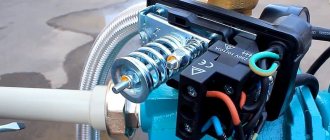
Now let’s get closer to how the relay itself looks and works. The basis is a mechanism operating on a hydraulic principle. This is a sensitive membrane that is attached to metal springs - one larger, the other smaller. When the pressure increases, the thin partition transfers stress to the metal base. The spring mechanism, in turn, is connected to the electrical unit. It consists of two terminals. When the spring is pressed, they close the contact and then open it. This turns the pump on and off.
It is important to note two points about the device:
- All electrical parts are reliably protected from moisture and are located under a special cap at the top of the sensor. The cable is inserted exactly under the terminals, it is also insulated from any liquid.
- The outlet of the hydraulic unit, that is, the membrane cover, is located on the rear side. There is also a mount here. It can be a classic threaded one, which is sometimes not very convenient, or with a union nut.
Design
A pumping station pressure switch is an electronic-mechanical device that starts and turns off the pump at certain pressure values in the water supply network.
Relays produced by various manufacturers are structurally very similar; the differences, as a rule, lie in minor details. The pump is supplied or turned off by closing and opening the contact group - the main element of the relay.
In addition to it, the device includes a piston with a membrane and two springs, which in most cases have different sizes.
After connecting the relay to a special adapter of the pumping station, water pressure begins to act on the membrane, and that on the piston, which is connected to the contact group.
On the opposite side, a large spring acts on the contact group, the compression force of which can be adjusted using the appropriate nut.
If, due to water intake, the pressure in the water supply system drops, the spring overcomes the impact from the piston and the contact group closes, supplying power to the pump.
As the pressure in the pipeline increases, the piston will gradually shift the platform with contacts, overcoming the resistance of the spring. But the contacts do not open immediately, but only after moving a certain distance, which depends on the degree of compression of the second - small - spring. Like the big one, it is mounted on a rod with a nut. After opening the contacts, the pump is switched off.
Design of a typical pressure switch for a pumping station
Thus, by adjusting the compression force of the larger spring, the user sets the pump activation pressure or, as it is also called, the lower pressure - Pon. To set the shutdown pressure (upper) - Poff - a small spring is used, the compression force of which actually determines the difference between Poff and Pon.
At the pre-sale preparation stage, the manufacturer configures the relay. Pon is usually set in the range of 1.5 - 1.8 atm (or bar, which is the same thing), Poff - in the range from 2.5 to 3 atm. If the settings are not suitable for the user or they are incorrect, they resort to adjusting the relay.
However, before doing this, it is necessary to prepare a storage tank.
To organize an independent water supply in the presence of a well, it is necessary to connect a pumping station. Pumping station for a well - types and features, operating principle of the device.
What is a drainage pump and what are the advantages of float options, read here.
A caisson is a device that promotes uninterrupted water supply. Here https://aquacomm.ru/vodosnabzenie/zagorodnyie-doma-v/avtonomnoe-vodosnabzhenie/istochniki/kesson.html you will learn what types of caissons there are and how to install them on a well with your own hands.
Types and varieties
The design may differ from that described above due to other types. All products must first be classified into:
- Mechanical models. Its device is just described above. These are two springs, a movable membrane partition and a block with contacts. It is worth noting such advantages as the stability of the mechanism, as well as its simplicity. And the simpler the design, the less likely it is to break and the easier it is to repair. Therefore, the part can be called quite easy to handle. If there is a “dry running” sensor, that is, a complete shutdown of the equipment in the absence of liquid, then restarting is done manually. It is worth noting that on mechanical water pressure regulators for the pump, precise adjustment is more difficult.
- Electric models. They are distinguished by increased accuracy of values and ease of setup. They have a slightly higher cost. At the core is a flow controller. It is he who transmits the impulse to stop the pumping equipment. An additional advantage is the additional presence of a small hydraulic tank. This fluid supply helps protect the entire installation from water hammer. However, there is also a negative feature - increased sensitivity to impurities. If you install an electric relay, then you must install filters in front of it. Filtration equipment can be ordered from – we supply products for domestic and commercial use.
Another constructive distinction is that the sensor can be:
- Powerful. It carries out the process of activating and switching off the pump.
- Managers. They only transmit information and are also responsible for the operation of the pumping station.
In addition to design features and purpose, all relays can be distinguished by technical indicators:
- according to the maximum achieved pressure in the water utility;
- along the lower similar border;
- according to the volume of the hydraulic accumulator with which the device is compatible;
- by power - this parameter must be correlated with the throughput capacity of the equipment;
- in terms of manufacturer - Russian and Chinese models are not always inferior to European ones, but it is worth highlighting countries of production such as Denmark, Germany, Italy.
Here is a comparison table of popular models:
| Country of Origin | Name | Protection class, IP | Cost, rub. | Lower and upper limits of pressure, atm | Initial setting, atm |
| Italy | Italtecnica РМ/5G (m) 1/4″ | 44 | From 1 900 | 1 –5 | 1,4–2,8 |
| Germany | Grundfos (Condor) MDR 5-5 | 54 | From 3 800 | 1,5 – 5 | 2,8– 4,1 |
| Italy | Italtecnica PT/12 (m) | 44 | From 1900 | 1 –12 | 5 – 7 |
| Spain | Genebre 3781 1/4″ | – | From 500 | 1 – 4 | 0,4 – 2,8 |
| Italy | Italtecnica PM53W 1″ | – | From 500 | 1,5 – 5 | – |
| Russia | RDM-5 Gilex | 44 | From 900 | 1 – 4,6 | 1,4 — 2,8 |
Design and principle of operation of the pressure switch of the pumping station
The pressure switch that comes with the pumping station monitors the volume of water in the hydraulic accumulator and, if necessary, “turns on/off” the hydraulic pump. If the tank is empty, the automation starts it. And then, when the set fill level is reached, the relay turns off the pump again. This way, the required pressure is automatically maintained in the cottage water supply; human participation in this process is not required.
A typical pumping station control relay consists of:
- Housings;
- Two springs (each with an adjusting nut);
- Flange for connecting to a tee on the water supply;
- A membrane that responds to changes in water pressure in the system;
- Contact plate that switches the power supply circuit of the hydraulic pump;
- Power and ground terminals.
Diagram of the internal elements
The pump station relay springs are designed to set the parameters for switching on and off pressure. The large one is responsible for setting the lower threshold of operation, and the small one located nearby is responsible for the upper limit of stopping operation. The first “turns on” the pump, and the second “turns off” it.
Without such automation, the equipment pumping water will have to be constantly turned on and off manually. These pros and cons of a pile foundation and other options must be carefully weighed in order to choose the optimal foundation for the cottage. With a relay that controls the water pressure of the pumping station, everything is much simpler. It is necessary by definition.
In the initial state, the large spring exerts maximum pressure on the plate, which leads to the closure of the contacts of the circuit supplying the pumping equipment. The pump motor begins to receive power. When the upper pressure threshold is reached, the plate rises under the simultaneous pressure of a small spring and a membrane, after which the circuit opens.
And then water is consumed. As a result, the pressure decreases and the membrane contracts. The plate again closes the contacts that supply power to the pump. The pumping station operation process begins in a new cycle.
How to set the pressure on the relay depends on the operating principle
It all depends on what kind of installation we have in front of us - mechanical or electrical. Since in most cases it is the mechanics that are purchased (it is quite accurate and more affordable), let’s talk about it.
MBFT-75 Membrane for 75GPD
SF-mix Clack up to 0.8 m3/h
SF-mix Runxin up to 0.8 m3/h
An individual water treatment and water supply installation is most often installed on a private plot of land. It consists of a well, pumping equipment, a pipeline and a hydraulic accumulator with a sensor. The tank collects liquid, which is then consumed. This allows you to achieve an uninterrupted supply of liquid, as well as a stable pressure. In addition, a serviceable relay allows you to reduce the number of times the equipment is turned on, thereby extending its service life.
The operating principle of the equipment is as follows:
- The hydraulic accumulator runs out of fluid, and at the same time the pressure drops below the Rstart parameter, for which a large spring is responsible. Its pressure on the membrane displaces the terminals and closes them.
- The installation is operating, liquid fills the storage tank. As a result, the indicator increases and exceeds the specified parameters - P stop. A small spring acts on the membrane partition and opens the contacts. The fluid supply stops.
- When a resource is consumed (someone opened a tap in the house, turned on household appliances), the release is activated again to maintain a constant amount of H2O in the tank.
This determines how to adjust the pressure switch at the pumping station, that is, what maximum and minimum settings to set. If there were no sensor, then this on and off cycle would have to be done manually.
Preparation of the pumping station
When organizing individual water supply, special equipment is installed - a pumping station. It consists of two parts:
- submersible (surface) pump;
- hydraulic accumulator
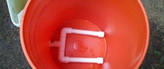
A sealed tank with a rubber membrane installed inside serves to store a supply of water and maintain stable pressure in the system. Before you start setting up the pressure switch of the pumping station with your own hands, you should prepare the tank. The tank consists of a rubber bulb into which water is pumped and a chamber filled with air. The amount of air pressure affects the operation of the entire water supply system, so setting up a pumping station is necessary.
Preparation of the membrane tank begins with completely draining the water from the pipeline and the tank itself. For this purpose, the bottom tap of the system is used. Air is pumped into the empty tank; its pressure should be 10% less than the lower limit. The minimum pressure value is determined depending on the size of the accumulator:
- 20-30 l – 1.4-1.7 bar;
- 50-100 l – 1.8-1.9 bar.
After determining the pressure in the storage tank, the system is immediately filled with water; the rubber bulb must not be allowed to dry out.
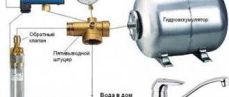
Pumping station with hydraulic accumulator and sensor
Attention. Self-checking the pressure in the tank is necessary when assembling equipment from individual parts. Modern models of pumping stations, manufactured in the factory, have ready-made settings specified in the documents.
In order for the tank membrane to serve for a long time, it is recommended to set the pressure in the storage tank to 0.1-0.2 atm. lower than the minimum level in the system.
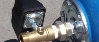
Connecting equipment
During installation you will have to work with two systems. It is equally important to make the correct connection to both the electrical and plumbing. The installation will not move, so the place can be equipped as a stationary one, having previously provided easy access for repairs/maintenance.
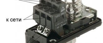
Electrical part
It is best to allocate a separate line; this will extend the life of the device, however, this is not necessary. The copper cable must have a cross-section of no less than 2.5 mm. The sensor itself consumes little electricity, so the voltage value primarily depends on the power of the pump. You will definitely need to ground it, because the electricity + water set is not the safest option. You can follow this scheme when connecting:
When you open the cover on the back of the device, you will see three groups of contacts:
- Ground wires.
- “Line” for phase and zero, coming from the shield.
- The same contacts, but from pumping equipment.
When you have familiarized yourself with the schematic image, perform the standard actions - stripping the conductors, placing their edges in the connector, tightening the fastener. After half an hour or an hour, it is better to try tightening the bolts again, because the copper cable has some ductility.
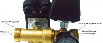
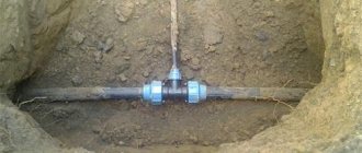
Pipeline connection
This can be done in several ways, but most often a five-pin fitting is used as an adapter. If you don’t have a ready-made device at hand, you can assemble a similar part from classic fittings.
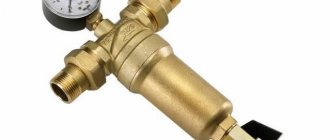
The pipe is attached to the relay body (there is an inlet at the bottom, under the membrane and springs), and the remaining holes are designed to connect the accumulator, hose and main water line. The last outlet can be used for a filter or pressure gauge. With it, setting up a water pressure switch for a pump in a water supply system becomes simple, since it is easier to adjust the sensor not by eye, but by the exact indicators of the device. And it is best to order complex filtration equipment.
What parameters should I set the water supply station to?
When the system is first started, the pressure gauge readings are remembered at the moments when the pump is turned on and off. Look at the product data sheet for the maximum pressure values in the water supply system. Typically they are in the range of 1.5-3 bar.
If you decide to change the settings, you first need to understand whether the pressure needs to be reduced or increased. In order for water to flow out of the taps more intensively, the shut-off pressure should be increased, and vice versa.
Guidelines for determining the new operating range of the pressure gauge:
- the maximum volume of water that happens to be used;
- previous pressure;
- pipe diameter;
- number of pump connections per hour.
Approximate fluid consumption from different consuming devices:
- washbasin - 360 kg/h;
- shower - 600 kg/h;
- toilet - 250 kg/h;
- washing machine - 600 kg/h;
- dishwasher - 500 kg/h;
- irrigation system - 1000 kg/h.
Having calculated the expected water flow, the easiest way is to use the table below to determine the pressure value at which to start regulating:
The pump activation pressure must be no less than 110% of the air pressure in the accumulator.
When automation needs to be reconfigured
Sometimes equipment breakdowns or errors occur. Here are the most common:
- the liquid flow is not powerful enough due to the large suction depth;
- the pump impeller is worn out;
- seals are cracked or dried out;
- difficulties when supplying liquid to the upper floors of a high-rise building or to a tank that is mounted too high.
AMETHYST - 02 M Residential building for up to 10 people or up to 2 cubic meters/day.
Aeration unit AS-1054 VO-90
Main table dispenser AquaPro 919H/RO (hot and cold water)
In such situations, you will need to change the settings set by the manufacturer.
Preparation for the process
What you need to do first:
- fix problems with all water supplies;
- check the indicators in the expander chamber, everything should be adjusted to the lower limit on the relay;
- if necessary, pump up the air - in this case, excess liquid may spill out, this is normal.
What characteristics should be changed?
You can change two parameters:
- RStart.
- Δ P, that is, the difference between the upper and lower limits.
If you do not change the factory value of ΔP (usually it is equal to 1 atm), then when you move Pstart, at the same time Pstop changes by the same amount. Here is a table with the most common problems and options for how to configure the water pump relay:
| Situation | What are we moving? | How |
| Excessively frequent station startup | Increase Rstop | Compress the spring ΔР |
| Pump on too long | The stopping limit needs to be lowered | We lower ΔР while maintaining the starting point |
| The pressure is too high | Reducing Rpusk | We weaken the large spring, and the lower pressure limit automatically tightens |
| Water flows into the taps in a weak stream | Raise Rstart, leave Rstop in the same place | To do this, compress P, weaken ΔP |
Setting up from scratch
Sometimes you have to deal with a relay whose springs are completely weakened. In this case, do this:
- By turning on the pump, the pressure in the network is pumped up to the level at which water flows from the most distant or highly located tap with acceptable pressure. Suppose the pressure gauge showed 1.5 atm. After this, the pump must be turned off.
- After disconnecting the station from the power supply and removing the cover from the relay, tighten the large spring until the relay clicks, closing the contacts.
- Having closed the relay, turn on the pump and increase the pressure to 2.9 atm (1.5 + 1.4).
- Turning off the pump again and opening the relay, tighten the small spring until the contacts open.
- Now the relay is set to Pon = 1.5 atm and Poff = 2.9 atm. It is necessary to close it with a lid and turn on the station to the electrical network.
Setting up the pressure switch
Adjustment instructions
One of the most classic devices is the RDM-5 modification. From the factory it comes with settings of 1.4 atm and 2.8 atm. This is usually enough to install a house, but if you plan to install a jacuzzi, then the pressure should be higher.
There are two springs. The large one is for adjusting the upper and lower limits, and the small one is for changing the delta. You can change these parameters by tightening the nuts at the base (the pressure increases), or by unscrewing it - it becomes lower. If you do this with your hands and without measuring instruments, then usually one full revolution is equal to about 0.7 atm.
How to determine relay response thresholds
Usually they correspond to those stated in the instructions. But if the factory settings have been corrected or high accuracy is important to you, then testing can be done. To do this, remove the top cover, there will be a nipple there. You can connect a measuring device to it - a pressure gauge.
Setting up the pressure switch
During the assembly of the pumping station, special attention is paid to setting the pressure switch. The ease of operation of the water supply system, as well as the trouble-free service life of all components of the device, depend on how correctly its limit levels are set.
At the first stage, you need to check the pressure that was created in the tank during the manufacture of the pumping station. Typically, at the factory, the switch-on level is set at 1.5 atmospheres, and the switch-off level is 2.5 atmospheres. They check this with an empty tank and the pumping station disconnected from the power supply. It is recommended to check with an automotive mechanical pressure gauge. It is housed in a metal case, so the measurements are more accurate than using electronic or plastic pressure gauges. Their readings can be affected by both the room temperature and the battery charge level.
It is desirable that the pressure gauge scale limit be as small as possible. Because on a scale of, for example, 50 atmospheres, it will be very difficult to accurately measure one atmosphere.
To check the pressure in the tank, you need to unscrew the cap that closes the spool, connect the pressure gauge and take a reading on its scale. The air pressure should continue to be checked periodically, for example once a month. In this case, the water must be completely removed from the tank by turning off the pump and opening all taps.
Another option is to carefully monitor the pump shut-off pressure. If it increases, this will mean a decrease in air pressure in the tank. The lower the air pressure, the greater the supply of water can be created. However, the pressure spread from a completely filled to an almost empty tank is large, and all this will depend on the preferences of the consumer.
Having chosen the desired operating mode, you need to set it by bleeding off excess air, or pump it up additionally. It must be borne in mind that the pressure should not be reduced to less than one atmosphere, nor should it be over-pumped. Due to the small amount of air, the rubber container filled with water inside the tank will touch its walls and be wiped. And excess air will not make it possible to pump in a lot of water, since a significant part of the tank’s volume will be occupied by air.
Lower pressure threshold
If the consumer is not satisfied with these values, then knowing how to adjust the pressure in the pumping station, they can be changed. Having figured out how to set the correct pressure in the storage tank, we begin to adjust the sensor settings:
- The pump and relay are disconnected from power. All fluid is drained from the system. The pressure gauge is at zero at this moment.
- The plastic cover of the sensor is removed using a screwdriver.
- Turn on the pump and record the pressure gauge readings at the time the equipment is turned off. This indicator is the upper pressure of the system.
- The tap furthest from the unit opens. The water gradually drains and the pump turns on again. At this moment, the lower pressure is determined by the pressure gauge. The pressure difference to which the equipment is currently set is calculated mathematically - by subtracting the results obtained.
Attention. To obtain the correct setting, you need a reliable pressure gauge whose readings you can trust.
Having the opportunity to estimate the pressure from the tap, select the required setting. Adjustment to increase the pressure of the pumping station is carried out by tightening the nut on a large spring. If the pressure needs to be reduced, the nut is loosened. Do not forget that adjustment work is carried out after disconnecting the device from the power supply.
Attention. The setting is carried out carefully; the relay is a sensitive device. One turn of the nut changes the pressure by 0.6-0.8 atmospheres.
Upper pressure threshold
To set the optimal frequency of pump activation, it is necessary to adjust the pressure difference. A small spring is responsible for this parameter. The optimal value of the difference between the upper and lower pressure thresholds is 1.4 atm. If it is necessary to increase the upper limit at which the unit turns off, then turn the nut on the small spring clockwise. When decreasing - in the opposite direction.
What effect does this adjustment have on the equipment? A reading below average (1.4 atm) will ensure a uniform supply of water, but the unit will turn on frequently and quickly break down. Exceeding the optimal value promotes gentle use of the pump, but the water supply will suffer due to noticeable pressure surges. The pressure difference of the pumping station is adjusted smoothly and carefully. The result of the impact requires verification. The scheme of actions performed when setting the lower pressure level is repeated:
- All devices are disconnected from the electrical network.
- Water is drained from the system.
- The pumping equipment is turned on and the result of the adjustment is evaluated. If the performance is unsatisfactory, the procedure is repeated.
There are limitations to consider when making differential pressure settings:
- Relay parameters. You cannot set the upper pressure threshold equal to 80% of the maximum value of the device. Data on the pressure for which the controller is designed are present in the documents. Household models usually withstand up to 5 atm. If it is necessary to increase the pressure in the system above this level, it is worth buying a more powerful relay.
- Pump characteristics. Before choosing an adjustment, you must check the equipment specifications. The unit should turn off at a pressure of 0.2 atm. below its upper limit. In this case, it will function without overload.
Settings
Sequencing:
- Connect the pressure gauge.
- Turn on the system and note on the device at what values it turns on and off.
- Tighten the nuts on the springs.
- Perform a test run again.
Main table dispenser AquaPro 929CH/RO (cooling/heating)
Floor dispenser AquaPro 311 (empty, without cooling)
Floor-standing dispenser AquaPro 6207CH (cooling/heating/room temp.)
This cycle can be performed several times until the most accurate results are obtained.
Accumulator pressure
It is formed due to the fact that the liquid presses on the membrane. Because of this, the air in the second part of the tank is compressed and puts more pressure on the body. To adjust this indicator, gas can be deflated or inflated through a regular nipple in the design, like in a car tire. Before connecting the relay, be sure to check and adjust the necessary indicators in the hydraulic tank. It should be equal to 1.5 bar.
Idling
The situation in which there is no water in the system and the RD is operating is called idle speed (hereinafter referred to as idling). The electronic versions of the device have a special water pressure sensor in the water supply system, which monitors the presence of water in the pipes and prohibits the operation of the pump (and the pump, respectively) if it is not there.
The mechanical version of the device does not have such a sensor, so it should be installed additionally so that the RD does not operate in idle mode (otherwise its service life will be significantly reduced).
The XX controller may not be installed in a mechanical RD, but then you need to be sure that there will always be water in the system and the pump will never run empty.
It is worth noting that an additional water sensor on a mechanical relay is required only for devices with a wet rotor.
The safety relay must deactivate the RD in the absence of water flow in the pipes. The engine should only turn on when there is a flow of a certain force.
Water sensor device Source zuni.manekido.ru.net
See also: Catalog of companies that specialize in the development and implementation of water supply schemes
Mechanical water control sensor is a complex design that includes three relays:
- two delay devices;
- one flow rate controller.
If the flow relay detects its absence, the delay relay is activated. If it counts the required number of cycles, and the flow switch does not detect the appearance of water during this time, the RD is turned off (the contacts open, the power from the pump is turned off, the engine stops).
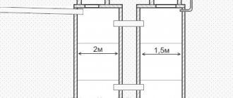
Choosing the right connection diagram
The installation will definitely contain the elements shown in the picture. The connection will be made in this order:
- Water intake point (city pipeline or individual well).
- Filter.
- Hydraulic accumulator.
- Sensor.
- Additional filtration system.
- Faucet or other sources.
Manufacturer's choice
Above we have presented a specific list of models. Based on them, you can make a choice. Important criteria will be:
- Country of Origin;
- price;
- maximum and minimum limits.
Should we consider electronic analogues?
This is a more expensive alternative that is more accurate. This will be relevant in cases where the water supply network includes expensive equipment, plumbing equipment, as well as at production facilities.
Using a relay without a hydraulic accumulator
For some equipment models, a connection diagram for a well pump with a pressure switch without a storage tank is used. A special automatic controller starts and stops the unit when the limit values are reached. The electronic unit has a dry-running protection function and ensures safe operation of the system.
Attention. The disadvantage of this scheme is the lack of a minimum water supply, which is provided by the membrane tank.
Electronic pressure switch for surface and submersible pump
The device starts the pump when the tap is opened; after stopping the water supply, the equipment works for some time to create the preset pressure level. Advantages of an automatic controller:
- compactness;
- the cost of purchasing a hydraulic accumulator is eliminated;
- stable pressure in the system.
Among the disadvantages is the frequent activation of the pump, leading to premature wear. This type of automation is suitable for a network used for long-term switching mode (watering, filling a large container).
Installation and correct adjustment of the pressure switch of the pumping station ensures stable water pressure in the system. Correct adjustment of the device helps to extend the life of the equipment and prevents the occurrence of emergency situations.
conclusions
We have explained in detail what the structure of a hydraulic accumulator is, and why using it without a qualifier is a bad idea. They also gave detailed instructions for installing the equipment. You can make it yourself at home. To adjust the indicators you will not need any special knowledge or special items. After you unscrew the cover of the device with a screwdriver, everything else can be done manually. We hope that our article was useful and now you know how to correctly adjust the water pressure relay (sensor) for the water pump at the pumping station and in the home water supply system.
Malfunctions of the pumping station
During operation of the pumping station, various malfunctions may occur in its operation, the cause of the disturbances is incorrect switching on/off of the electric motor.
The need to replace the relay
Replacement is performed in the following order.
Turn off the power and completely drain the water from the accumulator. Leave the taps in the open position.
After this, close all water taps or the main outlet valve, turn on the pump and fine-tune the water pressure according to the algorithm described above. Never rush. The work is simple, but the consequences of mistakes can be very sad.
The pump constantly turns on/off
This means that the water pressure rises sharply to maximum values, and the engine turns off. The pressure drops just as sharply to the minimum and the unit turns on again.
In this case, there is no need to touch the pressure switch, it is not to blame. The reason is in the hydraulic accumulator - the rubber membrane located inside the cylinder is torn or greatly stretched. It does not expand, does not accept water and does not compensate for increased pressure.
As you know from school physics lessons, water does not compress. When the pump is turned on, the pressure instantly rises, and when turned off it also immediately drops. You will have to disassemble the accumulator and change the membrane.
For normal operation of the pump, it is recommended to set the air pressure in the metal cylinder approximately 10% lower than the switching parameter of the electric motor. The pressure is checked only after the water has completely drained from the accumulator. If it is, then the values rise and distort the adjustment indicators.
The pump does not turn off for a long time
At first everything was fine, and then this problem appeared. The reason is the wear of the pump; it can no longer create the required pressure. The adjustment is simple - slightly reduce the maximum value until the pump turns off. To have a safety margin, it is recommended to further reduce the pressure by a few tenths of an atmosphere. If, as a result of adjustment, the indicators drop to critical levels, then the water pump will have to be replaced.