Home / Boiler automation
Back
Published: 06/11/2019
Reading time: 2 min
1
3927
Modern heating boilers are equipped with electrical devices for ease of use and increased functionality. One of these is a water flow sensor for a gas boiler. The three best models, possible malfunctions and methods of application are discussed further in the article.
- 1 Where used 1.1 For gas boilers
- 1.2 For pumps
Design and principle of operation
A water flow sensor is a device that monitors the pressure inside the water supply system; it is connected to the pump via pipes.
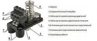
Standard circuit of a water flow sensor:
- relay;
- set of plates;
- There is a wide chamber inside the device;
- a small float, which is placed inside a stationary flask;
- outlet feed channel;
- Most models are equipped with an adjustment valve installed at the outlet.
The principle of operation of the sensor: when there is no liquid flow, it automatically pauses the pumping station and does not allow dry running, and when water appears, it starts the device.
Sensor types
Today, the most popular and advanced water flow devices are reed switch relays and Hall sensors.
Description:
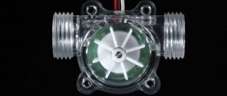
- A flow meter or Hall sensor is a small turbine with a magnet. As soon as the turbine begins to rotate, the magnet creates a field and generates electrical pulses that are transmitted to the boiler board (for example, Ferroli).
- The reed switch regulator also uses magnetism. A float magnet is installed inside the chamber. As soon as the water pressure increases, the float moves and begins to act on the reed switch (several magnetic plates that move apart under the influence of the float).
Application area
Water flow sensors are usually found in devices where it is necessary to constantly monitor the life support system and observe a certain operating mode.
Most often, water flow sensors are used in boilers operating on gas. Modern gas boilers equipped with such sensors are used for both heating and water heating.
The device, which is located on the tap water supply pipeline, when water enters, sends a signal to the boiler control board and the operation of the circulation pump stops. Then the board turns on the nozzles responsible for heating the running water, and the water in the heat exchanger begins to heat up. When the tap closes, the sensor notifies that the water supply has been stopped.
Most households are equipped with autonomous water supply systems, thanks to which you can have the most comfortable conditions.
The function of the water flow sensor is that when you turn on any of the devices connected to the water supply system, the sensor turns on the pump and water begins to flow.
When choosing a water flow sensor, be sure to consider the throughput of the devices and their size.
Recommendations for installation and configuration
Liquid flow relays are installed for devices that require constant control and compliance with a certain operating mode. Often they are equipped with equipment at the production stage. However, there are also circumstances when a separate installation of the sensor is required.
Rules for installing relays in the system
Installing a safety device that detects the presence or absence of water flow in the system is a reasonable step in cases where it is not possible to be present while the pumping equipment is operating.
It is not required only in two cases:
- Water is pumped from a large well with unlimited resources by a low-power pump.
- It is possible to independently turn off the installation when the water level drops below the designated norm.
The device is installed on horizontal sections of the pipeline. In this case, you need to ensure that the membrane assumes a stable vertical position.
The device is mounted to the drain pipeline using a threaded coupling. Usually a special socket is provided for this.
Before you start directly screwing the device, it is advisable to seal the threads well with flax or thread, sold in specialized departments.
It is better to wind it clockwise towards the end. This method of fastening increases the reliability of fixation.
When installing a factory sensor, you need to focus on the arrow shown on the body. The direction indicated on it must coincide with the direction of flow of the liquid passing through the device.
If contaminated water is transported through the pipeline, it is recommended to install cleaning filters, placing them near the sensor. Such a move will ensure the correct operation of the product.
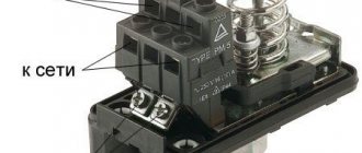
At the final stage of installation work, the dry-running relay is connected to the electrical network:
- a wire core is screwed to the free ends of the two groups of contacts;
- a ground connection is attached to the sensor screw;
- the device is connected to the pump by connecting two devices with a regular wire, matching the colors of the cores.
After connecting to the network, all that remains is to check the functionality of the system. The fact that the device is ready for full operation will be indicated by an increase in pressure marks on the pressure gauge and the automatic shutdown of the pump when the limit value is exceeded.
Self-adjustment procedure
For adjustment, the sensor has special bolts. By loosening or tightening them, you can reduce or increase the compression force of the spring.
This sets the pressure level at which the device will operate.
In most cases, setting up automatic equipment is not difficult.
It is advisable to adhere to the following algorithm:
- drain the liquid from the system until the pressure mark reaches zero;
- turn on the pumping unit and slowly let the water back in;
- record the flow pressure indicator when the pump is turned off with a sensor;
- start draining again and remember the indicators at which the pumping equipment will start working;
- open the relay and use the adjusting bolt to set the minimum level of compression of the larger spring required to activate the device and start the pump (more compression increases the degree of pressure, less - reduces it);
- in a similar way, adjust the compression force of a smaller spring mechanism, setting the limits of the maximum pressure, upon reaching which the relay measuring the water flow will turn off the pump.
Having completed all the described manipulations, you should make sure that the adjustments made are correct. To do this, the pipeline is filled with liquid and then drained, assessing the sensor’s response when the set values are reached.
If the test result is unsatisfactory, the procedure is repeated.
To ensure that the pipeline through which the liquid passes works properly and stably, regular annual checks of the flow sensors are carried out. If necessary, the operating parameters are adjusted.
Types of water flow sensors
According to the type of design, relay and fitting devices are distinguished. In addition, there are varieties based on pressure levels.
A relay-type water flow sensor is used for pumps with low power. Typically these models are single-chamber. Experts note their low conductivity. Models with a vertical arrangement of plates are available, their maximum pressure is at least 5 Pa.
Protection systems are often used in the P48 series. Thanks to all these indicators, there are practically no water leaks, and such devices are also characterized by good operating stability.
The most widely used water flow sensors for pumps are in-line models. Their plates are usually placed horizontally, and some samples are equipped with two valves. Their maximum pressure is approximately 5 Pa. Protection systems are most often class P58. Conductivity is directly dependent on the size of the fitting.
Low pressure sensors are applicable for pumps with a power of no more than 4 kW. The size of the chamber affects the conductivity. Most often on the market you can find a water flow sensor for a pump with two floats. Their price is low and you can easily choose the right model.
High pressure models are usually produced with one extended fitting, the plates are mounted horizontally. Experts advise installing such samples in centrifugal pumps. Maximum pressure does not exceed 6 Pa, protection system class P70.
You can read about the device and connecting the water pressure switch for the pump here.
Also, according to the mechanism of action, it is divided into:
- a water sensor based on the operating principle of a Hall sensor: it signals not only the flow of water, but also the speed of its flow;
- a reed switch sensor operating on the principle of a magnet: inside it there is a magnetic float, which, as the water pressure increases, moves around the chamber and affects the reed switch.
Design and principle of operation of a reed switch water flow sensor
Conclusions and useful video on the topic
Structure, components and operating principles:
The process of connecting a device in stages:
Learn more about how to adjust the trigger level in a relay:
A relay that controls the flow of water in the pipeline will significantly increase the ease of use of pumps and will extend their service life for a long time. It is highly undesirable to neglect the installation of a safety device, since it not only automates the operation of the equipment, but also protects it to the maximum from possible problems that occur due to idling.
Do you want to install the flow switch yourself, but are a little confused about the instructions? Please ask your questions, and we and our website visitors will try to help you.
Or maybe you have successfully completed the installation and configuration of the device and want to give useful recommendations to other beginners? Write your comments in the block below, add photos of the installation or setup process - your experience will be useful to many home craftsmen.
Source: sovet-ingenera.com
DIY installation and manufacturing
Most water flow sensors are included in the design of the devices, so they need to be installed only in the event of a breakdown and the need to replace them. However, there are cases when the water flow sensor must be mounted separately, for example, if it is necessary to increase the water supply pressure. This is due to the fact that in the central water supply system, the pressure is low and does not reach the norm. And in order to turn on a gas boiler in hot water supply mode, you need good pressure.
In such situations, an auxiliary circulation pump is installed, which is equipped with a water flow sensor. First the pump is installed, and then the sensor. It follows that as soon as water starts flowing, the sensor will turn on the pump and the pressure will begin to increase.
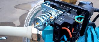
Pressure booster pump for Grundfos UPA 15-90 water supply system with built-in water flow sensor
Making a water flow sensor with your own hands is not difficult. First you need to install the camera, then you need to cut out three plates, they should be mounted horizontally, there should be no contact between them and the bulb. For a simple design, one float will be enough.
It is rational to install the fitting on two adapters; the valve must withstand a pressure of at least 5 Pa.
How to determine the malfunction and make sure that the sensor is to blame
When I measured the sensor resistance with a multimeter, it was 2.5 kOhm. According to the table, it should have such resistance at a temperature of more than 60 degrees, but it was cold. Now it’s clear why the boiler didn’t start in DHW mode, the sensor showed that the water was already too hot, why heat it?
The sensor readings can be variable, so after some time I measured the sensor resistance again and it showed 10 kOhm, which is normal for cold water temperature. The sensor was not stable.
To check my version, I did the following: Disconnected the chip with wires from the sensor. Let's look at the photo.
NTCs sensor location
Instead of the sensor we substitute a resistor
And in the holes of the chip, instead of a sensor, I inserted a resistor with a nominal value of 20 kOhm, with such resistance the “Brains” of the boiler will perceive the water temperature as cold, less than 10 degrees “It needs to be warmed up,” they will think and turn on the boiler. That's exactly how it all turned out.
I start the boiler and... Voila, everything works. Conclusion, you need to change the NTCs submersible sensor.
Since the sensor has direct contact with water, before replacing it it is necessary to turn off the water supply and drain the water from the boiler.
By the way, other errors may occur with this sensor, which will be displayed by the boiler indicator. These are errors such as: 201 - Indicates a break in the sensor or the wires going to it.
202- Indicates that a short circuit has occurred. This could be either the sensor itself or, again, the wires.
Important Conclusion
Substituting a resistor is not a bad way to verify that the sensor is not working. But leaving the boiler to work like this, continuing to deceive the boiler circuit, is not worth it; you still need to purchase a sensor and replace it.
You need to understand that the resistance of the substituted resistor will not change when the water temperature changes, and this sensor, paired with another, regulates the strength of the flame, or rather, from the difference in readings between these sensors, the electronics regulates the strength of the flame. This is how the temperature of the hot water supply is adjusted and protection against scale formation in the heat exchangers.
However, in a pinch you can use a little, for example that evening we all went for a swim, and the very next day I purchased a new sensor and replaced it. If in your city it is not possible to purchase spare parts for the boiler, then this can be done in the Kotlomir online store.
Manufacturers
| Manufacturer | Characteristic |
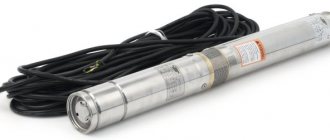
| Water flow sensor for pump Grundfos UPA 120 (Denmark) | Designed to provide water supply to an individual house or apartment equipped with an individual water supply system. The automatic sensor switches on when there is a steady flow of liquid in the range of 90-120 liters per hour. The main function is to protect the pump from idling. The pump starts at a water flow rate of 1.5 liters per minute. The operating voltage of the sensor is 220-240 V. The frequency of current consumption is 50-60 Hz. Maximum current consumption is 8 A. Power consumption is up to 2.2 kW. Operating temperature range: 5-60 degrees Celsius. Degree of protection - IP 65. Price - about 1,800 rubles. |
| Water flow sensor GENYO - LOWARA GENYO 8A (Poland) | Used to control the pump of a domestic water supply system based on actual water consumption. The main feature of the sensor is to monitor the pressure in the water supply during operation. The pump starts at a water flow rate of 1.5 liters per minute. Operating voltage – 220-240 V. Frequency of current consumption – 50-60 Hz. The maximum current consumption is 8A. Power consumption – up to 2.4 kW. Operating temperature range: 5-60 degrees Celsius. Degree of protection - IP 65. Price - about 1,800 rubles. |
| Flow sensor 1.028570 (Italy) | Designed for installation in gas double-circuit boilers of the Immergas brand. Compatible with models: Mini 24 3 E, Victrix 26, Major Eolo 24 4E | 28 4E. Designed for installation in gas boilers of the Immergaz brand, chimney and turbocharged versions. Made in a plastic case with a threaded connection. The Hall sensor 1.028570 allows you to obtain water at a stable temperature at the outlet of the hot water supply circuit. Price - approximately 2,400 rubles. |
Thus, the water flow sensor is designed to protect the operation of boilers and pumping equipment.
Construction of a gas instantaneous water heater
Instantaneous water heaters are compact devices built into the water supply system between the tap and the pipe through which cold water flows.
Entering the heat exchanger, the water begins to heat up and comes out already hot. If you turn the hot valve, the device will turn on automatically, if you close the tap, it will turn off.
The unit consists of the following main elements:
- Control automation.
- Burner.
- Heat exchanger.
A modern geyser has many additional devices that help it operate economically and safely:
- Heat exchanger overheat protection.
- A flow sensor that monitors the water sensor in the heat exchanger.
- A fuse that ensures that there is a flame in the burner and, in addition, protects against emergency gas leakage.
- A draft sensor that monitors the temperature and, if it increases significantly, closes the gas valve.
- Controlling the flame intensity reduces the amount of harmful emissions to a minimum.
- The control unit simplifies the process of monitoring operating parameters such as pressure, power and temperature.
Device selection criteria
When choosing equipment that controls the force of water flow, you should carefully study its technical characteristics.
Particular attention should be paid to the operating temperature and pressure range for which it is designed, the diameter of the threads and mounting holes, the protection class, and application nuances. It is also important to clarify what materials the product is made from.
Experts consider devices made of brass, stainless steel, and aluminum to be the most reliable and durable. These materials protect the structure from the critical consequences of a common phenomenon in water supply systems - water hammer.
When considering different modifications of the relay, it makes sense to purchase a version made of metal. The housing and working components of such devices are highly durable.
This fact allows the equipment to withstand serious loads for a long time that arise due to the significant impact of the liquid passing through the sensor.
The pressure value at which the relay operates must correspond to the power of the installed pump. The parameters of the water flow circulating through the pipeline depend on this characteristic.
It is advisable to choose a device with two springs that controls the operation of the pumping station according to certain lower and upper pressure marks.
The operating temperature range of the sensor directly indicates its possible area of application. For example, models with a high limit temperature are designed for hot water supply circuits and heating systems. For cold water pipelines, a range of up to 60 degrees is sufficient
Another important criterion that deserves special mention is the climatic conditions necessary for the operation of the product. This refers to the recommended air temperature and humidity level that the device needs to provide in order for it to perform at its best.
The maximum permissible load for a particular device is determined by the protection class specified in the technical specifications.
When purchasing a flow sensor, you should check the thread diameter and the dimensions of the mounting holes in the equipment: they must fit perfectly with the pipeline elements. The correctness and accuracy of further installation, as well as the efficiency of the relay after installation, depend on this.
The operating principle of various types of water heating devices
Cumulative
In the case of the accumulative principle of operation, water is heated in a water tank. This type of device for providing hot water is the most common. Their popularity is explained by the attractive price and the lack of specific requirements for electrical wiring.
//www.youtube.com/embed/riDnpWhuKD8
Flow-through
In a flow-through heater, water is heated as it is passed through a special flask equipped with an electric heating element. Such a device is placed directly on the tap with water that comes from the water supply. With this operating principle, the water heats up to approximately 30⁰C. The disadvantages include the fact that a flow-through heater requires a large amount of energy, which is not always possible for old buildings. Based on the power consumed, devices are divided into single-phase and three-phase. In addition, one of the determining factors is the heating element: a spiral or a heating element. If the water in your home or country house is hard, then a spiral heating element is preferable. It is worth noting that the heating element consumes 10–20% less electricity than a device with a spiral.
Video: a little about choosing a water heater
Types and connections to water supply and electricity
Convector heater: pros and cons
There are two main types of instantaneous electric water heaters: pressure and non-pressure. Pressure pumps are also called system pumps and often have the word Sistem in their name. They are connected to a break in the water pipe, as a rule, have greater power and can provide hot water to two or more water points.
Non-pressure or individual instantaneous water heaters are connected like ordinary household appliances - through a flexible hose or a water pipe outlet. They supply one point with heated water, have relatively low power (3-7 kW) and low cost. They exist in different forms:
- in the form of a separate device (most often a rectangular plastic box), which is fixed next to the sink or shower;
- faucet attachments;
- faucet with electrically heated water.
Electric flow faucet for heating water
If you need to wait out several weeks of hot water supply outages, you can install an individual non-pressure electric instantaneous water heater of any type. If a constant supply of hot water is required, it would be more rational to install a pressure unit.
Connecting a pressure water heater to the water supply
Pressure or system electric water heaters are connected to the existing water supply system through a pipe break. They are cut in using a tee, which is installed before the first branch. Shut-off ball valves are installed at the cold and hot water inlet. They turn off the device if there is a centralized hot water supply. These taps are also needed so that, if necessary, the device can be removed for repair or replacement.
Connecting a system electric instantaneous water heater to the water supply
The quality of tap water leaves much to be desired and it is better to install the heater after the filter. If there is no filter at the entrance to the apartment, it is advisable to install it either immediately after the branch to the apartment, or before the water heater.
In a private house, such a unit will work if there is a pumping station or a self-assembled system with a hydraulic accumulator. It cuts in after all the filters, and the output goes to consumers.
Connecting gravity to water
A non-pressure (individual) electric instantaneous water heater of a standard type is connected like a regular household appliance. There must be an outlet from the water supply with a tap and thread at the end. Using a flexible braided hose, the device is connected to the water supply.
How to connect a gravity heater to the water supply
Faucet attachments for heating water are a small group. They are basically screwed onto the threads at the end of the spout (gander). To do this, first unscrew the mesh that is usually installed there.
Faucet attachment for heating water Polaris SMART P 5.5
Some time ago there were quite a lot of them, but they were characterized by low efficiency. The nozzle itself is quite large and you can’t attach it to a low crane—it gets in the way. In addition, taps with electric water heating have appeared on the market, which heat water better, have the ability to adjust the temperature and are more convenient to use. They are installed in place of a regular faucet on a sink or sink. The only difference in installation is the need for an electrical connection.
Electrical connection
Any electric instantaneous water heater is a powerful device and requires a separate power supply line. As an exception, you can connect it to the line that goes to the electric stove - the line is suitable according to the parameters. Only in this case, you need to make sure that the stove and instantaneous water heater do not start working at the same time, otherwise the machine will work due to overload.
The connection of an instantaneous electric water heater is standard - from the panel, the phase from zero is connected to a two-contact RCD (it is necessary to disconnect both phase and zero), then the phase is also connected to the machine and only after that is supplied to the consumer.
Connecting an instantaneous water heater to electricity
The connection itself can be made via a three-pin plug and socket with a mandatory ground connection. You can also install a contact plate or connect a cable directly to the appropriate heater inputs.
Draw the power supply line with a copper wire (solid core):
- up to 7 kW cross section 3.5 mm;
- from 7 to 12 kW - 4 mm.
The machine is selected according to the maximum current consumption (available in the technical specifications). Take the nearest higher rating (if you take the smaller one there will be a lot of unnecessary operations - every time you switch to maximum power). The RCD is taken one step higher in rating, the leakage current is 10 mA.
Read more about the selection of circuit breaker ratings.