What are mechanical properties?
The mechanical properties of aluminum, like other materials, are properties that are associated with the elastic and inelastic response of the material to the application of a load to it, including the relationship between stress and strain. Examples of mechanical properties are:
- modulus of elasticity (tensile, compressive, shear)
- tensile strength (tensile, compressive, shear)
- yield strength
- fatigue limit
- elongation (relative) at break
- hardness.
Mechanical properties are often mistakenly referred to as physical properties.
The mechanical properties of materials, including aluminum and its alloys, that are obtained by tensile testing of the material, such as tensile modulus, tensile strength, tensile yield strength and elongation, are called tensile mechanical properties.
Mechanical properties of aluminum
What are mechanical properties?
The mechanical properties of aluminum, like other materials, are properties that are associated with the elastic and inelastic response of the material to the application of a load to it, including the relationship between stress and strain. Examples of mechanical properties are:
- modulus of elasticity (tensile, compressive, shear)
- tensile strength (tensile, compressive, shear)
- yield strength
- fatigue limit
- elongation (relative) at break
- hardness.
Mechanical properties are often mistakenly referred to as physical properties.
The mechanical properties of materials, including aluminum and its alloys, that are obtained by tensile testing of the material, such as tensile modulus, tensile strength, tensile yield strength and elongation, are called tensile mechanical properties.
Elastic modulus
The modulus of elasticity, often called Young's modulus, is the ratio of the stress that is applied to a material to the corresponding strain in the range where they are directly proportional to each other.
There are three types of stresses and, accordingly, three types of elastic moduli for any material, including aluminum:
- tensile modulus of elasticity
- compressive modulus of elasticity
- shear modulus of elasticity (shear modulus of elasticity).
Table - Tensile elastic moduli of aluminum and other metals [1]
Tensile strength
The ratio of the maximum load before failure of a sample when testing it in tension to the original cross-sectional area of the sample. The terms “tensile strength” and “tensile strength” are also used.
Yield strength
The stress required to achieve a specified small plastic deformation in aluminum or other material under uniaxial tensile or compressive load.
If the plastic deformation under tensile load is specified as 0.2%, then the term “yield strength 0.2%” (Rp0.2) is used.
Figure - Typical stress-strain diagram for aluminum alloys
Elongation (at break)
Often called "relative elongation". An increase in the distance between two marks on a test specimen that occurs as a result of the specimen deforming under tension until it breaks between the marks.
The amount of elongation depends on the cross-sectional dimensions of the sample. For example, the amount of elongation that is obtained when testing an aluminum sheet specimen will be lower for a thin sheet than for a thick sheet. The same applies to extruded aluminum profiles.
Extension A
Percentage elongation after specimen rupture at an initial mark spacing of 5.65 √ S0, where S0 is the initial cross-sectional area of the test specimen. The outdated designation of this quantity A5 is currently not used. A similar value in Russian-language documents is designated δ5.
It is easy to check that for round samples this distance between the original marks is calculated as 5·d.
Extension A50mm
The percentage elongation after specimen rupture, relative to the original length between the 50 mm marks and the constant original width of the test specimen (typically 12.5 mm). In the USA, a distance between marks of 2 inches is used, that is, 50.8 mm.
Shear strength
The maximum specific stress, that is, the maximum load divided by the original cross-sectional area that a material can withstand when tested in shear. Shear strength is typically 60% of tensile strength.
Shear strength is an important quality characteristic of rivets, including aluminum ones.
Poisson's ratio
The relationship between longitudinal elongation and transverse shortening of a section in a uniaxial test. For aluminum and all aluminum alloys in all states, Poisson's ratio is typically 0.33 [2].
Hardness
The resistance of a metal to plastic deformation, usually measured by making an impression.
Brinell Hardness (HB)
Penetration resistance of a spherical indenter under standardized conditions.
For aluminum and aluminum alloys, the hardness of NV is approximately equal to 0.3 Rm, where Rm
– tensile strength, expressed in MPa [2].
If a tungsten carbide indenter is used, the designation HBW is used.
Vickers Hardness (HV)
Penetration resistance of a square pyramid diamond indenter under standardized conditions. Hardness HV is approximately equal to 1.10·HB [2].
Fatigue
The tendency of a metal to fail under prolonged cyclic stress that is well below its tensile strength.
Fatigue strength
The maximum stress amplitude that a product can withstand for a given number of loading cycles. Typically expressed as the stress amplitude that gives a 50% probability of failure after a given number of loading cycles [2].
Fatigue endurance
The limiting stress below which a material will withstand a specified number of stress cycles [2].
Mechanical properties of aluminum and aluminum alloys
The tables below [3] present typical mechanical properties of aluminum and aluminum alloys:
- tensile strength
- tensile yield strength
- tensile elongation
- fatigue endurance
- hardness
- elastic modulus
Mechanical properties are presented separately:
- for aluminum alloys hardened by work hardening.
- for aluminum alloys, hardened by heat treatment.
These mechanical properties are typical. This means that they are only suitable for comparative purposes and not for engineering calculations. In most cases, they are average values for various product sizes, shapes and manufacturing methods.
Source:
- Materials of the German Aluminum Association
- Global Advisory Group GAG – Guidance “Terms and Definitions” – 2011-01
- Aluminum and Aluminum Alloys. - ASM International, 1993.
aluminum-guide.ru
Elastic modulus
The modulus of elasticity, often called Young's modulus, is the ratio of the stress that is applied to a material to the corresponding strain in the range where they are directly proportional to each other.
There are three types of stresses and, accordingly, three types of elastic moduli for any material, including aluminum:
- tensile modulus of elasticity
- compressive modulus of elasticity
- shear modulus of elasticity (shear modulus of elasticity).
Table - Tensile elastic moduli of aluminum and other metals [1]
Determination of elastic modulus and Poisson's ratio
0. INTRODUCTION
The guidelines for laboratory work No. 3 “Determination of the modulus of elasticity and Poisson’s ratio” indicate the purpose of the work, provide the characteristics of the test sample and provide a test procedure.
For better assimilation of the material on the topics: “Tension and Compression” and “Elastic-Mechanical Properties of Materials,” the basic theoretical principles are given that allow one to conduct qualified tests, experimentally determine the values of the elastic constants (E and μ) from one sample test, and analyze the results obtained.
The guidelines end with a list of possible questions when defending a report on this laboratory work.
2. PURPOSE OF THE WORK
Determine experimentally the elastic modulus Ε and Poisson's ratio μ and compare the results obtained with reference data.
3. EQUIPMENT, DEVICES AND TOOLS
Testing machine - MP-0.5. Strain gauge station – TsTM-5. Calipers.
4. CHARACTERISTICS OF SAMPLES
The sample, which has a rectangular cross-section, is shown in Fig. 1. On the large sides of the cross-section of the sample, one strain gauge is glued in the longitudinal direction and one in the transverse direction. Each strain gauge is connected to a separate channel of the strain gauge station TsTM-5.
Rice. 1. View of the image with strain gauges
5. BASIC THEORETICAL PROVISIONS
When the vast majority of materials undergo deformations in the elastic stage, Hooke’s law is valid, which establishes a direct proportional relationship between stresses and deformations:
σ = Ε ε (1)
The quantity Ε is a coefficient of proportionality and is called the elastic modulus of the first kind. Since relative elongation is a dimensionless quantity, the elastic modulus E has the dimension of stress. Hooke's law is valid at voltages not exceeding the proportionality limit apc.
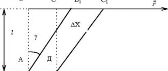
In the tension (compression) diagram (Fig. 2), the elastic modulus E is represented by the tangent of the angle of inclination of the straight line O A to the axis (tan α).
Fig.2. Tension (compression) diagram of a mild steel sample:
- sprains,
- compression
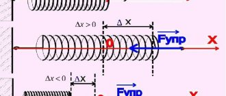
When the rod is stretched, its elongation in the longitudinal direction is accompanied by a proportional narrowing in the transverse direction, as shown in Fig. 3.
Fig.3. Change in sample shape during tensile tests
Longitudinal deformation is usually denoted as follows: absolute – Δi (Δ^ = i\- l),
relative -ε (ε = Δ -£ / ^). We denote the transverse deformation:
absolute – Дь (Ab = bi – b),
relative – ε1 (ε1 = Ab / b). As experience shows ε'= – μ · ε,
where μ is a dimensionless proportionality coefficient, called Poisson’s ratio, the value of which depends only on the material and characterizes its properties. The sign "-" indicates that longitudinal and transverse deformations are always opposite in sign. Poisson's ratio is considered to be a positive value, therefore relative linear deformations are taken in absolute value (μ= ε11 /1 ε |).
6. TEST PROCEDURE
1. Before the test, students need to familiarize themselves with the design of the MP-0.5 machine (first lesson) and the rules of conduct in the laboratory during testing (introductory briefing).
2. Measure the characteristic linear dimensions of the test sample with a caliper.
3. Make sure that the strain gauges are connected to the strain gauge station TsTM-5.
4. Observe the turning on of the machine and the process of loading the sample with an initial load (0 - 100 Η), which is set by the teacher.
5. By sequentially switching the corresponding channels of the strain gauge station, the readings of each of the strain gauges are taken. These data are recorded in the observation log. In the laboratory work report in the “Test Results” section, a table is prepared in advance.
6. Observe the next two loading stages (100 - 200 Η each as directed by the teacher) of the sample, take the readings of the strain gauges and enter them into the table.
7. During the testing process, carefully monitor the teacher’s comments and, upon completion of the testing, upon his instructions, begin processing the test results.
7. PROCESSING OF TEST RESULTS
In the observation log (table), the increments of the corresponding readings are calculated and their average values are determined (АсрР, АсрАь АсрА2, ДсрВь АрВ2). Then the average increments are calculated using strain gauges in the longitudinal (AcrA) and transverse (AcrV) directions.
Based on the found AcrA and AcrB, the values of relative linear deformation are found, respectively, in the longitudinal and transverse directions:
ε = АсрА · с , ε1 = АсрВ · с ,
where c is the sensitivity coefficient of the strain gauge, which is determined by calibration and reported by the teacher.
The value of the normal stress, the average, is determined for each stage of sample loading:
σ = АсрР / F, where F is the cross-sectional area of the sample ( F = b · d).
Based on Hooke’s law under tension-compression (σ= Ε-ε), the elastic modulus of the sample material is found:
Ε = σ/ε.
Based on the found values of relative deformations in the longitudinal and transverse directions, the value of Poisson's ratio is determined:
μ=Η/Ιε|.
For any material, the Poisson's ratio should be in the range from 0 to 0.5.
The found values of the elastic modulus Ε and Poisson's ratio μ should be compared with the corresponding values given in the reference literature and conclusions drawn.
Yield strength
The stress required to achieve a specified small plastic deformation in aluminum or other material under uniaxial tensile or compressive load.
If the plastic deformation under tensile load is specified as 0.2%, then the term “yield strength 0.2%” (Rp0.2) is used.
Figure 4 – Typical stress-strain diagram for aluminum alloys
Young's modulus of elasticity and shear, Poisson's ratio values (Table)
Elastic properties of bodies
Below are reference tables for commonly used constants; if two of them are known, then this is quite sufficient to determine the elastic properties of a homogeneous isotropic solid.
Young's modulus or modulus of longitudinal elasticity in dyn/cm2.
Shear modulus or torsional modulus G in dyn/cm2.
Compressive modulus or bulk modulus K in dynes/cm2.
Compressibility volume k=1/K/.
Poisson's ratio µ is equal to the ratio of transverse relative compression to longitudinal relative tension.
For a homogeneous isotropic solid material, the following relationships between these constants hold:
G = E / 2(1 + μ) - (α)
μ = (E / 2G) - 1 - (b)
K = E / 3(1 - 2μ) - (c)
Poisson's ratio has a positive sign and its value is usually between 0.25 and 0.5, but in some cases it can go beyond these limits. The degree of agreement between the observed values of µ and those calculated using formula (b) is an indicator of the isotropy of the material.
Tables of Young's Modulus of Elasticity, Shear Modulus and Poisson's Ratio
Values calculated from relations (a), (b), (c) are given in italics.
| Material at 18°C | Young's modulus E, 1011 dynes/cm2. | Shear modulus G, 1011 dynes/cm2. | Poisson's ratio µ | Modulus of bulk elasticity K, 1011 dynes/cm2. |
| Aluminum | 7,05 | 2,62 | 0,345 | 7,58 |
| Bismuth | 3,19 | 1,20 | 0,330 | 3,13 |
| Iron | 21,2 | 8,2 | 0,29 | 16,9 |
| Gold | 7,8 | 2,7 | 0,44 | 21,7 |
| Cadmium | 4,99 | 1,92 | 0,300 | 4,16 |
| Copper | 12,98 | 4,833 | 0,343 | 13,76 |
| Nickel | 20,4 | 7,9 | 0,280 | 16,1 |
| Platinum | 16,8 | 6,1 | 0,377 | 22,8 |
| Lead | 1,62 | 0,562 | 0,441 | 4,6 |
| Silver | 8,27 | 3,03 | 0,367 | 10,4 |
| Titanium | 11,6 | 4,38 | 0,32 | 10,7 |
| Zinc | 9,0 | 3,6 | 0,25 | 6,0 |
| Steel (1% C) 1) | 21,0 | 8,10 | 0,293 | 16,88 |
| (soft) | 21,0 | 8,12 | 0,291 | 16,78 |
| Constantan 2) | 16,3 | 6,11 | 0,327 | 15,7 |
| Manganin | 12,4 | 4,65 | 0,334 | 12,4 |
| 1) For steel containing about 1% C, elastic constants are known to change during heat treatment. 2) 60% Cu, 40% Ni. | ||||
The experimental results given below are for common laboratory materials, mainly wires.
| Substance | Young's modulus E, 1011 dynes/cm2. | Shear modulus G, 1011 dynes/cm2. | Poisson's ratio µ | Modulus of bulk elasticity K, 1011 dynes/cm2. |
| Bronze (66% Cu) | -9,7-10,2 | 3,3-3,7 | 0,34-0,40 | 11,2 |
| Copper | 10,5-13,0 | 3,5-4,9 | 0,34 | 13,8 |
| Nickel silver1) | 11,6 | 4,3-4,7 | 0,37 | — |
| Glass | 5,1-7,1 | 3,1 | 0,17-0,32 | 3,75 |
| Glass yen crowns | 6,5-7,8 | 2,6-3,2 | 0,20-0,27 | 4,0-5,9 |
| Jena flint glass | 5,0-6,0 | 2,0-2,5 | 0,22-0,26 | 3,6-3,8 |
| Welding iron | 19-20 | 7,7-8,3 | 0,29 | 16,9 |
| Cast iron | 10-13 | 3,5-5,3 | 0,23-0,31 | 9,6 |
| Magnesium | 4,25 | 1,63 | 0,30 | — |
| Phosphor bronze2) | 12,0 | 4,36 | 0,38 | — |
| Platinoid3) | 13,6 | 3,6 | 0,37 | — |
| Quartz threads (floating) | 7,3 | 3,1 | 0,17 | 3,7 |
| Soft vulcanized rubber | 0,00015-0,0005 | 0,00005-0,00015 | 0,46-0,49 | — |
| Steel | 20-21 | 7,9-8,9 | 0,25-0,33 | 16,8 |
| Zinc | 8,7 | 3,8 | 0,21 | — |
| 1) 60% Cu, 15% Ni, 25% Zn 2) 92.5% Cu, 7% Sn, 0.5% P 3) Nickel silver with a small amount of tungsten. | ||||
| Substance | Young's modulus E, 1011 dynes/cm2. | Substance | Young's modulus E, 1011 dynes/cm2. |
| Zinc (pure) | 9,0 | Oak | 1,3 |
| Iridium | 52,0 | Pine | 0,9 |
| Rhodium | 29,0 | Red tree | 0,88 |
| Tantalum | 18,6 | Zirconium | 7,4 |
| Invar | 17,6 | Titanium | 10,5-11,0 |
| Alloy 90% Pt, 10% Ir | 21,0 | Calcium | 2,0-2,5 |
| Duralumin | 7,1 | Lead | 0,7-1,6 |
| Silk threads1 | 0,65 | Teak | 1,66 |
| Web2 | 0,3 | Silver | 7,1-8,3 |
| Catgut | 0,32 | Plastics: | |
| Ice (-20C) | 0,28 | Thermoplastic | 0,14-0,28 |
| Quartz | 7,3 | Thermoset | 0,35-1,1 |
| Marble | 3,0-4,0 | Tungsten | 41,1 |
| 1) Rapidly decreases with increasing load 2) Detects noticeable elastic fatigue | |||
| Temperature coefficient (at 150C) Et=E11 (1-ɑ (t-15)), Gt=G11 (1-ɑ (t-15)) | Compressibility k, bar-1 (at 7-110C) | |||
| ɑ, for E | ɑ, for G | |||
| Aluminum | 4,8*10-4 | 5,2*10-4 | Aluminum | 1,36*10-6 |
| Brass | 3,7*10-4 | 4,6*10-4 | Copper | 0,73*10-6 |
| Gold | 4,8*10-4 | 3,3*10-4 | Gold | 0,61*10-6 |
| Iron | 2,3*10-4 | 2,8*10-4 | Lead | 2,1*10-6 |
| Steel | 2,4*10-4 | 2,6*10-4 | Magnesium | 2,8*10-6 |
| Platinum | 0,98*10-4 | 1,0*10-4 | Platinum | 0,36*10-6 |
| Silver | 7,5*10-4 | 4,5*10-4 | Flint glass | 3,0*10-6 |
| Tin | — | 5,9*10-4 | German glass | 2,57*10-6 |
| Copper | 3,0*10-4 | 3,1*10-4 | Steel | 0,59*10-6 |
| Nickel silver | — | 6,5*10-4 | ||
| Phosphor bronze | — | 3,0*10-4 | ||
| Quartz threads | -1,5*10-4 | -1,1*10-4 | ||
Elongation (at break)
Often called "relative elongation". An increase in the distance between two marks on a test specimen that occurs as a result of the specimen deforming under tension until it breaks between the marks.
The amount of elongation depends on the cross-sectional dimensions of the sample. For example, the amount of elongation that is obtained when testing an aluminum sheet specimen will be lower for a thin sheet than for a thick sheet. The same applies to extruded aluminum profiles.
Figure 5 – Influence of alloying elements on strength properties and relative elongation [4]
Extension A
Percentage elongation after specimen rupture at an initial mark spacing of 5.65 √ S0, where S0 is the initial cross-sectional area of the test specimen. The outdated designation of this quantity A5 is currently not used. A similar value in Russian-language documents is designated δ5.
It is easy to check that for round samples this distance between the original marks is calculated as 5·d.
Extension A50mm
The percentage elongation after specimen rupture, relative to the original length between the 50 mm marks and the constant original width of the test specimen (typically 12.5 mm). In the USA, a distance between marks of 2 inches is used, that is, 50.8 mm.
Elastic modulus. Poisson's ratio
The question of determining normal stresses is closely related to the strength calculations of timber. stiffness calculations , as well as for determining forces in statically indeterminate systems.
Let us select from the timber shown in Fig. 17.7 infinitesimal element of length dz
.
The ratio of the increment (change) in the length of an element to its original length is called relative elongation or longitudinal deformation :
(17.2)
Obviously, longitudinal deformation is a dimensionless quantity. In some cases it is expressed as a percentage. In tension, the longitudinal strain is considered positive, and in compression, it is considered negative.
The ratio of the change in cross-sectional size to its original value is called relative transverse contraction ( expansion ), or transverse deformation :
(17.3)
Longitudinal and transverse deformations are also called linear deformations .
Within certain loading limits, there is a directly proportional (linear) relationship between (deformation) and the corresponding (acting in its direction) stress.
This position is called Hooke's law and is written in the form
(17.4)
The proportionality coefficient E is called the modulus of longitudinal elasticity (modulus of elasticity of the 1st kind; Young's modulus ). E has the same dimension as stress, i.e. expressed in Pa or MPa.
The longitudinal modulus of elasticity is a physical constant of a given material that characterizes its rigidity. The stiffer the material, the less it deforms at a given stress.
It has been experimentally established that during simple tension or compression, the ratio of transverse to longitudinal deformation is a constant value for a given material. This ratio, taken in absolute value, is called the transverse strain ratio , or Poisson's ratio ;
(17.5)
Poisson's ratio values for various materials range from 0 to 0.5.
The Poisson's ratio has a minimum value for a plug ( = 0); maximum – for rubber (0.5). For most metals and alloys, the value of Poisson's ratio varies within relatively narrow limits: from 0.23 to 0.35 (on average approximately 0.3).
Question about determining the change in length (lengthening or shortening) of a beam. Elongation or shortening is equal to:
(17.6)
Expression (17.6) is often called Hooke’s formula , and the product E∙A is conventionally called the stiffness of the beam section under tension (compression).
The concept of stiffness of a beam (section of a beam) is determined by the formula
(17.7)
The rigidity of a beam is numerically equal to the force causing elongation (or shortening) of the beam equal to a unit of length: 1 m or 1 cm, etc.
When calculating in SI units, the stiffness coefficient is expressed in newtons per meter (N/m).
The reciprocal of the stiffness coefficient is called compliance coefficient :
(17.8)
The compliance coefficient is numerically equal to the elongation (shortening) of the beam caused by a force equal to a unit of force: 1 N or 1 kN.
(17.9)
or
(17.10)
17.4. A special case of a plane stress state is pure shear. Hooke's law under shear.
Let us consider the special case of a plane stress state, for which non-zero principal stresses are equal in magnitude and opposite in sign (Fig. 17.8).
This state of stress is called pure shear . The maximum principal stress should be designated, minimum; by condition, ; intermediate principal stress = 0.
Pure shear is a plane stress state in which, in the vicinity of a given point, an element can be identified in such a way that on its four faces there are only equal tangential stresses.
As an example illustrating the occurrence of pure shear, consider the torsion of a thin-walled pipe (Fig. 17.9 a). From the equilibrium condition of the cut-off part of the pipe, shown separately in Fig. 17.9 b, it follows that in the cross section (any) only one internal force factor arises - torque, numerically equal
external moment M. Tangential stresses ( ) arise in the cross section of the pipe.
Shear deformation . Let us depict an element highlighted by areas on which only shear stresses arise. Considering that we are interested in the deformation of the element, and not its displacement as a rigid body, we will consider one of the faces to be stationary. A measure of shear deformation is the change in the original right angle between the faces of the element, called the shear angle and denoted by . The shift angle is expressed in radians (Fig. 17.10).
There is a direct proportionality between the shear angle and the corresponding shear stress - Hooke's law in shear .
(17.11)
Here G –
elastic constant of a material, characterizing its
rigidity under shear deformation and called shear modulus or modulus of elasticity of the 2nd kind .
The dimension of the shear modulus is the same as the stress. (17.12)
Shear strength
The maximum specific stress, that is, the maximum load divided by the original cross-sectional area that a material can withstand when tested in shear. Shear strength is usually about 60% of tensile strength.
Shear strength is an important quality characteristic of rivets, including aluminum ones.
Figure 6 – Compressive strength, shear strength, load-bearing strength and hardness of various aluminum alloys [4]
Hardness
The resistance of a metal to plastic deformation, usually measured by making an impression.
Brinell Hardness (HB)
Penetration resistance of a spherical indenter under standardized conditions.
For aluminum and aluminum alloys, the hardness of NV is approximately equal to 0.3 Rm, where Rm is the tensile strength expressed in MPa [2].
If a tungsten carbide indenter is used, the designation HBW is used.
Vickers Hardness (HV)
Penetration resistance of a square pyramid diamond indenter under standardized conditions. Hardness HV is approximately equal to 1.10·HB [2].
Mechanical properties of aluminum alloys
Collapsing strength of aluminum alloys
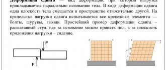
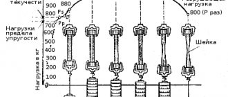
Aluminum's collapse strength is also difficult to determine, test, and relate to conventional strength properties as it is for other metals. Collapse is often an important criterion for structures using rivet and bolt connections and therefore “collapse strength” is a widely recognized characteristic. Bearing strength is very loosely defined as the pressure (per unit effective bearing area) applied by a pin in a circular hole. This hole is preliminarily expanded to 2% of the original diameter (Figure 1). This strength for most aluminum alloys is 1.8 times the tensile strength (tensile strength) (Figure 2).
Picture 1
Figure 2
Shear strength of aluminum alloys
The loading diagram for the shear test is shown in Figure 3. For wrought aluminum alloys, the ratio of shear strength to tensile strength varies depending on the chemical composition and manufacturing method from 0.5 to 0.75 (see Figure 2). In the absence of data on shear strength, it is usually taken as 0.55 of the tensile strength.
Figure 3
Rivets made from aluminum grades and Al-Mn alloys (3xxx series) are produced by cold deformation methods to achieve shear strength of up to 200 MPa. Rivets from thermally hardenable alloys are manufactured in an annealed state, then immediately subjected to hardening and natural aging to achieve a shear strength of up to 260 MPa.
The resistance of a material to local plastic deformation that occurs when a harder body, an indenter, is introduced into it is an approximate indicator of the condition of the alloy and is therefore widely used in product control. For aluminum alloys, the Brinell (steel ball), Vickers (diamond pyramid) and Shore (falling diamond cone) methods are used. Brinell hardness ranges from 20 for pure aluminum to 175 for heat-strengthened 7075 alloy (see Figure 2). According to hardness readings, as a rule, their tensile strength is not calculated, as is usually done for steels, since for aluminum alloys the ratio of these two characteristics is far from constant.
Fatigue
The tendency of a metal to fail under prolonged cyclic stress that is well below its tensile strength.
Figure 7 – Difference in fatigue behavior of low-carbon steel and aluminum alloys [3]
Fatigue strength
The maximum stress amplitude that a product can withstand for a given number of loading cycles. Typically expressed as the stress amplitude that gives a 50% probability of failure after a given number of loading cycles [2].
Fatigue endurance
The limiting stress below which a material will withstand a specified number of stress cycles [2].