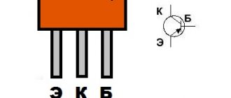
Me and Diode. Entertaining - Tech Blog
After reading a little about amateur radio forums on making metal detectors , I discovered that most people who assemble metal detectors , in my opinion, unfairly write off beat-based metal detectors - the so-called BFO metal detectors . Allegedly, this is the technology of the last century and “children’s toys.” — Yes, this is a simple and unprofessional device that requires certain skills and experience in handling. It does not have a clear metal selectivity and requires adjustment during operation. However, it is also possible to perform a successful search under certain circumstances. As an option, beach searching is an ideal option for a beating metal detector .
Place to search with a metal detector.
You need to go with a metal detector where people lose something. I'm lucky to have a place like this. Not far from my house there is an abandoned river sand quarry, where people constantly relax in the summer, drinking and swimming in the river. It’s clear that they are constantly losing something. In my opinion, there is no better place to search with a BFO . Lost items are instantly buried at a shallow depth in dry sand and it is almost impossible to find them manually. Some kind of mysticism. I remember when I was a child I dropped my apartment keys in the sand there. Here I am standing, the keys fell here, but no matter how much I dug up that area, it was all to no avail. They literally fell through the ground. Just an enchanted place. At the same time, on this “golden” beach, I constantly found other people’s keys, lighters, coins, jewelry and phones in the sand. And on my last trip with a metal detector, I found a woman’s thin gold ring. It was almost at the surface, slightly sprinkled with sand. Perhaps it was just luck. Actually, it was for this beach that I made my metal detector.
Using a metal detector
Professional highly sensitive metal detectors are used in the daily work of various inspection points; they are used to conduct search and investigative activities of police and rescue services.
A huge army of amateur treasure hunters around the world practice long and leisurely hikes with metal detectors. Sometimes such entertainment brings income and even fame.
Nowadays, an industry of detector (recognition) devices has already been established for all occasions, differing not only in operating principles, but also in a wide range of prices and technical characteristics.
Advantages of a beat metal detector.
Why BFO ? — Firstly, this is the simplest version of a metal detector . Secondly, it has at least some signal dynamics depending on the properties of the object. It’s not like a pulse metal detector – it beeps at everything the same way. I in no way want to belittle the merits of a pulse metal detector . This is also a wonderful device, but it is not suitable for a beach littered with corks and foil. Many will say that even a beating metal detector does not distinguish the properties of an object ; it howls and buzzes the same for everything. However, it is not. After practicing on the beach for a couple of days, I became quite good at identifying foil as a sharp and profound change in frequency. Beer bottle caps cause a strictly defined frequency change that needs to be remembered. But the coins emit a weak, “point” signal - a subtle change in frequency. All this comes with experience, patience and good hearing. A beat metal detector is still an “auditory” metal detector . The analyzer and signal processor here is a person. For this reason, you must search on headphones, and not on the speaker. Moreover, the best option is large headphones, not earplugs.
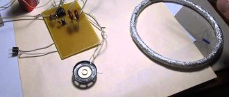
Metal detector design.
Structurally, I decided to make the metal detector foldable and compact. So that it fits into a regular bag, so as not to attract the attention of “normal” people. Otherwise, when you get to the search site, you look like an “alien” or a scrap metal collector. For this purpose, I bought the smallest (two-meter five-legged) telescopic rod in the store. Left three knees. The result was a fairly compact folding base, on which I assembled my metal detector .
The entire electronic unit was assembled in the 60x40 plastic wiring box I already loved. The end cap, the power compartment partition and the power compartment cover were also made from its plastic. The parts were glued together with superglue and mounted on M3 bolts. The electronic unit of the metal detector attached to the fishing rod in the form of a metal bracket, which is inserted into place of the fishing reel with fishing line and secured with the standard nut of the fishing rod. The result is an excellent lightweight and durable design. On the outside of the unit there is a power button, a coil connection socket (a five-pin socket from a “grandfather’s” tape recorder), a frequency regulator and a headphone jack.
The printed circuit board of the metal detector was made on site by routing the tracks with a waterproof marker. For this reason, unfortunately, I cannot provide a seal. Surface mounted mounting - no holes - “lazy” - my favorite. It is also important, after assembling the board, to cover it with any varnish to protect it from moisture and debris. In field conditions this is very important. For example, I lost one day because some debris got inside under the microcircuit. The metal detector just stopped working . And I had to return home, disassemble it, blow it out and open the board with varnish.
Pulse metal detector PI-AR
Pulse metal detector PI-AR on a stm32f103c8t6 microcontroller. The name is taken from the words PI - pulse operating principle, AR - short for ARM microcontroller. The software is developed in the Arduino environment. Metal detector parameters, coin detection, by air, 25 mm to 25 cm, large objects up to 200 cm. The schematic diagram is shown in Fig.
The principle of operation is the same as that of all pulse metal detectors. A short current pulse is applied to the search coil L1, (120 μs in this case) inducing eddy currents in the target. When the pulse is abruptly interrupted, a self-induction EMF appears in the coil and these eddy currents increase the decay time of the self-induction pulse, then the signal is amplified by the analog part and recorded by the microcontroller. The figures show oscillograms, the first without metal in the field of view of the coil, the second with metal. The first channel of the oscilloscope, output from the coil through the limiting circuit R5, D1, D2. The second channel is an input to the microcontroller contact (A0).
The pulse is supplied to coil L1 through transistor T1, which is controlled by chain B9 (contact of the STM32 board), R6, T2, R1, R2. Resistor R5 and diodes D1, D2 limit the self-induction voltage of coil L1 to 2 volts. The analog part is made of operational amplifier DA1 (TL072) and transistor T3, the latter serves to amplify and match levels with a 3.3 volt microcontroller. Next, the signal is sent to the input (A0) of the STM32F103C8T6 microcontroller, where it is captured by a timer from (1) to (0) and after processing the signal, the value is displayed on the indicator. This microcontroller was chosen because of its speed, which in this case is very important (I didn’t want to complicate the analog part when it can be processed digitally), and the support of this board in ARDUINO. The indication is made on a ready-made WS2812B module consisting of eight LEDs and a buzzer with a supply voltage of 5 volts. Control is carried out using an encoder (adjusting sensitivity, brightness, turning off and turning on the buzzer, increasing and decreasing the detection depth and expanding the indication scale.)
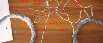
Making a coil
The coil is wound with 0.7 mm wire, on a 200 mm mandrel, 25 turns, then tightly twisted with thread. The reel body is made of PVC sheet, 5 mm thick and glued with glue for PVC pipes.
Barbell
The rod is made of PVC pipes connected with glue. These pipes have good rigidity compared to those that are soldered, and they are lighter in weight.
Software
In the ARDUINO environment, you need to download the library for STM32 boards, then install support for 32-bit CORTEX M3 boards in the board manager. Then select the Generic STM32F103C series board. Select a programmer (I used the ST-LINK programmer). The sketch for the firmware is attached in the archive. Everything is commented in the sketch so everything should be clear.
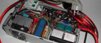
Power supply
As a power source, I used POWER-BANK 10 Ah and a DC-DC boost converter. Since POWER-BANK did not want to work with it, (the protection was triggered) I soldered the wires directly to the batteries, the output was 3.7 - 4.2 volts. In this case must be used EXTREMELY CAREFULLY. a short circuit can cause batteries to explode and prevent a discharge below 2.7 volts (this cannot be done. Additional protection must be installed). Next, we set the voltage at the output of the DC converter to 12 volts. At the moment the power was turned on (while the microcontroller was being initialized), transistor T1 was open and the DC converter did not start; for this purpose, resistor R4 was added.
DC - DC boost converter MT3608.
I installed a power filter here (just in case).
Current consumption during operation is 80 milliamps.
Making a block
To manufacture the block itself, we will need a ready-made board with an STM32F103C8T6 microcontroller, an encoder, a 5-volt buzzer, an LED module of 8 WS2812B LEDs in the form of a strip or circle, and the radio elements indicated in the list.
Diagram of a beat metal detector.
The circuit itself (see below) was redesigned and optimized by me from two metal detector circuits . These are “ Metal detector on a chip ” - Radio magazine, 1987, No. 01, pp. 4, 49 and “ High sensitivity metal detector ” - Radio magazine, 1994, No. 10, p. 26.
The result is a simple and functional circuit that provides stable low-frequency resulting beats - what is needed to determine by ear the slightest changes in frequency.
The stability and sensitivity of the metal detector are ensured by the following circuit solutions:
The reference and measuring generators are separated - made in separate microcircuit packages - DD1 and DD2. At first glance, this is wasteful - only one logical element of the microcircuit package is used out of four. That is, yes, the reference generator is assembled on only one logical element of the microcircuit. The remaining three logical elements of the microcircuit are not used at all. The measuring generator is built in exactly the same way. It would seem that it makes no sense not to use the free logical elements of the microcircuit package. However, this is precisely what makes a lot of sense. And it consists in the fact that if, for example, you assemble two generators in one microcircuit package, they will synchronize each other at close frequencies. It will not be possible to obtain the slightest changes in the resulting frequency. In practice, this will look like a sharp change in frequency only when a massive metal object is close to the measuring coil. In other words, sensitivity sharply decreases. The metal detector does not respond to small objects. The resulting frequency seems to “stick” to zero—up to a certain point, there are no beats at all. They also say “ dull metal detector ”, “dull sensitivity”. By the way, “ Metal detector on a microcircuit ” - Radio magazine, 1987, No. 01, pp. 4, 49 is built on just one microcircuit at all. This effect of frequency synchronization is very noticeable there. It is completely impossible for him to search for coins and small objects.
Also, both generators must be shielded with separate small screens made of tin. This increases the stability and sensitivity of the metal detector as a whole . It is enough to simply solder small partitions made of tin at minus between the generator chips to ensure that the parameters of the metal detector are improved. The better the screen, the better the sensitivity (the influence of the generators on each other is weakened and plus protection from external influences on the frequency).
Electronic tuning.
All classic BFO circuits (BFO circuits of the last century) use a variable capacitor KPI to adjust zero beats This lousy element initially negates all the capabilities of a beat-based metal detector . Never use KPIs in BFO ! Even if it does not have backlash, it will still be a source of parasitic frequency changes due to temperature and capacitive influences of the environment. Searching in real field conditions with a condenser metal detector on beats is pure torture.
Read also: Diode d18 precious metal content
Electronic tuning only! It is implemented using zener diode D1, included in the circuit as a varicap. This scheme provides good frequency tuning in the absence of parasitic phenomena. Instead of KS147, you can use, for example, KS133, KS156 and many others. Also, many diodes have varicap properties. Naturally, you may have to select resistors R1, R3. Perhaps R3 will need to be short-circuited altogether with another zener diode or diode.
Comparator on DD3.2 – DD3.4.
This circuit element converts the sinusoidal signal from the output of the DD3.1 mixer into rectangular pulses of double frequency.
Firstly, rectangular pulses are clearly audible at hertz frequencies as clear clicks. While a sinusoidal signal of hertz frequencies is already difficult to distinguish by ear.
Secondly, doubling the frequency allows the adjustment to come closer to zero beats. As a result, by adjusting you can achieve a “clicking” sound in the headphones, the change in frequency of which can already be detected when you bring a small coin to the coil at a distance of 30 cm.
Generator power stabilizer.
Naturally, in this circuit, the supply voltage noticeably affects the frequency of the generators DD1.1 and DD2.1 of the metal detector . Moreover, each of the generators is affected differently. As a result, as the battery discharges, the beat frequency of the metal detector also “floats” . To prevent this, a five-volt stabilizer DA1 was introduced into the circuit to power generators DD1.1 and DD2.1. As a result, the frequency stopped “floating”. However, it should be said that, on the other hand, due to the five-volt power supply of the generators, as a whole decreased Therefore, this option should be considered optional and, if desired, generators DD1.1 and DD2.1 can be powered from the crown without a DA1 stabilizer. You just have to adjust the frequency manually more often using a regulator.
Pulse metal detector "Pirate"
Greetings, homemade radio amateurs!
I think everyone in life would like to find a treasure - to dig a hole under some lonely tree and find an old chest of jewelry there. It sounds like the plot of a fairy tale, but in fact it is very close to reality - after all, thousands of enthusiasts around the world comb the lands with special devices - metal detectors, in search of valuable antiquities, scrap metal or simply various ancient interesting things. Of course, entire ancient chests are not found on every corner, and sometimes you need to spend more than one year searching for a truly valuable find, but the first time you go searching with the device, you can count on at least coins - at least modern ones. Before us, more than one generation lived on these same lands; over many tens and hundreds of years, a huge number of metal objects fell into the ground, which remain buried - perhaps we walk on them literally every day, especially when it comes to suburban areas, but we simply don’t suspect that there might be something interesting underground. For searching, there are now a large number of different metal detectors on sale, at a variety of prices and with different characteristics, there are even those that are designed for underwater searching and are capable of working at great depths.
Advanced models have discrimination - that is, they immediately show whether ferrous or non-ferrous metal is underground, this is important when searching in littered areas, where the metal detector is triggered by people’s discarded caps and cans literally every couple of meters. Branded devices have a rather complex structure, and therefore have quite decent prices - not everyone can afford to buy a metal detector, especially if it will not be used regularly, but just a couple of times, for the sake of interest. But here radio electronics comes to the rescue - with only a little skill in this area, you can assemble with your own hands a full-fledged device with a fairly high sensitivity, even if it does not discriminate and reacts to all metals in a row, and can be used for searching. We are talking about the “Pirate” metal detector - perhaps one of the most popular circuits for assembly among metal detectors, because it combines many advantages - sensitivity of about 20 cm per coin, simplicity of the circuit, absence of any expensive elements, parts for the entire circuit are available buy it literally for 200-300 rubles, or even pull it out of faulty equipment. The metal detector diagram is shown below.
On the left side of the circuit, a rectangular pulse generator is assembled on the NE555 chip - after all, the metal detector is pulsed. The 100 nF capacitor C1 is a frequency-setting capacitor, so here you can use a reliable capacitor whose capacitance will not change depending on the temperature - any film capacitor will do. Rectangular pulses are removed from the 3rd pin of the microcircuit and through a resistor enter the base of the first transistor T1 - it is a kind of driver for the operation of the powerful field-effect transistor T2. Any low-power PNP structure, for example, BC557 or KT3107, can be used as T1. Powerful field ones are suitable as T2 - for example, IRF740, IRF630 and the like. This transistor switches the search coil with the frequency of the generator, which is approximately 100-200 hertz. The search coil is the only one in the diagram indicated by inductance; its manufacture will be discussed later. Resistor R7 serves to suppress bursts of self-induction from the coil - this resistor is quite important, because the maximum sensitivity of the circuit will depend on it. Its power should be 1W, since it produces a small amount of heat. If the circuit works immediately after assembly, but the sensitivity is rather weak, you can adjust the resistance both up and down, achieving maximum sensitivity. The signal from the coil for detecting the presence of metal is removed from the drain of the field-effect transistor and through a resistor goes to the diode amplitude limiter, these are diodes D1, D2 - here you can use any low-power silicon ones, for example, 1N4148, KD521. And through the isolation capacitor C3, the signal goes to the microcircuit, which issues a signal about the presence of metal. The diagram shows an operational amplifier, but not just any microcircuit can be used here - the only suitable option is the K157UD2, a domestic microcircuit, with which the best sensitivity is achieved. You can also use TL082, but in this case the circuit will be slightly different - this version of the circuit can be found on the Internet. In the wiring of the microcircuit you can see a variable resistor with the designation “sensitivity” - it is used to adjust the threshold of the metal detector. Here it is advisable to use two series-connected variable resistors, one, for example, of 100 kOhm for coarse tuning, and 10 kOhm for fine tuning. The threshold is adjusted as follows: the metal detector with the coil is turned on, and the coil should be located away from metal objects. And by rotating the resistor, a position is established in which the circuit will emit only rare single clicks. Now, if you bring a metal object to the coil, you will immediately hear frequent and intense clicks from the speaker; by their intensity, you can judge the size and depth of the found object. Transistor T3 switches the speaker; any low-power speaker is used here, for example KT3102, BC547. The speaker is low-power, small in size and low power, for example, from some toys, with a resistance of 4-8 Ohms. You can also connect headphones instead of a speaker by increasing the resistance R17, in this case strangers will not hear loud signals, which is very convenient. The entire circuit is assembled on a printed circuit board, which can be downloaded at the end of the article. The board is made using the standard LUT method, then the parts are soldered - first small resistors, then larger components. Please note that after assembling the board, you must wash off the flux from it, because its residual conductivity can disrupt the operation of the circuit and the sensitivity will decrease. In this circuit, the pulse generator was assembled on the NE555 chip, but if it was not at hand, exactly the same generator can be assembled on a pair of transistors, this option is shown in the diagram below.
The search coil is made using enameled copper wire with a diameter of 0.6 - 0.8 mm; it must be wound on a dielectric mandrel with a diameter of about 20 cm - you can vary it to achieve the desired sensitivity. The number of turns is also about 20, the exact number is selected individually based on the best results. The coil must be connected to the board with thick copper wires; it should also be taken into account that there should not be any metal objects in the design of the coil.
The board is installed in a suitable case, a speaker or headphone jack is installed in it, and a variable resistor and a power button are displayed as controls. The supply voltage is 12V, the current consumption does not exceed 12V - it is very convenient to use three lithium-ion batteries connected in series as a power source. Then the entire device can be mounted on a homemade rod for easy searching, it is shown below. Happy building!
imp_tranz.rar [38.66 Kb] (downloads: 341)
Source
Become the author of the site, publish your own articles, descriptions of homemade products and pay for the text. Read more here.
Metal detector coil design.
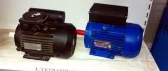
Since this is not a pulse metal detector, but a BFO , the search coil (L2) is not afraid of metal objects in its design. We don't need a plastic bolt. That is, we can safely use a metal (but only open!) frame and a regular metal bolt for the hinge to make it. Subsequently, when setting up the circuit, all the influences of the metal in the structure will be brought to zero by the tuning core of the L1 coil. The L2 coil itself contains 32 turns of PEV or PEL wire with a diameter of 0.2 - 0.3 mm. The diameter of the coil should be about 200 mm. It is convenient to wind on a small plastic conical bucket. The resulting turns are completely wrapped with electrical tape and tied with thread. Next, this entire structure is wrapped in foil (cooking foil for baking). Tinned wire is wound on top of the foil in several turns around the entire perimeter of the coil. This wire will be the output of the foil screen of the coil. Once again everything is wrapped together with electrical tape. The coil itself is ready.
The frame on which the reel will be located and with which it will be attached to the fishing rod is made of springy steel (not soft) wire 3-4 mm. It actually consists of three parts (see figure) - two twisted wire loops of the hinge, which will be connected by a bolt to each other and a wire ring threaded into the tube from the dropper (the ring should not be a closed turn).
This entire structure, together with the finished wire spool, is also tied together with threads and electrical tape.
The joint itself with the reel is attached to the rod by tying it with nylon threads and gluing it with epoxy resin.
It is advisable not to wet the coil during the search process, and especially not to use it for underwater searching. It is not airtight. Moisture that gets inside can destroy it over time.
Coil L1 (see diagram) is wound on a frame from a small-sized radio receiver with a metal screen and a tuning core. The coil contains 65 turns of PEV wire with a diameter of 0.06mm
Finding artifacts underground is a fairly popular activity. For some, this is a profession, others are simply interested in archaeology. There are numerous groups of treasure hunters: both romantics and pragmatic treasure hunters. All these people are united by one passion: searching for metal objects hidden at various depths.
Just because you have an accurate map showing where the treasure is buried, or plans for fighting during the war, this does not guarantee success. You can shovel tons of soil, and the desired item will calmly lie a couple of meters from the active search site.
To search for gold and less valuable metals, you will need a metal detector that you can make yourself.
Important information: The use of such devices is not prohibited by law. However, there are penalties for the consequences of such a search regarding excavations, as well as the recovery of discovered objects.
We won’t go into details; that’s the topic of another article. Simply put: if you find a gold ring on the beach, or a handful of Soviet coins in the forest, there will be no problems associated with the use of electronic search tools.
But for recovered bronze spoons that are 100 years old or older, you can get a real sentence or a large fine.
Nevertheless, devices for searching for metal objects in the depths of the earth are freely sold, and those who want to save money can make a metal detector with their own hands at home.
Metal detector cog pi setting
Pulse metal detector "VINTIK" Power supply - 12 volts Current consumption - 30-42 mA Alarm - light, sound Sensitivity - 25 cm. 5kop USSR The circuit consists of a transmitting and receiving part. The operating principle of the “Vintik” pulse metal detector is the same as in the well-known pulse metal detectors “Pirate”, “Impad”, etc. You can read more about the operation, manufacturing, setting up of metal detectors, manufacturing and setting up the coil in the “Pirate” Metal Detector section https://vk.com/topic-33752123_31206872
______________________________Setting up the metal detector______________________________ Solder with clean rosin or alcohol-rosin solution. After soldering, use a toothbrush to rinse off any remaining rosin with alcohol. After installation, ALWAYS check again for correct installation according to the circuit diagram. A properly assembled metal detector works immediately. There is practically no need for setup, but you may need an oscilloscope or frequency meter. You will also need a multimeter. When turning on, check the current consumed by the device. At 9V - 30 mA, at 12V - 42 mA.
It is better to take batteries to power the device. I took it from an old laptop battery. 4 pcs 3V = 12V.
First, it is recommended to wind the coil about 30 turns, then adjust the maximum sensitivity with resistors. Then wind 3 turns - then adjust. For example, I wound 3 turns and tried to adjust the gain of the first stage (R6,7,C2), then adjust the filter (R14, C8,9), then adjust the gain of the second stage (R20), the third (R22).
You can control it with the LED for now, and then with the sound. When winding the turns, the current will increase, but the sensitivity needs to be “caught” at its maximum. If there are many turns, it will be weak and with small turns it will also be weak.
Resistors R6 - the gain threshold of the first stage (voltage table below) together with the "Filter" and "Gain" controls, we achieve maximum sensitivity (rare crackling in the headphones) and R24 - the threshold for the sound generator, so that the LED and the generator tone appear in the headphones simultaneously . Using the “Filter” and “Gain” regulators we set the threshold for the LED to start glowing.
Source
How the device works
Unlike ground detectors, which work using waves of different frequencies or ultrasound, a metal detector (either factory-made or home-made) works with inductance.
The coil emits an electromagnetic field, which is then analyzed by the receiver. If any object that conducts electric current or has ferromagnetic properties is in the coverage area, the field format is distorted. More precisely, under the influence of the active field of the coil, the object forms its own. This event is recorded by the receiver, and an alert is generated: the instrument needle moves, a tone sounds, and indicator lights light up.
Knowing the operating method, you can calculate the electrical circuit and create a powerful metal detector with your own hands. The complexity of the design depends only on the availability of the element base and your desire. Let's look at several popular options for assembling a homemade metal detector:
The so-called "butterfly"
This nickname was received due to the characteristic shape of the platform on which the inductors are located.
The arrangement of the elements is related to the operating principle. The circuit is made in the form of two generators operating at the same frequency. When identical coils are connected to them, an induction balance is created. As soon as a foreign object with electrical conductivity gets into the electromagnetic field, the balance of the field is destroyed.
Generators are implemented on NE555 chips. The illustration shows a typical diagram of such a device.
The coil for the metal detector (there are two of them, in the diagram: L1 and L2) is made by hand from wire with a cross section of 0.5–0.7 mm². The ideal option is a transformer winding copper core in varnish insulation (removed from any unnecessary transformer). The characteristics do not have to be maintained with pinpoint precision, under one condition: the coils must be identical.
Approximate parameters: diameter 190 mm, each coil has exactly 30 turns. The assembled product must be monolithic. To do this, the turns are grabbed with a mounting thread and filled with transformer varnish. If this is not done, vibration of the turns will throw the circuit off balance.
Electrical diagram
There are two manufacturing options:
- given the small number of elements, you can assemble it on a breadboard by connecting the legs of the parts using conductors;
- For accuracy and reliability, it is better to etch the board according to the proposed drawing.
Any “snot-based” soldering can fail in the field, and you will be offended for wasting your time.
Just like a transistor metal detector, the NE555 device needs fine tuning before use. The diagram shows three variable resistors:
- R1 is designed to adjust the frequency of the generator and achieve that same balance;
- R2 coarsely adjusts sensitivity;
- Using resistor R3, you can set the sensitivity with an accuracy of 1 cm.
Information: This scheme cannot discriminate against metals. The seeker only makes it clear that the object exists. And by the tone of the signal (based on your experience) you can determine the approximate volume and depth of the deposit.
The power supply is quite universal: 9–12 volts. You can select a battery from an uninterruptible power supply, or assemble a power supply from AAA batteries. A good option is 18650 batteries (they are also used for vaping).
Butterfly setting
The principle of operation is described above, so let’s just look at the technology. We set all resistors to the middle position, and ensure that the synchronization of the generators is disrupted. To do this, we fold the coils in a figure eight and move them relative to each other until the squeaking turns into crackling. This is a synchronization failure.
Read also: Monitor cable connector
We fix the rings and rotate the resistor R1 until a steady crackling sound appears at even intervals.
By bringing metal objects to the place where the coils overlap (this is the search point), achieve a steady squeak. The sensitivity is adjusted by resistor R2.
All that remains is adjustment with resistor R3, which is used rather to correct the voltage drop in the power source.
Mechanical part
A do-it-yourself metal detector rod is made from a lightweight plastic pipe or wood. The use of aluminum is undesirable as it will interfere with operation. The circuit and controls can be hidden in a sealed housing (for example, a junction box for wiring).
The butterfly finder is ready to go.
PULSE METAL DETECTOR
Introducing a new simplified version of the ClonePI-W pulse metal detector. This device is very easy to assemble and configure, and some functional features of the circuit allow its use for underwater search. To simplify and reduce the cost of the design, instead of a liquid crystal display, an LED indication of the response from the metal was used. The control of the pulse metal detector is also simplified as much as possible. The author of the scheme is AndyF (fandy.vov.ru).
Schematic diagram of the pulse metal detector ClonePI-W:
Now the purpose of the metal detector control buttons: 1,2 - barrier - ground adjustment; 3.4 - volume (+ and -) everything is clear here; 5 - if firmware 1.2.1 - not used; 6 - reset.
Control board with separated buttons:
Setting up: in the absence of metal, place the device on the ground with the coil, turn the +barrier button until 3-4 LEDs glow, turn the variable resistor until it stops (the metal detector starts singing), turn it back a little - the squeaking will stop and press reset. That's it, the device is ready for work - let's go, search and dig.
A sign that you are in settings mode is the lighting of the last LED (VD13). The minimum permissible voltage is indicated in 0.5V increments - from 7.5 to 11V. The default value is 8V. If the supply voltage drops below the set value, the metal detector continues to operate, but produces a double low sound every few seconds.
The configuration bits of the microcontroller should be flashed like this:
Sketch and photographs of metal detector coils cut out of thick plywood with a jigsaw:
Winding the coil does not require any special skills or wire consumption: wire 0.6 - 1 mm, search coil diameter 21 cm, 27 turns with a total resistance of 2 ohms. If the metal detector circuit is correctly assembled, we simply connect it and it should work without any settings.
The search sensor can be made from any moisture-resistant material - in extreme cases, plywood. Just remember to thoroughly saturate the plywood so that it does not absorb moisture. You can also fill it with resin - the ring sensor is not afraid of warping and shrinkage, the main thing is to dry it well and then adjust it.
When testing a pulsed metal detector from the first turn on, he saw a gold ring at 15 cm, a hammer - 30 cm. He saw a large object - a refrigerator, at about twenty meters. On the forum you can find the firmware for the ATmega8 microcontroller, a list of parts, large circuit diagrams and printed circuit boards in Lay format. Ask questions about assembly and configuration to the author of the photos - in_sane.
Pulse metal detector forum
Pirate
Another popular pulse model for beginner treasure hunters is the “Pirate” metal detector. It is also easy to make with your own hands, detailed instructions in two versions:
- On the same NE555 chip. This is a classic generator that starts working when metal appears in the coil’s coverage area. No adjustments are required, just a squeak will be heard in the speaker.
- A metal detector assembled with transistors works on the same principle. Actually, the circuit is similar, only NE555 is replaced by a transistor generator with KT315.
It is advisable to bring the power supply closer to 12 volts, since the quality of operation depends on the voltage. Printed circuit boards have already been tested, both options are shown in the illustration.
The coil (in this case one) is made from the same 0.5 mm transformer wire. The optimal diameter is 20 mm, the number of turns is 25. Since we are making the “Pirate” metal detector with our own hands, the external design fades into the background. Any materials that you were ready to throw away will do.
It is better to make the handle detachable for ease of transportation. We remember that the use of metals is unacceptable.
Sensitivity is adjusted by two variable resistors in real time while searching. No fine tuning of the generator is required.
And if you manage to properly seal the case, you can start searching for “treasures” in the beach surf, and even at the bottom of the reservoir.
It is more difficult to make an underwater metal detector with your own hands, but it will give you an undeniable advantage over your competitors.
Improved performance
You can make a deep metal detector with your own hands from a ready-made “Pirate” without additional costs. There are two ways to do this:
- Increasing the diameter of the inductor. At the same time, downward permeability increases significantly, but sensitivity to small objects decreases.
- Reducing the number of coil turns while simultaneously adjusting the circuit. To do this, you will have to sacrifice one coil for experiments. We remove (and cut off) turn after turn until we see that the sensitivity begins to decrease. We remember the number of turns at maximum parameters, and make a new coil for this circuit. Then we change the resistor R7 to a variable one, with similar power parameters. After conducting several experiments with sensitivity, we fix the resistance and change the variable to a constant resistor.
The Pirate metal detector can be assembled using the popular Arduino controller.
It is more convenient to use such a device, but there will still be no metal discrimination.
Having figured out how to make a metal detector with your own hands for amateur tasks, we will briefly examine several serious models.
| The Blind Squirrel Pulsed Induction Metal Detector |
| Volksturm - People Project Metal Detector |
| Underground Survey Meter |
| ufo_magnetometer G. Lawrence |
| Twin Loop Induction Balance Metal Detector |
| Three Metal Detector Circuit (Charles Rakes) |
| The Tekatch-Welch Magnetometer |
| Photos of some metal detector circuits - ACE 250, Fisher, Cscope, Q-meter, Tesoro, Whites. |
| The Revealer - simplest detector circuit. |
| The Overhauser Scalar Magnetometer |
| Tech Musing-104 (Don Lancaster) |
| Tech Musing-103 (Don Lancaster) |
| Superheterodyn TDA2822 Metal Detector |
| Strike It Rich_With a Scintillometer Counter |
| Single IC BFO Metal Detector (Thomas Scarborough) |
| Single chip metal detector circuit |
| Shadow VLF TR Deep Seeking Metal Detector 300 |
| Proton Magnetometer (LG.Huggard) |
| Popular Prospecting-A Field Guide for the Part-time Prospector - 1955 |
| Poor Mans Metal Locator (Thomas Scarborough) |
| POCKET METAL DETECTOR (Frank Hughes) |
| PI Treasure Hunter Metal Detector (Mark Stuart1) |
| PI Metal Detector Part 2 (corbyn) |
| PI Metal Detector Part 1 (corbyn) |
| Phaser Metal Detector |
| One Transistor Metal Detector |
| Multi-component Mobile TEM for Deep Metal Detection |
| Multi Layered Air-cored Coils Part 1 |
| Multi Layered Air-cored Coils Part 2 |
| Microcontroller PI Treasure Hunter (Stuart2) |
| Metal Detector PI (TA5) |
| Metal detector by IC 4093 (Thomas Scarborough) |
| Magnum Metal Locator Part 1c(Andy Flind) |
| Magnum Metal Locator Part 1(Andy Flind) |
| Magnetometer Systems for Explosive Ordnance Detection on Land |
| Magnetometer data Acquisition-counter_2004dec30 |
| Magnetometer data Acquisition-counter_2003dec30 |
| Magnetic-Method (Mickus Kevin) |
| Magnetic geology |
| Magnetic Field Measurement Methods (Luca Bottura) |
| Jetco Treasure Hawk BFO from 70s |
| IB Metal Detector (Buccaneer) |
| Heathkit Groundtrack GD1290 |
| Heathkit Cointrack GD1190 |
| HammerHead PI Metal Detector (HHv1p5) |
| Geiger Counter (David Tilbrook) |
| Gardiner 202a Metal Detector |
| Fluxgate Magnetometer part 2 (Gavin Cheeseman) |
| Fluxgate Magnetometer Part 1 (Gavin Cheeseman) |
| Fisher1212x Metal Detector |
| Exploration Archeology (John M. Stanley) |
| EPE PIC Magnetometry Logger (John Becker) |
| Electromagnetic detection of buried metallic Object by Quad-Quad Conductivity |
| Earth Resistivity Meter Part 2 (John M. Stanley) |
| Earth Resistivity Meter Part 1b (Robert Beck) |
| Earth Resistivity Meter Part 1a (Robert Beck) |
| Earth Resistivity Logger (John Becker) |
| Digital Proton Magnetometer |
| Depth of Investigation Geophysics 2005 Nov-Dec |
| Deepseeker Metal Detector (Phil Wait and Roger Harrison) |
| Conductivity Susceptibility Mapping |
| Coinshooter Metal Detector (William Lahr) |
| Coil Coupled Operation Metal Detector |
| Build Your Own Solid State Sonar System. |
| Build the Frisker BFO Metal Detector |
| Build a Proton Precession Magnetometer |
| Build a BFO Metal Locator using JFET (Robert Kreiger) |
| BFO Theory |
| BFO METAL DETECTOR BUILD YOUR OWN |
| BFO Metal Detector (Rachel and Steve Hageman) |
| Beat Balance Metal Detector_split |
| Beat Balance Metal Detector |
| BEACHCOMBER Metal Detector (Colin Dawson). |
| Basic Circuitry Metal DetectionPart 1 (Charles Rakes) |
| Metal detector diagram. |
| Metal detector diagram. |
| Homemade metal detector Koschey-2I and Koschey-4IG |
| Homemade metal detector Koschey-2I and Koschey-4IG |
| Homemade metal detector Koschey-5I and Koschey-5IM. Scheme. |
| Homemade metal detector Koschey-5I and Koschey-5IM. Depth sensor circuit. |
| Connection diagram for Koschey-20M board, upgrade of Koschey-18M to Koschey 20M. |
| Other coils for Koshcheya-20M (Koshcheya-18M). Part 1. |
| Other coils for Koshcheya-20M (Koshcheya-18M). Part 2. |
| Other coils for Koshcheya-20M (Koshcheya-18M). Part 3. |
| Other coils for Koschey-20M (Koshchey-18M). Part 4. |
| Other coils for Koschey-20M (Koshchey-18M). Part 5. |
| Other coils for Koschey-20M (Koshchey-18M). Part 6. |
| Other coils for Koschey-20M (Koshchey-18M). Part 7. |
| Other coils for Koschey-20M (Koshchey-18M). Part 8. |
| Other coils for Koschey-20M (Koshchey-18M). Part 9. |
| Other coils for Koschey-20M (Koshchey-18M). Part 10. |
| Other coils for Koschey-20M (Koshchey-18M). Part 11. |
| Other coils for Koschey-20M (Koshchey-18M). Part 12. |
| The simplest BFO metal detector |
| The simplest metal detector on a single chip. |
| The simplest metal detector on one chip 2. |
| The simplest metal detector using one transistor. GOLD. |
| Metal Detector Circuit. |
| Pin pointer, metal detector. |
| Dynamic metal detector. Simple design. |
| Simple Metal Detector. Simple design. |
| VLF metal detector circuit diagram. |
| Pulse induction metal detector circuit. |
| FET metal detector circuit. |
| Diagram of the ANKER 50 metal detector. |
| Pinpointer automax precision 2, pointer, metal detector. |
| Pinpointer. |
| ETI 561 - Metal Detector. |
| Whites metal detectors. VLF/6000/Classic/eagle/TM-808/TR/Coinmaster/XLT/5900/3900/4000xl |
| Tesoro Diablo/ Saber/ Lobo. |
| Arado metal detector. |
| Garrett xl 500 pi circuit diagram. |
| Homemade ground metal detector (practical electronics) |
| Pointer 4700 |
| Pinpointer TCA (105) |
| Pinpointer PP 4030 |
| Bulgarian sascho |
| WHITES Surfmaster PI |
| Metal detector SNAFFER XR-71 |
| Metal detector with 5 transistors |
| Metal detector Matchless (Metal Locator, Detector) |
| Metal detector on one chip |
| Metal detector on two chips |
| Metal detector VLF (diagram) |
| Metal detector on two microcircuits (circuit) |
| Metal detector IB simplest (induction, balance) |
| Heathkit GR-1290 Earth Balance VLF Metal Detector (Diagram) |
| Heathkit GD Cointrack 1190 VLF metal detector (Diagram) |
| Bandido tesoro uMax (Scheme) |
| Barracuda pinpointer (Scheme) |
| Pro G-XL-500 (Diagram) |
| Pinpointer jednos (Scheme) |
| The simplest pinpointer with five transistors (Scheme) |
| PD 3200 pulse |
| PROSCAN |
| Superscan-TX |
| Tracker PI |
| WHITES SURFMASTER PI (pulse) |
| DIGITAL XL 500 |
| Geoscan Wyk PI (geoscanner) |
| Musketeer (boards) |
| Goldscan 4 (scheme) |
| Pulse metal detector, depth finder (scheme, circuit boards, description) |
| Pulse metal detector (circuit, boards, description) |
| Metal detector circuit VLF. Micronta. |
| Minelab Coinseeker 2 Pro |
| Mini metal detector – PICODETECTOR (+ video) |
| Schematic of the metal detector Sturm 3 |
| Scheme of a pulsed metal detector (+ board and arrangement of elements). |
| Scheme. Gamma eddy current metal detector (10 transistors, 9V power supply). |
| Scheme of a metal detector on 2 microcircuits (USSR). |
| Circuit of the simplest pinpointer on a quartz resonator 50kHz (6v). |
| Pinpointer circuit (on 3 transistors, 9V). |
| Diagram of ground Heathkit GD-348. |
| Circuit of a simple Cable pointer (3 transistors, quartz resonator, 9V). |
| Pinpointer (3 transistors, quartz resonator, 9V). |
| Miniature transistor metal detector (4 transistors, 4.5V). |
| Ground metal detector Troy Shadow X5 (6c). |
| Metal detector for hobby. Hybrid (12v). Homemade. |
| The simplest metal detector with your own hands (9V, 1 transistor). |
| The simplest metal detector (pinpointer, 9V, 3 transistors). |
| TF-1. |
| Goldpic - 3 (diagram and instructions). |
| Cobweb metal detector (wall mounted). |
| Metal detector Arka |
| Konveer metal detector |
| Metal detector Konveer and Arka |
| LX756-757 metal detector diagram |
| Fisher 1210 metal detector diagram |
| Yukon metal detector circuit diagram |
| Diagram of the Gold Mountain King Cobra metal detector |
| Diagram of the Garrett Master Hunter metal detector |
| Diagram of the Garrett AT-3 metal detector |
| Whites tr locator metal detector diagram |
| Viking 5D metal detector circuit (one chip) |
| Fisher 1235 metal detector diagram |
| Deep pinpointer Garrett |
| Diagram of a simple metal detector Daytona-4000 |
| GDD71 IB Metal detector circuit diagram |
| Diagram of the Fisher Impulse metal detector |
| Metal detector k-5000 diagram |
| Metal detector Whites PI-1000 diagram |
| Metal detector MD 7030 diagram |
| Scheme CZ-5 Quick Silver |
| Garrett Ace 300 metal detector circuit diagram |
| AMEGA DELTA LITE PI detector circuit diagram |
| Barracuda PI detector circuit |
| Diagram of the T2 underwater metal detector |
| Pulse microprocessor metal detector |
*All metal detector circuits are protected by patents in different countries of the world. The materials are presented for informational purposes only and to save traffic.
DIY metal detector Clone PI W
In essence, this is a cheaper version of the professional finder Clone PI-AVR, only instead of an LCD display, a line of LEDs is used. This is not as convenient, but still allows you to control the depth of artifacts.
The best option for the price is the CD4066 chip and ATmega8 microcontroller.
Of course, there is also a printed circuit board layout for this solution, only the control buttons are placed on a separate panel.
Programming ATmega8 is a topic for a separate article; if you have worked with such controllers, no difficulties will arise.
The powerful Clone PI W metal detector, made by yourself, allows you to find metal no more than a meter deep, although without discrimination.
Seeker "Chance"
A similar circuit on the ATmega8 controller is called “Chance”. The principle of operation is similar, only the possibility of screening out (partial discrimination) of ferrous metals has become possible.
A printed circuit board design has also been worked out, which can be successfully replaced with a classic “breadboard” for Arduino
DIY Terminator 3
If you need a homemade metal detector with metal discrimination, pay attention to this model. The scheme is quite complicated, but your efforts pay off with the coins you find, which may turn out to be gold.
The peculiarity of the “Terminator” is the separation of the receiving and transmitting coils. A 200 mm ring is made to emit the signal. 30 turns of wire are laid for it, then it is cut, as a result we get 2 half-coils with a total capacity of 60 turns (see diagram).
The receiving coil is located inside, 48 turns with a diameter of 100 mm.
The adjustment is made using an oscilloscope; after achieving optimal amplitude results, the windings are fixed in the housing by pouring epoxy resin.
Then an experimental hands-on adjustment of the discrimination switch is performed. For this, real objects made of various metals are used, and their type is marked on the mode switch (after verification).
Radio amateurs are working on an improved version of Terminator 4, but there is no practical copy yet.
Good DIY metal detector
This happened several years ago. I wanted to keep my hands busy and while away the evenings as the treasure hunting season approached. It was decided to assemble a metal detector. For assembly I chose the “Pirate” metal detector circuit. Since it is not complicated, but the device itself is quite interesting. The assembly began with the search for parts. I even had to go to the workshop to get some resistors. When everything was found, it was necessary to prepare the printed circuit board, namely, etch it using the LUT method. Then it was just a matter of small things: soldering all the parts. Well, check the finished board. The first time it didn't turn on. The K157UD2 chip turned out to be faulty. After changing it, the scheme worked!
Now you can work on the body. The body from Koschey 5I was taken as its quality, and a new front panel was made. It's up to the coil. For the coil, a frame was cut out with a jigsaw and a groove was machined along the side edge, where the coil winding was wound, and a cable with a connector was soldered. The rod was made of plastic pipes and fittings. The armrest is cut from a sewer pipe. It all turned out quite culturally. The device turned out to be light, but not rigid enough.
The result was a working, high-quality device. Its only drawback is the lack of metal discrimination. Therefore, it can be said that it is not suitable for searching for coins. After all, both nails and coins ring the same way.
But with its help, you can successfully dig scrap metal and hand it over to collection points, thereby earning money! There is a video with a test of this device. It was filmed by me in the spring of 2015. Source
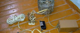
Simple metal detectors from ready-made electrical appliances
- A metal detector can be made from a radio receiver by adding a simple HF transmitter to it:
The search coil is wound from 0.5 mm² wire: 16 turns 12 cm. When a metal object enters the range of action, a receiver tuned to the MW/LW range will change the tone of the sound. - A homemade metal detector made from a cell phone is nothing more than a myth. Upgrading its electrical circuit at home is not feasible, and it is technically impossible to make a standard mobile phone work as a metal detector.
- In fact, there is no need to make a metal detector out of a magnet. You simply bring a powerful neodymium magnet to the place where there is a metal object and physically feel the force of attraction. Of course, this only works with metals that have ferromagnetic properties (iron, steel).
Regardless of the complexity of the design, making a homemade metal detector will require a lot of time and effort from you. Therefore, out of curiosity, such devices are not made. But for professional use, this is an excellent alternative to factory copies.
Metal detector assembly
- Securing the instruments inside the case: a strip of tape is attached to the back of the instruments, then the calculator is placed at the base of the box, the receiver is on the inside of the lid.
- Setting up the receiver: you need to turn on the receiver at maximum volume and select the upper position of the AM range, free from radio broadcasts and interference.
- Adjusting the calculator: when the calculator is turned on, the receiver should respond with a sharp noise, hum or wheezing; if this does not happen, you need to adjust the range.
- Fixing the position: we begin to smoothly close the box until the sound disappears or becomes more uniform and fix the box doors in this position, using a cube of foam plastic, rubber bands, etc.
- The metal detector is ready. If there is a product with electromagnetic radiation nearby, the receiver will sound an alarm.
By combining elements of other radio devices in a simple detector, you can observe the operating principle of metal detectors in action and enjoy your first search expedition.
Note!
Such a detector, assembled at home, can be tested to search for coins or metal construction debris lying in the surface layer of the earth in almost any area, on any open ground.
Video on the topic
Once upon a time, having built several metal detectors of varying degrees of performance with my own hands, I wanted to study how the Arduino circuit works in this direction.
There are several good examples of how to assemble a metal detector with your own hands. However, they usually either require quite a lot of external components to process the analog signal, or the output sensitivity is quite weak.
When we think about pulsed metal detectors, the main topic is how to detect small voltage changes in the signals associated with the search coil. These changes are usually very small. The most obvious approach is to use the ATmega328 analog inputs. But looking at the specs, there are two main problems: they are mostly slow, and the resolution is (in most cases) low.
On the other hand, a microcontroller-based metal detector operates at 16 MHz and has pretty good timing capabilities, namely a resolution of 0.0625 µs when using the clock frequency. So, rather than using an analog input for readout, the simplest way to sense small dynamic voltage changes is to compare the change in voltage drop over time at a fixed reference voltage.
For this purpose, ATmega328 has suitable internal comparator features between D6 and D7. This comparator is capable of triggering an interrupt, allowing events to be processed accurately. Using this along with neatly coded timing routines like millis() and micos(), and using the ATmega328's much higher resolution internal timer, the Arduino is an excellent basis for this kind of metal detector.
So, speaking of the source code - a good start would be to program the internal comparator to "flip" the polarity of the inputs and use the internal counter as fast as possible to change the frequency of the changes.
The final code for Arduino:
Of course, this idea is not entirely new. The bulk of this code may be different. Try searching other sources, such as TPIMD.