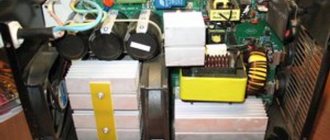
Modern welding work is carried out using special inverters. Previously, conventional transformers, which are characterized by lower efficiency, were used for such metal processing. The schematic diagram of a welding inverter may differ slightly, but they are all characterized by lightness and compactness. Only by taking into account the design features can the welding inverter be repaired and fine-tuned.
Svaris 200 Electrical Circuit Diagram
It is used when welding: Non-ferrous metal.
You can also check whether one of the two overheating sensors on the output rectifier radiator and on the inductor is shorted. In addition, it additionally provides an output winding that provides power to the control circuit.
Some models of modern welding inverters have a programming function, which allows you to accurately and quickly configure their modes when performing a certain type of work. Welding "Svaris 200"
But it won’t be difficult to calculate it.
If this is the case, we move on to another transistor, otherwise we double-check and bite out the faulty transistor, since this makes it easier to prepare a place for installing a working transistor. In each shoulder, two or three powerful field workers stand in parallel.
If there are pulses, you should check their passage to each gate. Article rating: votes: 9, average rating: 4.00 out of 5 Loading
Let's look at a specific example. Don't forget to share with your friends. This is also useful to watch:.
Since the coil itself does not need to increase the frequency, due to this it retains its miniature size. This adds up to DC amps.
Welding inverter repair. Water inside. The welding inverter goes into protection.
Causes of breakdowns of welding inverters
Such devices are operated in conditions that are far from ideal. Dust, humidity, vibrations. Inexperience of operators (welders), savings on consumables (read: the use of low-quality cheap electrodes), unstable input voltage.
It is these factors, and not the complexity of the design, that lead to breakdowns.
Here are the typical causes of malfunctions and malfunctions. The list was compiled based on reviews from service center inspectors.
- Moisture getting inside the case and, accordingly, onto the wiring diagram. When working outdoors, precipitation is often ignored.
- It is possible that splashes of water may occur during the work of adjacent teams - mixing construction mixtures, filling containers, or breaking plumbing networks.
- The inverter housing cannot be sealed. It requires a lot of ventilation holes, so there is no splash protection.
Violation of the cooling mode.
There are several reasons:
Accumulation of large amounts of dust. Ventilation holes become clogged and heat dissipation by cooling radiators is impaired.
Fan failure when hit by a foreign object or bearing jamming due to the same dust.
Failure to comply with the rules of use. You can often see the inverter standing close to the wall (the ventilation holes are closed). Or a rag thrown onto the body.
Violation of operating conditions
The technical specifications always indicate the duration of the load, as a percentage of the cooling time between “approaches”.
In an effort to complete the job as quickly as possible (the pursuit of “workdays”), welders simply drive inverters like horses.
Even with properly organized cooling, continuous operation leads to overheating and breakdown of power elements: key transistors, rectifier diodes.
Contact with metal objects
Chips, fasteners, drops of molten metal during welding into ventilation holes. The result is a short circuit, failure of entire modules.
Any malfunctions of welding inverters arise for the above reasons.
An exception is defective electronic elements or poor-quality installation (misconnection, undersized wires, loose fastening of mechanical contacts).
Signs of malfunction (with the exception of obvious ones, such as smoke from the housing, a burning smell, or extraneous noises inside).
- Unstable arc or intense spattering of welding products (is a malfunction only if the current value is correctly set)
- It is difficult to remove the electrode from the workpiece. The problem occurs frequently; first of all, it is necessary to check all mechanical contacts inside the case for oxidation or loose fasteners
- The inverter is ready for operation (according to the indicators), but welding does not occur. In this case, there is no reason for overheating protection to operate.
When the malfunction is identified, we move on to restoring functionality.
Design features of welding machines and the principle of operation of the inverter - video
Elements of the electrical circuit of welding inverters
The no-load voltage indicator is 62 V. But calculating it will not be difficult.
Video Until recently, all welding work was carried out using powerful step-down transformers, which were large in size and weight. And the presence of an electronic control circuit allows you to smoothly regulate the welding current and provide effective protection against overloads.
The most important functions in an inverter circuit belong to the step-down transformer.
This indicator is achieved by reducing the cost of heating parts and components. The resistance should drop to almost zero and this means that the transistor has opened.
Comment: At the beginning of summer, when I was in the midst of “kalyms”, I had already earned a certain amount of money and decided to spend money on my own personal instrument and not always use my father’s. Low power consumption, approximately 2 times less than conventional welding transformers.
Therefore, its weight is tens of kilograms, which is not entirely convenient.
At the same time, the voltage at the terminals was measured: Everything works fine. Repair of inverter control room RESANTA SAI 220
Interaction of the main components and parts of the inverter
This welding machine circuit consists of the following elements: low-frequency step-down rectifier unit with a capacitor filter; adjustable inverter that converts direct current into high-frequency alternating current; a high-frequency transformer that outputs high-frequency or direct high-power welding current; a phase-shifting inductor that stabilizes the characteristics of the output voltage; a feedback circuit that controls the output parameters and a control unit that changes the welding current and voltage parameters.
As you know, only direct current is supplied to transistors, which is why a rectifier is needed at the input of the device.
The article material is duplicated in the video:.
Also, the feedback signal from the output stage is fed through current transformer T1 to an overload protection circuit made on thyristor Q3 and transistors Q4 and Q5. Two arms, that is, four field workers, are out of order, their terminals are short-circuited.
Welding inverter "MMA 200", device, repair.
The main element of the simplest welding machine is a transformer operating at a frequency of 50 Hz and having a power of several kW.
Therefore, its weight is tens of kilograms, which is not entirely convenient. welding inverters have become widespread . Their main advantages: small dimensions, smooth adjustment of welding current, overload protection. The weight of a welding inverter with a current of up to 250 Amps is only a few kilograms.
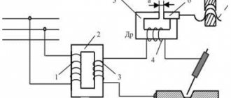
The operating principle of the welding inverter is clear from the block diagram below:
An alternating mains voltage of 220 V is supplied to a transformer-free rectifier and filter (1), which generates a constant voltage of 310 V. This voltage powers a powerful output stage (2). The input of this powerful output stage is supplied with pulses with a frequency of 40-70 kHz from the generator (3). The amplified pulses are supplied to the pulse transformer (4) and then to a powerful rectifier (5) to which the welding terminals are connected. The control and overload protection unit (6) regulates the welding current and protects it.
Since the inverter operates at frequencies of 40-70 kHz and higher, and not at a frequency of 50 Hz, like a conventional welder, the dimensions and weight of its pulse transformer are tens of times smaller than a conventional 50 Hz welding transformer. And the presence of an electronic control circuit allows you to smoothly regulate the welding current and provide effective protection against overloads.
Let's look at a specific example.
The inverter stopped cooking. The fan works, the indicator lights up, but the arc does not appear.
This type of inverter is quite common. This model is called "Gerrard MMA 200 "
We managed to find a diagram of the “MMA 250” inverter, which turned out to be very similar and significantly helped in the repair. Its main difference from the required MMA 200 :
- The output stage has 3 field-effect transistors connected in parallel, while the MMA 200 has 2 each.
- There are 3 output pulse transformers, while the MMA 200 has only 2.
The rest of the scheme is identical.
Briefly about the scheme itself.
At the beginning of the article, a description of the block diagram of a welding inverter is given. From this description it is clear that the welding inverter is a powerful pulsed power supply with an open circuit voltage of about 55 V, which is necessary for the occurrence of a welding arc, as well as an adjustable welding current, in this case, up to 200 A. The pulse generator is made on the U2 microcircuit type SG3525AN, which has two outputs for controlling subsequent amplifiers. The generator U2 itself is controlled through an operational amplifier U1 type CA 3140. This circuit regulates the duty cycle of the generator pulses and thus the output current, which is set by a current control resistor located on the front panel.
From the output of the generator, pulses are sent to a pre-amplifier made of bipolar transistors Q6 - Q9 and field switches Q22 - Q24 operating on transformer T3. This transformer has 4 output windings which, through shapers, supply pulses to 4 arms of the output stage assembled using a bridge circuit. In each shoulder, two or three powerful field workers stand in parallel. In the MMA 200 scheme there are two, in the MMA 250 scheme there are three. In my case, MMA-200 contains two field-effect transistors of type K2837 (2SK2837).
From the output stage, through transformers T5, T6, powerful pulses are supplied to the rectifier. The rectifier consists of two ( MMA 200 ) or three (MMA 250) full-wave rectifier circuits with a midpoint. Their outputs are connected in parallel.
A feedback signal is supplied from the rectifier output through connectors X35 and X26.
Also, the feedback signal from the output stage is fed through current transformer T1 to an overload protection circuit made on thyristor Q3 and transistors Q4 and Q5.
The output stage is powered by a mains voltage rectifier assembled on a VD70 diode bridge, capacitors C77-C79 and generating a voltage of 310 V.
To power low-voltage circuits, a separate switching power supply is used, made on transistors Q25, Q26 and transformer T2. This power supply generates a voltage of +25 V, from which +12 V is additionally generated via U10.
Let's get back to the renovation. After opening the case, a visual inspection revealed a burnt 4.7 uF capacitor at 250 V.
This is one of the capacitors through which the output transformers are connected to the output stage on the field devices.
The capacitor was replaced and the inverter started working. All voltages are normal. A few days later the inverter stopped working again.
Upon detailed inspection, two broken resistors were discovered in the gate circuit of the output transistors. Their nominal value is 6.8 ohms, in fact they are in a break.
All eight output FETs were tested. As mentioned above, they are included two in each arm. Two shoulders, i.e. four field workers are out of order, their terminals are short-circuited. With such a defect, high voltage from the drain circuits enters the gate circuits. Therefore, the input circuits were checked. Faulty elements were also found there. This is a zener diode and a diode in the pulse formation circuit at the inputs of the output transistors.
Schematic diagram of a welding inverter
Modern welding work is carried out using special inverters. Previously, conventional transformers, which are characterized by lower efficiency, were used for such metal processing. The schematic diagram of a welding inverter may differ slightly, but they are all characterized by lightness and compactness. Only by taking into account the design features can the welding inverter be repaired and fine-tuned.
Let's consider the device and principle of operation of the inverter
Inside the inverter, the electrical signal is converted (inverted).
The process is divided into several stages:
- The input power supply generates the primary supply voltage - rectifies alternating current in a standard way
- Then the inverter unit itself comes into play - with the help of a master generator, the direct current again becomes alternating, and high-frequency. It is this quality that makes it possible to reduce the dimensions of the transformer and energy consumption.
- The power unit uses a high-frequency transformer to reduce the voltage to the welding value
- The output AC current is rectified again, since welding with such machines is carried out with direct current.
Despite the integrity of the design - the dense layout of the inverter is clearly visible in the illustration - the electrical circuit consists of several modules.
They can be made on several boards, or assembled together, this does not change the essence. Each module is a separate device (from a circuit design point of view) and has its own input and output parameters.
Important! The relative position of the blocks, the distance between them, and even the laying of connecting wires are carefully calculated at the design stage.
Every little thing matters: mutual interference, self-inductance of radio components and wires, shielding of the signal by the housing... Making changes to the design leads to mismatch of the circuit.
This should be taken into account if you are repairing a welding inverter yourself.
Main modules of the inverter circuit:
- Input rectifier. Its task is to ensure maximum smoothing of the alternating current sinusoid at the input to the inverter. The noise immunity of other modules depends on the quality of its operation.
- Inverter. Actually, this is the heart of the device - with its help, a high-frequency current is generated. Works on the basis of the so-called driver - master chip
- Control module. A separate circuit that is assigned a team task. Thanks to this design element, all other components work in harmony. Power element - transistor switches
- Output rectifier. Part of the circuit that carries the entire load of the welding machine on its elements (power diodes). The module actually operates in short circuit mode - after it only the welding arc
- Elements of protection. At a minimum, there is an overheat sensor and short circuit protection. The last point can be implemented either with a simple fuse or automatic circuit breaker, or with a smart circuit that restores the functionality of the inverter when the causes of the protection operation are eliminated.
In different inverters, these blocks can be placed in any way, but their design is the same. The only differences are in the element base.
Typical arrangement of components in the illustration:
An important design element is active cooling. Each power element (switch transistors, output rectifier diodes) must be located on radiators.
In addition, a fan is installed in the case and air circulation must be ensured. During repairs, check the serviceability of the cooling system and the presence of high-quality thermal contact between radioelements and radiators. Be sure to use fresh thermal paste when replacing parts.
Elements of the electrical circuit of welding inverters
The electrical circuit diagram of an inverter welding machine involves a combination of several elements that are interconnected. The main ones can be called:
- The block responsible for supplying energy to the power section. This element is represented by a combination of several devices that are capable of changing current parameters to the required values. Typically, a capacitive filter and a rectifier are included.
- The device includes a power transformer. The power supply of the welding inverter also includes a 4n90 transistor.
- A separate element is responsible for powering the low-current part of the structure.
- To control the main parameters, a PWM controller is installed. It is represented by a combination of a load current sensor and a transformer.
- A separate block is responsible for protecting the structure from heat. When electrical current passes, some components may become very hot. Therefore, an additional cooling module is installed, represented by a fan and a temperature sensor.
- Control units that allow you to set basic parameters, as well as display elements.
Example of circuit diagram for current 250A
The diode bridge equipment for the welding machine is manufactured and installed taking into account the power of the device and some other points. Each device has its own characteristics, which we will consider in detail below.
Power Electronics
Further, signals from it are sent to:. An operational amplifier produces similar signals, because a direct current generated in the product with high strength values is supplied to the input. In addition, the device receives signals from protection circuits installed in the circuit. Such precautions are necessary to quickly turn off the electrical supply during a critical situation.
This reduces the weight of the welding machine
The inverter is a complex electronic device, but easy to use; it is connected to an electrical circuit with voltage V and welding can be carried out without fear. Such products are in high demand among home craftsmen, because reliable connection of metal structures does not require special welding skills, but only caution and accuracy.
Leave a comment X. Contents 1 Types of current sources 1.
The capacitors installed in the filter, after charging is activated, are capable of delivering a high current that burns, so the inverter is provided with a smooth start. What is the maximum temperature a gas burner can produce? The devices absorb all the power, which reduces heat generation several times. The SVV and K models are recognized as the best. For cooling and protection against overheating, radiators from computers with system units such as Pentium 4 and Athlon are well suited. The case will be needed to compactly accommodate all components.
The width of it should freely accommodate the transformer.
Basic information about inverter devices
There must be jumpers to install the boards. The upper protective casing can be bent from a sheet of 0.5-1 mm, welded or made of several plates. Make ventilation holes in the sheets covering the side walls. The case must have a handle for transportation.
The design should be easy to disassemble. On the front panel, grooves are made for installing the power button, current switches, PWM controller, indicator lights and connectors. Regular or hammer paint in red, blue and orange colors is suitable as a decorative coating. The power supply for a welding inverter can be made from an uninterruptible power supply. All you need is a transformer and a UPS housing with the rest of the filling removed.
After applying voltage B, you need to find a pair with a potential difference of 15 V.
These wires will become the output from the power supply. Here you will also need to install a diode bridge to which consumers will connect. The output voltage will be about 15 V, which will drop under load.
Then the voltage will have to be selected experimentally. A switching power supply allows you to reduce the size and weight of the transformer and save materials. Powerful constant voltage transistors installed in the inverter circuit provide switching from 50 to 80 kHz.
Swaris device diagrams
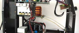
The welding machine Svaris 200 is characterized by ease of use and low cost. Already the Swaris 160 models had high performance characteristics, and the new version was improved. The circuit of the inverter welding machine determines the following operational characteristics:
- The maximum consumption is 5 kW.
- Welding current can vary from 20-200 A.
- The open circuit voltage indicator is 62 V.
- Efficiency rate 85%.
- Recommended electrodes 1.6-5.0.
In general, we can say that the inverter is made according to the classical scheme, which was discussed above.
Diagram of inverter welding machine Mikrosha 200 and 220
Description of the operation of the electrical circuit diagram of inverter welding machines
_ "MIKROSHA"
High image resolution
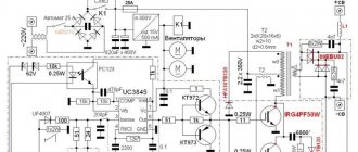
When connected to the network, 2 groups of contacts of switch S1 are closed. In this case, S1.1 connects the supply voltage to the diode bridge of the network rectifier through capacitor C7. At a frequency of 50 Hz, the capacitor has a reactance of several hundred Ohms, which allows for smooth charging of the electrolytic capacitors of the surge protector. Circuit S1.2 turns on the relay power supply circuit. As the capacitors of the +300V circuit are charged, the time delay capacitor C13 is also charged through resistors R44, R45, R50. When the voltage on it reaches the level of +2.5V, the controlled zener diode VD15 opens, relay K1 is triggered, shunting C7 with its contacts.
If there is a malfunction in the high-voltage circuit +300V (transistors or leaky electrical capacitors), VD15 will not open, a voltage of +15V will be present at its cathode and resistor R25, transistor VT1 will open, shunting thermistor R4, which will trigger the comparator at OU2 “OVERHEATING” , EMERGENCY" and blocking the PWM controller.
The +15V power supply is built on TOR258GN. It is a DC-DC converter without galvanic isolation. The sum of the voltages of the zener diodes VD5 and the internal zener diode of the 5.6V microcircuit sets the output voltage (5.6+9.1=14.7V). A protective zener diode VD6 is installed parallel to the internal one. In addition, VD16 protects the power circuit from unforeseen situations and, if the voltage level is exceeded, triggers the current protection of the microcircuit.
PROTECTION COMPARATORS
M/skh IC2 - LM224D: OU2 pins 5,6,7 - pin 5 is supplied with a reference voltage of 2.3V from the divider R5, R6. To inverting input 6 – from divider R3, R4. When the diode radiator heats up, the resistance of the thermistor decreases with increasing temperature. When the voltage value of this divider decreases to the reference level, a high voltage level appears at pin 7, which is supplied through resistor R39 to the OVERHEAT LED and to the analog input of the PIC controller (1). Through R37, the same voltage is supplied to the alarm signal adder -OU3 (pins 8,9,10), from output 10 blocking the operation of the PWM controller through transistor VT6. Transistors VT1, VT2 are also connected to OU2 (pins 5,6,7). The first opens when there is an emergency in the +300V circuit, the second opens by a signal from the PIC controller at low/high supply voltage, which causes the same reaction as heating the thermistor. Comparator OU2(5,6,7) has hysteresis, shifting the temperature threshold of reverse switching through R24, VD7.
OU1 pin 1,2,3 – monitors voltage +15V. Reference - R22, VD8, measured - R20, R21. When you turn on the device, when the power level reaches +13.5V, logic 0 appears on pin 1. When the voltage drops below 11.5V, logic 1 goes to the adder OU3 (5,6,7), prohibiting the supply of power to the PWM controller IC4. Hysteresis is provided by circuit R34, VD17. This protection is necessary for the inverter transistors. When the amplitude of the control pulses decreases to less than 10V, the power transistors may transition to linear mode with large losses and, as a result, fail with the destruction of the crystal.
OU3 pin 5,6,7 – comparator-adder. When at least one signal appears at input 10: a) from temperature sensor No. 1 through R37, b) from the power comparator through R35, c) from temperature sensor No. 2 through R40, it causes a high level voltage to appear at pin 8, which turns off transistor VT6, blocking the power supply to the PWM controller.
The operation of temperature sensor No. 2 on IC 3 is no different from that described earlier No. 1. It is installed on devices with ferrite cores and is set to a response temperature for ferrite overheating of 95-100 C. It is not available on modifications with nanocrystalline cores.
OU4 pin 12,13,14 – error amplifier. The signal from current transformer TV1 is rectified by the diode bridge VD11-VD14, integrated by circuit R23, C12 and supplied through resistor R38 to the inverting input of op-amp 13. Its non-inverting input receives a reference voltage ranging from 0V to +5V from the welding current adjustment resistor R88. The magnitude of the integrated voltage from the CT is of a similar order. The control voltage from pin 14 of IC2 through the divider/integrator R54, R63, C24 is supplied to pin 2 of IC4 of the PWM controller to adjust the current based on the average value. R32, C14 – correction circuit.
IC 4 – SG 2525 AP – push-pull PWM controller. Operating frequency for ferrite cores in models 160, 180 – 60 kHz. For nanocrystalline – 42 kHz. For models 200 and 220 – 42 kHz for any cores. Standard inclusion. Correction circuits. The output signals are amplified by transistor assemblies IC5, IC6 to drive the galvanic isolation transformer (TGR). At the outputs of the TGR - preamplifiers-correctors (drivers) are made according to a circuit with a negative bias in the pause. A signal with an amplitude of +15V in a pulse and -2.7V in a pause is supplied to the gates of power transistors. Negative bias is necessary to protect against random interference and fluctuations from opening the transistor of the opposite side.
The power section is a half-bridge quasi-resonant converter. The switching frequency is higher than the resonant frequency formed by circuit C44, 45, 46, 47, 50, 51 together with the leakage inductance of the transformer, and therefore the shape of the top of the current pulse has a somewhat bell-shaped, rounded appearance and the turn-off current of the transistor does not exceed its turn-on current, not despite the absence of an output choke. The power transformer has a turns ratio of 14/6=2.33, which allows operation at low voltage in the electrical network. For 200-220 modifications with ferrite cores 16/7=2.28, with nanocrystalline ones - 11/5=2.2.
Protection against electrode welding . If there is an arc at the output, the voltage at C49 will always be more than 18V. Optocoupler OS3 is open. The reference voltage from R88 is supplied to the error amplifier IC2 (pin 12). When there is a short circuit at the output, C49 is discharged through R114,115,116 for 0.5-0.8 seconds. Next, the optocoupler closes and the reference voltage drops to the minimum possible value.
The current and afterburner are adjusted using variable resistors R88, R91. When the arc is burning, the output voltage is at least 18V. When arc welding with a coated electrode, the arc at a lower voltage value exists for a short time and tends to go out. The output voltage is integrated by circuit R96, R97, R111, C65. At its standard value, the zener diode VD34 is open, the optocoupler transistor OC2 is also open, shunting the afterburner variable resistor. At output voltage values tending to short circuit, i.e. less than 18V, the zener diode closes, the optocoupler transistor also closes and resistor R91 is connected to the current setting circuit, increasing it by a given amount. The same value is supplied to the second analog input of the processor - pin. 3 display boards. The controller displays changing setpoint current values.
The output power is limited by optocoupler OS1. Caused by the need to reduce output and power consumption during significant, abnormal arc stretching, or when testing equipment using a ballast rheostat at a large load resistance value that does not comply with GOST. Because The devices have a large reserve of power transformer KTP and, accordingly, PWM regulation is possible, they can draw an arc, for example, models 200 and 220 up to 40V at 200A. This causes an overload of the diode bridges, el. capacitors, etc. The divider R87, R89 is selected in such a way that for models 160, 180 the limitation begins when the voltage exceeds 27.5V, for 200, 220 – 30V. When these values are reached, the controlled zener diode VD26 opens, the optocoupler transistor OS1 opens, connecting the divider R66, R67 to the reference voltage. The current decreases.
Measuring mains voltage . Through the divider circuit VD39, C37, R95, R101, R102, through the LC filter L2, C55, the measured voltage is supplied to pin 2 of the indication board and supplied to the first analog input of the PIC18F14K22 controller. The processor periodically displays the voltage value on the indicator, changing the setting current value.
Indication board . The program is flashed and tested before installation on the main board. Both ADCs and one digital input of the processor are used. When an “OVERHEAT” signal is received, or a network voltage value of less than 85 and more than 255 volts, an operation blocking signal is issued from pin 7 of the board, which is supplied through resistor R49 to the base of transistor VT2, causing blocking of the PWM controller through the op-amp circuits. Only calibration based on mains voltage is possible. To do this, it is necessary to close the two-pin connector on the indication board with a “jumper” (jumper) when the device is turned off. Set the mains voltage to 220 volts from LATR. Turn on the device. In this case, the indicator will display a flashing value of 220. The controller measures, averages and remembers this voltage as a reference voltage for some time. For early models - 30 seconds, for later ones - 10 seconds. Then the value of the numbers changes to flashing 100. It is necessary to reduce the supply voltage from the LATR to 100 volts, then remove the “jumper”. After this, the processor will begin to remember the reference level of 100 volts. When the flashing stops, you must turn off the device. After turning it back on, reduce the mains voltage to 85 volts. The lock should work, the “overheating” LED will light up, and on later models the message “VOLTAGE” will appear in a creeping line on the seven-segment digital indicator. WEAK" and flashing numbers 85. Check reverse switching at 90 volts. Similarly, test the device at a voltage of 255V - blocking and the appearance of the inscription “NAPR. OGO-GO", "255". At 250V – unlocking. Next, short-circuit any thermistor with a wire jumper. Blocking and the appearance of the inscription “OVERHEATING 100 C”. The lexical poverty of messages is caused by the inability to display most letters of the Russian alphabet on the digital indicator.
REPAIR
When checking the operation of the control circuit from the power supply, without supplying high voltage, apply +15V to the circuit, soldered, for example, to VD16. First you need to block the protection against low voltage of the electrical network , for which you need to close the resistor R26 with a wire jumper.
When checking models 200, 220, it is necessary to apply +27V voltage by soldering to the soldering points of the fan leads.
Using an oscilloscope, check for the presence of +15, -3V pulses on the gates of the FGH40N60SMD transistors.
ATTENTION ! Do not swap the wires coming from the power switch S1.1, S1.2. One group of contacts switches the mains voltage. The other is the relay supply voltage. If mains voltage enters the relay power circuit, at a minimum you will have to replace VD15, VD16. Early models used a larger switch to switch the full current drawn from the mains. These switches showed their extreme unreliability, and therefore modernization was carried out with changes in the switching circuits.
FAULTS
1. The current is not adjustable. The indicator shows 00. The variable adjustment resistor is damaged as a result of a frontal impact. Replace the 10 kOhm resistor.
In models released from February 2015, the resistors were replaced with others, with additional fastening to the board. The printed circuit board has been changed. The housing cover is extended by 5 mm for additional protection of the regulators.
2. Rotating the FORCAGE knob changes the current value. The current when trying to weld is minimal, welding is impossible. Increased open circuit voltage +95_+115V. The reason is that there is no output + with the VD37 diode. It is carried out through a rivet on the radiator for attaching diodes VD35, VD36. Troubleshooting - solder the wire to the VD37 diode, the other end to the output terminal + . On the latest models, the wire is added as standard, duplicating the contact through the rivet.
Similarly, check the contact of the negative wire to optocouplers OS2, OS3.
3. The power supply attempts to start and goes into protection. Or, when the voltage from the LATR is 80-230 V, it starts normally, but when a mains voltage of 230-250 V is applied, it begins to “hiccup” or starts, and after a while it goes into protection again. The reason is increased current consumption by the control circuit. Having discharged the mains electrolytes, apply voltage from the laboratory power supply, bypassing R26. Check the waveforms on the gates. Check the current consumption from the laboratory power supply. It should not exceed 1 ampere. If there is increased current consumption, unsolder the fan leads. Check the current consumption of each fan individually. Fans with current consumption of 0.2 and 0.3 amperes were installed in the device. Either both are 0.2A, or the rear fan is 0.3A and the front fan is 0.2A. If it is discovered that, as a result of an error and mismatch by the manufacturer, both fans with a current of 0.3A are installed, then it is necessary to solder a resistor with a power of 1-2W with a resistance of 24-27 Ohms in series with the second one. The power and current consumption of the fan will decrease and the TOP258GN m/s will no longer go into protection. It is impossible to change the current protection threshold in this m/s.
4. Failure of power transistors as a result of moisture, dirt, etc. does not require any explanation for experienced craftsmen. Replacement is not difficult. It is necessary to clean the radiator from the varnish along the edge of the transistor mounting area. Check the serviceability of the zener diodes in the drivers and gate resistors. Apply power from the power supply as described earlier and check the oscillograms.
5. Failure of the GBPC3508W diode bridge. The device is silent. All network voltage is applied to capacitor C7. Its reactance allows the device to remain in this position for as long as desired. Ring the bridge. Replace. If overheating occurs due to damage to the rear fan, replace the fan.
6. “OVERHEAT” light is constantly on. Breakdown of capacitor C5 due to interference. Call Replace with 0.1 μfx100V size SMD 1206, or output.
7. The indicator flashes, the displayed numbers are “999” - Controller memory failure. It is necessary to recalibrate according to the mains voltage, as described above in the description of the indication board.
The operating principle of the circuit of 200 and 220 ampere devices is similar. The numbering of components has been retained.
Best regards, Design Engineer
Malik E. V.
Schemes of models MMA-200 and MMA-250
The MMA-200 and MMA-250 models are widely used. These inverters are almost identical, the only difference is the following points:
- The MMA 250 welding inverter circuit provides for the presence of 3 field-type resistors in the output stage. All are connected in parallel. The MMA 200 welding inverter circuit indicates only the presence of two resistors.
- The new version has three pulse transformers, while the old one only has two.
The basic design of both models is almost completely identical.
MMA-200 inverter circuit
Inverter 3200 and 4000 circuits
For manual arc welding, you can use the Inverter 4000 or 3200. Both machines have an almost identical design, which provides the following functions:
- Protection against electrode sticking effect.
- Protecting key components from severe voltage surges.
- Control of basic arc parameters.
- Built-in cooling element with control sensors.
During the manufacture of inverters, IP21 protection was provided. The power of the device is 5.3 kW, powered by a standard power supply network. The detailed diagram of inverter 3200 pro determines the very attractive properties of these models, due to which they have become widespread.
Schemes of other models
As previously noted, almost all inverters operate on a similar principle, and the created circuits may differ insignificantly. All welding machines are divided into several main groups:
- To carry out electric arc welding when using electrodes coated with a special composition, MMA type equipment is used. This scheme is characterized by high efficiency, and the design is light in weight.
- To use refractory electrodes, MMA+TIG welding equipment is used. They can operate in an environment of inert gases.
- On production lines there are units with semi-automatic bar feeding. In this case, work is usually carried out in an environment of inert gases or in special baths.
- For forging or other repairs, spot welding is used.
Repair of welding inverters. Part two.
God bless. Everything returned to its previous place on the forum. Otherwise, in the morning I didn’t understand where I ended up at all. Question to the admin: maybe there is no need to change something? Let it remain as it is. Very inconvenient new version. Well, that's my opinion. As of this morning, there were only 1225 people in the new version of the forum (maybe these are those who tested this version?). But there are much more visitors and forum participants. The forum is very large. Then, about 4 hours later, the problems on the engine were probably fixed, and only now everything returned to its place. To the previous version. A good forum, “yes” some kind of systematization by topics and subtopics is needed. But not so cool. With uv. to the forum administration. Sergey.
[email protected] , Denis.F , There is a fairly reliable relay there. There are three contact pairs. Such relays were even found in 220V voltage stabilizers, which were quite powerful, about 5-7 kW. And they click there much more often than in a welding machine. In the stabilizer, these relays switched a LARGE inductive load on the autotransformer, and this at a time when the load from the stabilizer was NOT disconnected. But here its function is much simpler: turn on once and pass current, these same about 5 kW, until the device turns off. And before that, the capacities on the network, which were just discharged before the device was turned on, i.e. Almost almost a short circuit (ESR) they need to be somehow “smoothly” charged. This is why a resistor or a thermistor first exists, it doesn’t matter. Through it (them), the containers are charged, and then the relay is triggered and supplies the entire 220V network directly. They (resistor or thermistor) are needed there for this. Limit the current surge when the device is turned on. Therefore, I think the problem continues. There can be two of them: a network (network) diode bridge and switches. Probably so. It would be very useful to take a photo of not only the board itself, where everything was burned, but also what is standing next to it.