Reinforced concrete wells
The products consist of two parts - upper and lower. There is a window at the top for installing a hatch. The shape of the wells is made round, square or in the form of a prism.
Concrete is prepared with fine aggregates to ensure water resistance and water resistance. The product may contain a hydrophobic coating to protect against groundwater. The structure is reinforced with a frame made of steel mesh or reinforcement, which is assembled by spot welding.
The container is equipped with pipes for cable entry. They are connected to cable sleeves using compression couplings, rubber cuffs or extrusion welding.
Plastic cable manholes
The benefits of plastic are driving the proliferation of sewer pits for electrical and telecommunications networks. Depending on the design, each type has its own marking.
- KKT-1 – well for telephone communications. Manufactured primarily for the private sector. The strength of the body is ensured by stiffening ribs.
- CODE – well for quick access. It is intended for installation of optical highways. The well contains couplings. The polyethylene structure contains distribution pipes on all walls.
- KKTM is a small-sized well for low-pair communications. Used as a container or as a manhole.
The low weight of plastic structures greatly simplifies their installation. A foundation slab is installed at the bottom, to which the container is attached with a cable or anchor. Installation is done manually. Backfilling is done with a mixture of sand and cement.
Regulatory documentation
The main document regulating the requirements for the design, manufacture and operation of cable wells is TU 45.1418-89 Cable duct inspection devices for KKS communications. The service life of these technical specifications has been extended without indicating the expiration date. It is also possible to use other approved and current specifications, including TU-5855-001-92718053-2012.
Terminology and basic concepts that must be used when creating regulatory documentation are contained in GOST R 50889-96. According to this GOST, a communication cable well should be called a “cable duct well”.
The procedure for organizing networks of cable pipelines, the design of cable wells, their placement and selection of their type, the introduction of pipelines into cable wells is regulated by the “Guidelines for the construction of linear structures of local communication networks” (Guidelines for SLSMSS) of the Ministry of Information Technologies and Communications of the Russian Federation.
In the manufacture of KKS, regulatory documentation on components for manholes is also used:
- GOST 8591 76 Hatches for cable wells of telephone sewerage. Technical conditions.
- GOST 8020 90 Concrete and reinforced concrete structures for wells of sewerage, water supply and gas networks. Technical conditions.
Which well is better
While reinforced concrete wells with asbestos-cement pipes can work reliably and for a long time in harsh conditions, plastic wells do not always withstand them. The main reasons are unreliable pipe connections.
The SKTB-TOMASS company tried to introduce innovative ideas for the introduction of plastic wells in 2005. She developed the design of the PKK-2U-M1 brand made of polyethylene, documentation and mastered its own production. The device contains an internal steel frame and must be closed from above with a concrete slab with a hatch resting on the ground. Only in this case can the structure be a substitute for concrete.
Modern manufacturers of plastic wells know practically nothing about this design and more than ten years of experience in its operation. In all the lines of manufactured models it is impossible to find a single design that continues the work of the PKK well. Outwardly they seem convenient, but in fact they sell barrels, septic tanks and tanks, etc. containers made of plastic. The instructions say nothing about their flammability, the effect of hot asphalt, or the possibility of repair when the neck is demolished by a bulldozer. We are not impressed by the modest size of plastic containers, which cannot compete with concrete products for multi-pair sewers. The lightness of the structure has become a disadvantage since it requires support and anchor plates and specially fitted molds. All this increases the cost of the well.
Plastic consoles and brackets glued to the walls are not nearly as reliable as elements of reinforced concrete wells made of metal. It is impossible to install couplings in many plastic wells, and if they do manage to be “stuffed”, the bending radii of the cables become completely unacceptable.
When installing a lightweight polymer container, for greater reliability, you have to mount a sarcophagus made of a concrete slab with a cast-iron hatch on top, and install another one below as an anchor.
Main types of cable wells
Regarding the variety: today a fairly wide variety of cable wells are being produced.
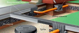
Construction of a cable well
Here is an example of the most popular ones:
- KKT-1 and KKT-2 are used as universal inspection well systems. They are used when laying ordinary low-pair communications in residential buildings (KKT-1) and to place passive equipment (KKT-2).
- CODE – used when laying fiber optic networks. Optical couplers are installed in the chamber, and they are also used as a place to store spare optical fiber.
- KKTM – designed for low-pair telephone networks. It can be manufactured with a body in the form of a cylinder (KKTM-1), and with a downward extension, which is used for installing various devices (KKTM-2).
- KKS are concrete wells for cable communications, the elements of which are highly durable and reliable. Can be used in residential areas and industrial areas.
In addition, a separate role in this list is given to cable wells intended for power cables. Their design creates better electrical protection thanks to the use of the latest insulation materials.
Advantages of plastic compared to concrete
Despite the large selection, plastic products are now slowly and widely replacing concrete ones.
Plastic cable manhole
There are several reasons for this:
- They have a lower specific gravity with the same mechanical properties.
- They have a highly sealed design.
- The materials used are characterized by chemical inertness, since they are not destroyed by the action of soil solution, they are also durable and environmentally friendly.
Attention: There is a difference between plastic and plastic. The instructions must be read in full before purchasing. After all, it may be plastic and electrical, or something else. There are many types of them. Also pay attention to its reaction to humidity. After all, they are also made in rooms with high humidity. And this is your health.
Please note that their low level of porosity makes them resistant to low temperatures for fifty years. The service life is not affected by the amount of freezing, which plays an important role for Russia, where the climate may not be stable.
- The material is plastic, which makes it possible to manufacture them of almost any size, and also allows for the implementation of various engineering ideas (technological holes, coupling fasteners, etc.).
- The cost of plastic wells is also quite reasonable.
Features of laying cable ducts
The laying of cable channels is carried out according to certain rules.
- The pipes are buried to a depth of 40-200 cm. Plastic pipes are laid at the minimum depth, and cement-based pipes are laid the deepest. Any pipelines that require the greatest depth are laid under tram tracks. At a medium depth, pipes are installed under roads, at a minimum depth - under pedestrian areas.
- The channels are made with a slope of 4 mm/m, so that the water that gets there does not linger, but flows down.
- Pipes between wells are always located in a straight line. The permissible displacement is no more than 10 mm/m.
- In the basements of houses or in large collectors, it is advisable to lay cables not in pipes, but on consoles.
- Wires with the lowest voltage are laid to the shallowest depth.
- The optimal pipe diameter for the cable is considered to be 100 mm.
- It is not allowed to lay telephone and electrical wires in a common pipe.
- The volume of the well is selected depending on the location and purpose.
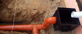
Construction of a manhole
Cable wells are no different in appearance from waste wells, which are containers with a bottom and a hatch on top. The hatch can be with or without a neck. For pipes with cables, holes are provided during manufacture or holes are made in the walls of the housing. Most designs contain double hatches, where the inner one is equipped with a special secret lock.
The type of well depends on the position in the network:
- pass-through - installed on straight sections or in other places where deviations reach 30°;
- station - located next to buildings;
- rotary – placed at the point where the network turns;
- dividing – in places where a line branches into several lines.
The dimensions of the well must make it possible to work with the cable and install equipment. The material is often plastic with stiffeners.
Cable duct installation
Cables are laid by professionals, since installation errors result in problems in the operation of electrical networks and communication lines. The work includes a sequence of actions.
- Drawing up a design drawing indicating all other communications located next to or at intersections with the cable installation site.
- Terrain marking.
- Making a pit for a well with dimensions 40 cm wider than the dimensions of the container. A sand cushion is made at the bottom, which should be thoroughly compacted. In flooded areas, the bottom of the pit is cemented.
- In accordance with the markings, trenches are dug with a slope for cable pipes. When other communications are located nearby, the work is done manually. The crumbling soil is secured with wooden sheets with spacers. The bottom is covered with sand or filled with a layer of concrete.
- A well is installed at the bottom of the pit at a level. The holes in the walls must correspond to the places where the pipes are laid for the cables. The container is attached to a concrete base. It may be provided with a loading chamber, which is filled with cement.
- Pipes are laid in the trenches at a distance of 20-25 cm. The free space is filled with soil. The top layer of pipes is separated from the bottom layer with a thickness of 25 cm. The soil is compacted around the pipes with a wooden shovel.
- The joints between the well and the pipes are sealed. The final backfilling of the well is done with a mixture of soil and sand, with compaction every 0.2 m.
- Wires are pulled into cable channels. Their tension should be controlled so that it does not exceed the norm. Particular attention is paid to laying the fiber optic cable.
How is installation done?
Installation of a cable well takes place in several stages:
- First, a pit is prepared. It should exceed the dimensions of the well by approximately 200 mm.
- Next, a concrete cushion is produced. Its dimensions depend on the dimensions of the cable well. If the groundwater level is higher than the bottom of the well, the bulk soil should be thoroughly compacted. Finally, an anchor is built from concrete, which will prevent the well from floating. The anchor is made using formwork with a round or rectangular cross-section. If a well is installed where transport passes, a 200-mm reinforced slab is poured, which will make it possible to evenly distribute the load.
- The installation of the well itself is carried out using special equipment, but the work can also be done manually. The structure is attached to anchor bolts and cables.
- Carrying out backfilling. The backfill is a mixture made of sand and cement in a ratio of 1/5. It should be carefully compacted every 20 cm.
Connection to the conduit system can be made using various methods:
- using a sliding coupling with sealing rings;
- using a compression coupling;
- using a sliding coupling with sealing rings.
Communication wells are actively used in buildings of various types. They reliably protect cables from damage and last a long time. Wells of this type are made from various materials, but plastic is most often used. Devices must be built in accordance with a number of technical standards and rules. If you use high-quality materials, do not violate technology and choose the right location, the communication well will serve your home for a long period of time.