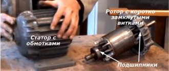
One phase instead of three
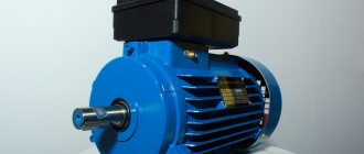
The most common option is a three-phase asynchronous motor.
Three windings are laid in the slots of the stationary stator with a shift of 120 electrical degrees. To start, it is necessary to pass a three-phase current through them, which, passing through each winding at different times, creates a torque that spins the rotor. This does not happen when connecting a single-phase network. Therefore, additional elements are needed here, such as a phase-shifting capacitor. This is the easiest way. This will not affect the rotation speed of the rotor, but the power of such an electric machine will drop. Depending on the load on the shaft, capacitor capacity, connection diagram, losses are 30–50%.
It is worth immediately noting that not all brands of devices operate on a single-phase circuit. But still, the majority allows such manipulations to be carried out on themselves. You should always pay attention to the attached signs. There are all the characteristics, looking at which you can see what model it is and where it will work.
From the first picture (A) we can conclude that this motor is designed for two voltages - 220 and 380 V. The windings are switched on - delta and star. You can run it from a regular home network (there is the appropriate voltage), and preferably with a triangle.
The second (B) shows: the electric machine is designed for 380 V, star switched on. Theoretically, it is possible to switch to a lower voltage, but to do this you need to disassemble the housing, look for the connection of the windings and switch them to a triangle. You can, of course, not switch anything by simply installing a capacitor. However, the power losses will be colossal.
If the sign says: Δ/Ỵ 127/220, then such a device can only be connected to a 220 V network with a star, otherwise it will burn out!
Connecting a 3-phase 220 motor without capacitors
As a rule, circuits without capacitors are used to start low-power three-phase motors in a single-phase network - from 0.5 to 2.2 kilowatts. Start-up time is spent approximately the same as when operating in three-phase mode.
These circuits use triacs controlled by pulses of different polarities. There are also symmetrical dinistors that supply control signals to the flow of all half-cycles present in the supply voltage.
There are two options for connecting and starting. The first option is used for electric motors with a speed of less than 1500 per minute. The windings are connected in a triangle. A special chain is used as a phase-shifting device. By changing the resistance, a voltage is generated across the capacitor, shifted by a certain angle relative to the main voltage. When the capacitor reaches the voltage level required for switching, the dinistor and triac are triggered, causing activation of the power bidirectional switch.
The second option is used when starting engines whose rotation speed is 3000 rpm. This category also includes devices installed on mechanisms that require a large moment of resistance during startup. In this case, it is necessary to provide a large starting torque. To this end, changes were made to the previous circuit, and the capacitors required for the phase shift were replaced by two electronic switches. The first switch is connected in series with the phase winding, leading to an inductive shift of the current in it. The connection of the second switch is parallel to the phase winding, which contributes to the formation of a leading capacitive current shift in it.
This connection diagram takes into account the motor windings, which are displaced in space by 120 0 C. When setting, the optimal angle of current shift in the phase windings is determined, ensuring reliable starting of the device. When performing this action, it is quite possible to do without any special equipment.
Connecting a phase-shifting capacitor
The optimal option for connecting a three-phase machine to operate from 220 volts is a triangle. So the losses will be about 30%. Two ends in the bourne go directly to the network, and a capacitor is connected between the third end and either of these two.
Such a start is possible if there is no serious load: for example, when a fan is connected. If there is a load, the rotor will either not spin at all, or the startup will take a very long time. In this case, it is worth adding a starting capacitor.
In this case, it would be good to use a switch in which one contact would close and be fixed until it is turned off, and the other would turn off when it is released. This way you can connect the starting capacitor to work for a short time. The direction of rotation is changed by switching the capacitor in the circuit to another phase.
In practice it might look like this:
The circuit for starting a three-phase motor in a single-phase circuit with a star is also simple. The losses will be greater, but sometimes there is simply no other choice.
Conversion of the electric motor from 380 to 220 Volts
If you have a three-phase electric motor, you know it doesn't come cheap. Therefore, if you need to use a single-phase motor, the thought of buying new equipment will only come to you when you do not know how to make an electric motor at home. We will tell you how to convert an electric motor from 380 to 220 Volts with your own hands.
Capacitor calculation
It is a completely natural question about what parameters a capacitor should be used to start and operate such a device. It all depends on whether the windings on a three-phase machine are star or delta connected.
- For a star there is the following calculation: Cр = 2800•I/U.
- Triangle: Cр = 4800•I/U.
Cp is the capacity of the working capacitor in microfarads, I is the current in amperes, U is the network voltage in volts.
- The current can be calculated this way: I = P/(1.73•U•n•cos f).
P is the power of the asynchronous machine, written on its label, n is its efficiency. It is indicated there, and cos f is written next to it.
There is also a simplified calculation option. It looks like this: C = 70•Pn, where Pn is the rated power, kW (on the tag). From this formula we can conclude that for every 100 W there should be about 7 µF of capacitance.
If the capacitor capacity is too high, the windings will get very hot; if the capacitor is too low, the rotor will be difficult to spin. Therefore, the ideal option is when, after all the calculations, a kind of “adjustment” is made: the current is measured using clamps and additional capacitors are added or removed.
If you need a starting capacitor, then you need to select it so that the total capacitance (Cp + Sp) is 2-3 times higher than the working capacitance (Cp).
Connecting a 380V to 220V electric motor via a capacitor
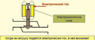
For a normal connection, you should know the principle of operation of a three-phase motor. When connected to a three-phase network, current begins to flow alternately through its windings at different times. That is, in a certain period of time, the current passes through the poles of each phase, also creating a rotational magnetic field in turn. It exerts an influence on the rotor winding, causing rotation by pushing in different planes at certain times.
When such a motor is connected to a single-phase network, only one winding will participate in the creation of rotating torque and the impact on the rotor in this case occurs only in one plane. This force is completely insufficient to shift and rotate the rotor. Therefore, in order to shift the phase of the pole current, it is necessary to use phase-shifting capacitors. The normal operation of a three-phase electric motor largely depends on the correct choice of capacitor.
Calculation of a capacitor for a three-phase motor in a single-phase network:
- With an electric motor power of no more than 1.5 kW, one operating capacitor will be sufficient in the circuit.
- If the engine power is over 1.5 kW or it experiences heavy loads during startup, in this case two capacitors are installed at once - a working one and a starting one. They are connected in parallel, and the starting capacitor is needed only for starting, after which it is automatically turned off.
- The operation of the circuit is controlled by the START button and the power off toggle switch. To start the engine, press the start button and hold it until it is fully turned on.
If it is necessary to ensure rotation in different directions, an additional toggle switch is installed that switches the direction of rotation of the rotor. The first main output of the toggle switch is connected to the capacitor, the second to the neutral, and the third to the phase wire. If such a circuit causes a drop in power or a weak increase in speed, in this case it may be necessary to install an additional starting capacitor.
Gradual acceleration
How can you smoothly start an asynchronous motor in a single-phase network? It is worth mentioning right away that for home use this will be expensive. The circuit itself is very complex and there is no point in trying to assemble it yourself. There are special soft starters that are successfully used for this purpose. Their essence lies in the fact that during the first seconds of switching on, the supply voltage is supplied too low, as a result of which the starting torque is reduced.
But since the rotation speed of rotor-type devices depends on the frequency of the supply voltage, and not on its magnitude, this option is suitable only when there is no significant load on the shaft: pumps, fans. If there is a load, then it is best to use a frequency converter. It will also provide a smooth start-up along with many other great features. True, it costs more. The conclusion follows from this: such devices are more suitable for use in production, even small ones. It's expensive for a home.
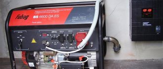
As you can see, this frequency generator can be powered with either three-phase or single-phase voltage.
Technology for generating torque from a single-phase network
In this situation we have only one voltage. You need to make three different currents from it, ideally shifted by 120 degrees, which is not easy.
To do this, they use reactance, knowing that in a capacitor the current is ahead of the voltage phase, and in an inductance it lags behind by 90 degrees. The lack of angle deviation is 25%, which already affects energy losses.
A three-phase motor in a single-phase network operates inefficiently: power losses can exceed up to 50%, and in some circuits even higher.
However, often this drawback is not critical. It suits most users.
Single phase
In order to connect a single-phase asynchronous motor, two buttons are enough: one with a latch, the other without it. Standard circuit: two windings connected in series (although there may be variations depending on the model). The one with greater resistance is the starting one, the other is the working one.
Each model of electric machine has its own characteristics, which means the connection options may vary. Some use two capacitors to start, others use one.
Therefore, you need to start by finding out the model and its technical characteristics.
As you can see, starting short-circuited electric machines is possible in different ways. Connection is possible both at home and at work, which is what made them so popular. And, by and large, nothing better has been invented in more than a hundred years.
How to change the direction of rotation
If you need to change the direction only once, then this can be done at the rework stage. To do this, it is enough to swap any two stator windings. The same goal is achieved by transferring a branch of capacitors from zero to phase, or vice versa. But if you need to frequently reverse a three-phase converted motor, a switch is needed. By assembling the electric motor according to the diagram below, you will free yourself from changing the windings every time you need to set the direction of rotation of the shaft in the opposite direction.
There is nothing difficult about converting a three-phase electric motor to a single-phase network with your own hands. The greatest difficulty will be only the calculation of the capacitance of the working capacitor and the experimental selection of the capacitance from the calculated range for the starting accumulator. But this becomes easy if you haven’t lost your technical passport and have a calculator at hand.
More on the topic:
— Connection diagrams for asynchronous and synchronous single-phase motors— Connection diagrams for an electric motor through capacitors— Reversible diagram for connecting an electric motor
— Do-it-yourself soft start of an electric motor — What is the difference between asynchronous and synchronous motors — Do-it-yourself reversible connection of a single-phase asynchronous motor
— How to check an electric motor— Electric motor repair
Connecting a 3-phase motor at 220 without loss of power
The simplest and most effective way is to connect a three-phase motor to a single-phase network by connecting a third contact connected to a phase-shifting capacitor.
The highest output power that can be obtained in domestic conditions is up to 70% of the rated one. Such results are obtained when using the “triangle” scheme. Two contacts in the distribution box are directly connected to the wires of the single-phase network. The connection of the third contact is made through a working capacitor with any of the first two contacts or wires of the network.
In the absence of loads, a three-phase motor can be started using only a run capacitor. However, if there is even a small load, the speed will increase very slowly, or the engine will not start at all. In this case, an additional connection of a starting capacitor will be required. It turns on for literally 2-3 seconds so that the engine speed can reach 70% of the nominal speed. After this, the capacitor is immediately turned off and discharged.
Thus, when deciding how to connect a three-phase motor to a 220 volt network, all factors must be taken into account. Particular attention should be paid to capacitors, since the operation of the entire system depends on their action.
The theoretical material presented in the first part of the topic, devoted to the single-phase connection of a three-phase electric motor, is intended so that the home master can consciously transfer industrial devices of a 380-volt network to household electrical wiring of 220.
We recommend that you carefully read this article here.
Thanks to it, you will not just mechanically repeat our recommendations, but will implement them consciously.
Optimal diagrams for connecting a three-phase motor to a single-phase household network
Among the many ways to connect an electric motor in practice, only two are widely used, called briefly:
The name is given by the method of connecting windings in an electrical circuit inside the stator. Both methods differ in that they apply a different voltage to each phase of the motor.
In a star circuit, linear voltage is applied directly to two windings connected in series. Their electrical resistance adds up, providing greater resistance to the passing current.
Read also: What is the temperature in the fire?
In a triangle, linear voltage is applied to each winding individually and therefore has less resistance. Currents are created higher in amplitude.
Let us pay attention to these two differences and draw practical conclusions for their use:
- the star circuit has reduced currents in the windings, allows you to operate the electric motor for a long time with minimal loads, and provide small torques on the shaft;
- The higher currents produced by the delta circuit provide better power output, allowing the motor to be used under extreme loads, so it requires reliable cooling for long-term operation.
These two differences are explained in detail in the picture. Look at her carefully. For clarity, red arrows specifically mark the incoming voltages from the line (linear) and those applied to the windings (phase). For a triangle circuit they are the same, but for a star they are reduced by connecting two windings through the neutral.
These methods should be analyzed in relation to the operating conditions of your future mechanism at the design stage, before the start of its creation. Otherwise, the motor of the star circuit may not be able to cope with the connected loads and will stop, while the motor of the delta circuit may overheat and eventually burn out. The motor current load can be determined by selecting the connection diagram.