The idea of replacing labor-intensive forging with rolled metal arose at the beginning of the 16th century, and at the same time the first rolling mills appeared, giving metal its shape by compressing it between rotating rolls. The power of the water wheels that drove the rolling mills was only enough to process soft metals - tin, lead, copper. The advent of the steam engine made it possible to roll hard steel. The development of railways increased the demand for rolled products - steel rails. The first mill to roll steel rails opened in 1828 in Bedlington, England.
1. Gold wire jewelry. Northern Europe. II - I millennium BC e. 2. Russian filigree: gold bracelet of the 13th century. and a silver button from the 16th century.
Jewelry thought
Wire jewelry in the 2nd millennium BC. e. confirm that even then the ancient craftsmen, in addition to forging - the simplest method of processing metals by pressure - used drawing - pulling cast rods of soft metals through the narrow holes of drawing boards, to thin them and turn them into wire .
In Byzantium and Russia , laying out wire patterns - filigree - was especially popular. Wire for filigree was often flattened, and perhaps as early as the 15th century. , flattening rollers began to be used . Later, having made streams in the rollers - notches of different widths and shapes, they found a new way of drawing wire: the stream compressed the workpiece, giving it the desired thickness and profile . Jewelry flattening rollers could become the prototype of a sheet rolling mill (for rolling flat metal sheets), and wire drawing rollers suggested the idea of a forming rolling mill (for rolling beams of different profiles).
Leonardo da Vinci's rolling mill: drawing from 1495 and modern layout. The handle (1) rotated the upper roller (2), and through a gear train (3) consisting of several gears (to facilitate rotation), movement was also transmitted to the lower roller (4). A cast tin plate was rolled between the rollers; the rollers compressed and thinned it, turning it into a sheet.
rolling mill,
a machine for pressure processing of metal and other materials between rotating rolls, i.e., for carrying out the
rolling
, in a broader sense - an automatic system or line of machines (unit) that performs not only rolling, but also auxiliary operations: transportation of the original workpiece from warehouse to the heating furnaces and to the mill rolls, transfer of rolled material from one caliber to another, turning, transportation of metal after rolling, cutting into parts, marking or branding, straightening, packaging, transfer to the finished product warehouse, etc.
Historical reference.
Time and place of appearance of the first P. s. unknown. It is indisputable that before rolling iron, they used the rolling of non-ferrous metals - lead, tin, copper, coin alloys, etc. The earliest document (drawing with description) characterizing a device for rolling tin was left by Leonardo da Vinci (1495). Around the end of the 17th century. drive P. s. was manual, in the 18th century. - water. Industrial rolling of iron began around the 18th century. In Russia, it developed especially widely in the Urals. P.S. were used for the production of roofing iron, flattening the billet into a strip or sheet, dividing the forged strip along its length into smaller profiles of square or rectangular cross-section (the so-called “carving” mills).
At the end of the 18th century. for drive P. s. steam engines began to be used; rolling becomes one of the three main links in the production cycle of metallurgical plants, gradually replacing the less productive forging method.
The industrial use of P. s. dates back to this period.
with calibrated rollers, designed in 1783 by G. Court
(Great Britain);
P.S. are gradually differentiated into crimp, sheet and varietal. In the 30-40s. 19th century Due to the rapid development of railways in different countries, rails are beginning to be rolled. In 1856–57, the first rolling mill, intended for rolling large beams, was installed in Saarland (Germany). The development of designs and specialization of these mills led to the appearance in the USA at the end of the 19th century. bloomings
and
slabs.
In 1867, G. Bedson (Great Britain) built a continuous wire mill.
In 1885, the brothers M. and R. Mannesmann
(Germany) invented a method for screw rolling of seamless pipes in P. s.
with obliquely located rollers. In 1886, W. Edenborn and C. Morgan (USA) used a high-speed wire winder with
axial feed. The first flying shears (designed by W. Edwards) were installed in 1892 in the USA. In 1897 for the drive of P. s. An electric motor (Germany) was successfully used. In 1906, a P. s. was launched in the city of Třinec (now Czechoslovakia). with a reversible electric motor. The principle of continuous hot rolling of sheets found practical application in 1892 in Teplice (now Czechoslovakia), where a semi-continuous mill was installed. The first continuous broad strip (sheet) mill was built in 1923 in the USA. The beginning of cold rolling of sheets dates back to the 80s. 19th century; Cold rolling of pipes was developed in 1930 in the USA.
In the USSR, the first achievement of machine tool construction was the construction by the Izhora plant of two blooming plants, which were put into operation in 1933 at the Makeyevka and Dneprodzerzhinsk metallurgical plants. In the 1940s-60s. The All-Union Research and Design Institute of Metallurgical Mechanical Engineering (VNIIMETMASH) has created a number of P. s. for new technological processes that ensure the production by rolling of many products that were previously produced by other, less efficient methods (thin-walled risk-free pipes, sheets of variable thickness along the length, profiles of circular periodic section, balls, bushings, coarse-pitch screws, ribbed tubes, etc.) . In 1959–62, VNIIMETMASH and the Elektrostal Heavy Engineering Plant created fundamentally new pipe mills with endless reduction
pipes (both furnace welding and radio frequency), as well as mills for continuous rolling of seamless pipes (mill 30-102) with productivity an order of magnitude higher than the existing ones (about 550 thousand tons
/
year). During these same years, the first mills for rolling cylindrical and bevel wheels, developed by VNIIMETMASH, the Scientific Research Institute of the Automotive Industry and the Gorky Automobile Plant, were launched.
In the 60s in the USSR, USA, Germany and Italy, the creation of casting and rolling units has begun, which combine continuous casting
and rolling in a single continuous flow.
Such units have already been widely used for the production of wire rod
from aluminum and copper alloys, sheets from aluminum alloys and steel billets.
Classification and design of rolling mills.
The main feature that determines the design of a P. system is its purpose, depending on the range of products or the technological process being performed.
According to the product range of P. s. They are divided into billets, including mills for rolling slabs
and
blooms
, sheet and strip, sections, including beam and wire, pipe rolling and parts rolling (tires, wheels, axles, etc.). According to the technological process of P. s. are divided into the following groups: casting and rolling (units), crimping (for squeezing ingots), including slabs and bloomings, reversible single-stand, tandem, multi-stand, continuous, cold rolling. The size of a mill intended for rolling sheets or strips is characterized by the length of the roll barrel; for billets or long metal, by the diameter of the rolls; and for a pipe rolling mill, by the outer diameter of the rolled pipes.
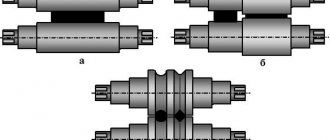
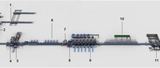
The equipment used for deforming metal between rotating rolls is called the main equipment, and for performing other operations it is called auxiliary. The main equipment consists of one or more main lines, each of which contains 3 types of devices ( Fig. 1
): working stands (one or more) - these include rolling rolls with bearings, frames, installation mechanisms, plates, wiring;
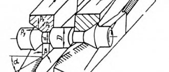
electric motors for rotating rollers; transmission devices from electric motors to rolling rolls, consisting mostly of a gear cage, spindles and couplings. A gearbox is often installed between the gear cage and the electric motor. If each roll has its own electric motor, the transmission devices consist only of spindles. The most widespread are mills with horizontal rolls: two-roll (duo), three-roll (trio), four-roll (quarto) and multi-roll ( Fig. 2
).
To compress metal along the side surfaces, stands with vertical rolls, called edgers, are used.
Mills in which vertical rolls are located near horizontal rolls are called universal. They are used for rolling wide strips and I-beams with wide flanges. In screw rolling mills, the rolls are located in the working stand obliquely - at a feed angle. Such mills are used for rolling pipes, axles, balls, etc.
The number and location of working stands of P. s. determined by its purpose, the required number of passes of metal between the rolls to obtain a given profile and the specified productivity. On this basis, P. s. are divided into 8 types ( Fig. 3
).
Single-stand mills include most blooming mills, slab mills, ball rolling mills, and cold rolling mills for sheets, strips and pipes. In cases where it is not possible to place the required number of calibers in one working stand (see Calibration
of rolling rolls) or when high productivity is required, mills with several working stands are used.
The most advanced multi-stand mill is a continuous one, in which metal is simultaneously rolled in several stands ( Fig. 4
). Continuous mills are used for hot rolling of billets, strips, sections of metal, wire, pipes, as well as for cold rolling of sheets, tin, strip and other profiles.
Rolling speeds are very different and depend mainly on the required productivity of the rolling mill, the range of products being rolled, and the technological process. For crimping, billet, plate, and large-section mills, the rolling speed is about 2-8 m
/
sec.
The highest speeds are typical for continuous mills: when rolling long metal, 10-20
m/sec
;
strip 25-35 m
/
sec
;
wire 50-70 m
/
sec
;
during cold rolling of sheet metal 40 m/sec.
Data on the productivity, drive power, and weight of equipment of some rolling mills that are most widely used in the USSR for the production of hot-rolled steel are given in the table.
Brief characteristics of the main hot rolling mills
| Mill type | Rolled product range | Productivity, thousand tons/year | Total power of main drives, kW | Equipment weight, t |
| Blooming single-cage duo 1000—1300 | Blooms from 200´200 mm up to 370´370 | Up to 6,000 | Up to 13 600 | Up to 5,500 |
| Leaf wideband continuous 2000 | Strips thickness 1.2-16 mm, width up to 1850 | 6 000 | 120 000 | 40 000 |
| Thick plate double 3600 | Sheets and slabs thicker 5—200 mm, width up to 3200 | 1 750 | 21000 | 60 000 |
| Continuous billet 900/700/500 | Blanks with a cross section from 80´80 mm up to 200´200 | 5 550 | 30 400 | 10 500 |
| Beam-rail stepped trio 800 | Rails, beams from No. 24 to No. 60, channels from No. 20 to No. 40, etc. | 1 700 | 9 800 | 22 000 |
| Large Grade Step Trio 650 | Round steel with a diameter of 70—220 mm, b. llki from No. 16 to No. 30, etc. | 750 | 8 700 | 6 500 |
| Large grade semi-continuous 600 | Round steel with a diameter of 50—120 mm, beams from No. 10 to No. 20, etc. | 1 600 | 34 400 | 18 000 |
| Mid-grade semi-continuous 350 | Round steel with a diameter of 20–75 mm, beams and channels up to No. 10, etc. | 1000 | 16 000 | 7200 |
| Small grade continuous 250 | Round steel with a diameter of 8—30 mm, corner profile from 20´20 | 800 | 16 000 | 6 600 |
| Narrowband continuous 300 | Strip thickness 2-8 mm, width 120–460 | More than 1000 | 15 200 | 2 700 |
| Wire continuous 150 | Wire rod with a diameter of 5.5—12.5 mm | 900 | — | — |
| Automatic pipe rolling | Seamless pipes with a diameter of 140–426 mm | 50—70 t/h | 12 000 | 8000—12 000 |
| Pipe rolling continuous 110 | Seamless pipes with a diameter of 50-110 mm | 50—80 t/h | 12 000 | 3 500—5 000 |
Billet mills are built in two types depending on the source material - ingots cast in molds or continuously cast billets. In the first case, the billet mill is also a crimping mill. Typical representatives of such mills are slab mills, when flat workpieces of large sections (slabs) are required, and blooming with a continuous billet mill installed behind it, if it is necessary to roll the billet for section or pipe rolling mills. Behind the last stand of these mills there are flying shears for cutting the workpiece into pieces of the required length, or saws and racks for cutting, cooling and inspecting the workpiece. When using continuous casting, the billet mill is installed next to the continuous casting machine in order to utilize the heat of the hot metal. Some billet mills are designed so that the cast billet flows from the mold into the rolls of a continuous mill without cutting, i.e. in this case, a billet of infinite length is rolled and divided into pieces of the required length by flying shears or saws as it exits the mill rolls.
Sheet and strip hot rolling mills are designed to produce slabs with a thickness of 50–350 mm,
sheets with a thickness of 3-50
mm
and strips (wound into rolls) with a thickness of 1.2-20
mm.
Plate mills usually consist of 1-2 duo and quarto stands with a roll barrel length of 3500-5500
mm
(see
Fig. 1
), sometimes with additional stands installed in front of them, which have vertical rolls for compressing the side edges.
For strip rolling, the most widely used are wide-strip continuous or semi-continuous mills, consisting of 10-15 quarto stands with a roll barrel length of 1500-2500 mm
and several stands with vertical rolls.
All rolled material is wound into rolls of 15-50 tons.
These mills are much more productive than thick-sheet mills, so they are also used for rolling thick sheets (4-20
mm
), which are produced by unwinding rolls and then cutting them.
On the side where the rolled metal exits the rolls, output roller tables and a large number of other auxiliary equipment are installed for subsequent processing of rolled metal and its transportation: for thick-sheet mills - straightening machines
, shears, furnaces for heat treatment, etc., and for wide-strip mills - coilers for winding strips into rolls, a conveyor for transporting rolls and equipment for unwinding rolls, straightening them and cutting them into cards (sheets).
Section mills are very diverse in their characteristics and equipment arrangement. Main types: universal mills for rolling wide flange beams, usually consisting of 3 or 5 stands arranged in series one after the other, of which 2 or 3 stands are universal, with horizontal rolls with a diameter of about 1350 mm
, and 1 or 2 is a duo, with rollers with a diameter of about 800
mm
;
step-type rail and beam mills of two or more lines with trio and duo working stands and rolls with a diameter of about 800 mm
;
large-section mills of stepped and semi-continuous type from two or several lines with trio and duo working stands and rolls with a diameter of about 650 mm
; medium-grade step-type mills in 2 or 3 lines, semi-continuous and continuous; small-section mills, mostly continuous or semi-continuous; continuous narrow strip mills; continuous wire mills.
For the production of wire from aluminum and copper alloys, the most effective are casting and rolling mills, which carry out a continuous process of producing wire from liquid metal. First, an endless ingot is crystallized between the rim of a rotating wheel and a steel band covering it, and then rolled on a continuous mill. Mill productivity 5-8 t/h
(
rice. 5
).
Section mills, like sheet mills, have a variety of auxiliary equipment, installed according to the movement of the flow of rolled metal and performing in a general rhythm, without the participation of manual labor, all auxiliary technological and transport operations, starting with the issuance of the initial billet from the warehouse and ending with the transfer of rolled products to the finished warehouse products.
Pipe rolling units usually consist of 3 mills. The first mill pierces a hole in a workpiece or ingot using the screw rolling method, the second is used to draw the pierced workpiece into a pipe, and the third is used for calibration (reduction), i.e., reducing the diameter of the rolled pipe. The design of pipe rolling units is determined mainly by the selected technological process of the second mill, i.e., the draft mill. The most productive is the continuous mill; Duo mills operating on a short mandrel, pilgrim and three-roll screw rolling are also used.
Cold rolling mills for steel and non-ferrous metals are manufactured in the following types: sheet - for piece rolling; wide-strip sheets - for coil rolling; strip-rolling - for rolling strips with a thickness of 1 micron
up to 4
mm
and width from 20 to 600
mm
, wound up into coils or rolls after rolling;
foil rolling - for rolling strips less than 0.1 mm
; flattening - for crimping wire into a narrow strip; mills for cold rolling of pipes. When coil rolling strips, winding and tension drums are installed on both sides of the working stand - winders, which are used to unwind the rolls before feeding the metal into the rolls and winding them up when leaving the rolls. The most productive sheet mills are continuous; they are also more profitable in terms of the use of winders and other auxiliary equipment. The coilers of continuous mills are located only at the rear, and at the front there are mechanisms for feeding coils, unwinding them and directing the metal into the rolls of the first working stand.
Part rolling mills operate mainly on the principle of transverse and helical rolling and are used for the production of precision blanks of mechanical engineering parts - round periodic shafts, balls, screws, ribbed tubes, gears, as well as tools - hobs, drills, etc. These mills are varied in design and are characterized by a high degree of mechanization and automation.
Rolling mill equipment.
The design of the main parts and mechanisms of power systems, despite their different purposes and diversity, is in many cases the same.
The main elements of the working stand are rolling rolls
, bearing units, mechanisms for installing rolls, a frame, spindles, couplings and wiring.
Roll bearings operate under very heavy loads, reaching up to 30-60 Mn
(3000-6000
tf
) per roll. Their possible dimensions are limited by the diameter of the rolls. Bearings (rolling or fluid friction) are installed in massive housings, called pads, which are located in the openings of the frame.
The frame of the working stand absorbs all the forces arising when rolling metal, and therefore is massive - up to 60-120 tons
and more. The material of the frame is cast steel with 0.25-0.35% C. The frame is installed on steel foundation plates (slabs), which are bolted to a concrete or reinforced concrete foundation. For section mills, pre-stressed working stands are becoming widespread, in which increased rigidity is achieved not by increasing the massiveness of the frame, but by using special tensioning mechanisms.
Rotation is transmitted to the rolling rolls using universal spindles with Hooke joints (see Fig. 1
).
Auxiliary equipment P. s. intended for feeding metal from heating devices to the receiving roller table of the mill (ingot carriers), turning the ingot on the roller table (rotating devices), transporting metal in accordance with the technological process (roller tables or conveyors), moving metal along the roll to feed it into the appropriate caliber (manipulators) , turning the metal relative to its longitudinal axis (tilters), cooling the metal (refrigerators), etching the metal (pickling installations), unwinding rolls (uncoilers), winding the strip into a roll or wire into a coil (coilers), cutting metal (scissors and saws), as well as for metal finishing: straightening (straightening machines and presses), tempering,
branding, styling, oiling, packaging, etc.
Electrical equipment P. s. characterized by large powers and sizes of main drives (the power of one electric motor reaches 6-7 MW
and more, and the total power is up to 200-300
MW
), the complexity of electric drive control systems, caused mainly by the need for automatic control over a wide range of speed of most power supply machines.
Lubrication equipment P. s. ensures uninterrupted automatic supply of lubricant to all rubbing parts of mechanisms, and in mills for rolling non-ferrous metals and cold rolling of steel - also supplying process lubricant to the working surface of rolling rolls. Lubrication systems are usually located in special basements.
Automation of large P. s. consists of a number of integrated local systems for managing the entire course of the technological process, starting from the supply of raw material to and from the warehouse and ending with the receipt of rolled products at the finished product warehouse and loading it into cars. Each local system has numerous and varied sensor devices that collect and transmit information about the progress of the technological process, including the temperature of the metal, the pressure of the metal on the rolls of the machine, the parameters of the material being processed, in particular the dimensions of the rolled profile, its position and nature of movement. All this information enters the computers of the local systems, where it is processed, after which commands are issued to control the machines and mechanisms of the computer system related to a given local system, as well as information from the general computer that unites the local systems for appropriate adjustment of the operation of the machines and mechanisms of other sections of the P. system, controlled by other local systems. One of the main tasks of automation (and the most economically profitable) is the automation of regulation of the dimensions of the rolled profile, carried out by corresponding automatic changes in the inter-roll space based on the readings of a continuously operating profile size meter. Thanks to this, the accuracy of profile dimensions sharply increases, and therefore the tolerance range is reduced, the quality of the metal increases, and the specific costs of metal are reduced. A particularly great effect is achieved in the production of thin-sheet products.
The successful solution of this problem became possible thanks to the use of computer technology, because conventional adaptive systems ( self-adaptive systems
) due to high rolling speeds (about 30-40
m/sec
) do not ensure timely adjustment of the space between the rolls.
Automation of quality control of finished products and application of protective coatings also provides a great economic effect. P.S. due to the continuity of the process and the production of similar products in large quantities, they have all the necessary prerequisites to be one of the first fully automated industrial facilities.
About the production of P. s. see Art. Machine building.
Lit.:
Rolling production. Handbook, ed. E. S. Rokotyan, vol. 1-2, M., 1962; Korolev A. A., Rolling mills and equipment for rolling shops. (Atlas), M., 1963; his, Mechanical equipment of rolling shops, 2nd ed., M., 1965; Special rolling mills, ed. A. I. Tselikova, M., 1971; Tselikov A.I., Zyuzin V.I., Modern development of rolling mills, M., 1972; Tribology in iron and steel works, L., 1970.
A. I. Tselikov.
Table of contents
Rolling pins for metal
A manual rolling mill for producing thin sheets of soft metal was invented by Leonardo da Vinci in 1495. In the 16th century. on such mills with smooth iron-clad rollers rotated by a gear or worm gear, tin, lead and copper strips and sheets began to be rolled for brewing vats, drainpipes and gutters, barrel rims and other products. Rollers rotated by a water wheel rolled out these soft metals like rolling dough.
Master the iron
In Sweden in 1707, a rolling mill with a powerful hydraulic engine rolled cast iron plates 2 cm thick, softened in a furnace, turning them into thin sheet iron . In the 1710s. In Saxony , flattening mills operated for rolling strip iron from cast rods. The rollers of the mills squeezed out the remaining slag from the iron, increasing the quality of the metal in the product. In 1719, the Saxon experience was adopted by the German engineer in the Russian service G.V. de Gennin and established similar production at Ural factories, replacing brittle cast iron in rollers with wrought iron.
Rolling mill of de Gennin at the Ural factories. Drawing from the 18th century. The workpiece softened in the oven - an iron rod (1) - was inserted by a worker (2) between the iron rollers of the mill. The rollers were compressed by screws (3), squeezing the workpiece. The water wheel (4) rotated the lower roller (5), which transmitted rotation to the upper roller (7) through a gear transmission (6). The rod was rolled, uniformly flattening and thinning, and another worker (8) pulled out an even thin strip of iron from the rollers.
The emergence of rolling mills. Inventor Egor Kuznetsov
Blast furnace production Read more: Smoking business
1.2.3 The emergence of rolling mills. Inventor Egor Kuznetsov
But these same reports, along with, of course, other archival materials, helped to clarify one of the “blank spots” in the history of Russian mining and metallurgical technology, such as the appearance of the first rolling mills in Russia.
Despite the fact that quite a lot of researchers have been studying the history of the rolling business in our country, although not specifically, there is still no single point of view on this issue. Some historians, such as S.P. Sigov, believe that rolling machines with calibrating strands for making iron directly from krits, known abroad since 1783, first found use in our country only in 1826–1827. Others, such as N.B. Baklanov, on the contrary, date the appearance of the first rolling mills in Russia a hundred years earlier, linking their invention with the name of V.I. Gennin: “Gennin sets up completely new factories at factories and equips them with unprecedented in Russia with machine tools, borrowing the latest from Saxony. These were flattening and iron-cutting factories with two types of machines: flattening and iron-cutting. Both of them belong to the type of rolling machines and are thus the great-grandfathers of modern blooming machines.”
Indeed, as Gennin himself testifies in his Outlines, the first rolling cars in Russia appeared at the Yekaterinburg plant he built. A description of these machines has also been preserved, which suggests that Gennin used the idea of the Saxon “flattening machines” and then significantly modernized them, adapting them to the production conditions of the Ural factories. The same description suggests that, in principle, both machines, both flattening and iron-cutting, were constructed in the same way and quite simply: two massive racks. Cast iron shoes were placed under the racks, obviously for strength, and in the racks themselves, bearings were installed that were movable using vertical screws, into which rolling or cutting rollers were inserted. The length of the adjusting screws rotating in the longitudinal bars made it possible to adjust the gap between the rolls to a fairly large extent, but, of course, only a thin sheet could be rolled in such a flattening machine.
The need for the appearance of such flattening machines at metallurgical plants was obvious: the strip and especially “plank” iron that came out from under the mallet and finishing hammers, no matter how skillful the blacksmiths were, still “walked” both in thickness and in size. And to pull out a long and completely even, neat strip from under the hammer was, if not impossible, then incredibly difficult. And the technology of that time, especially in European countries, where Ural iron mainly went, required iron that was accurate and even in size. Quite a few letters from Gennin have reached us, where he, with difficulty restraining his irritation, proves to the resellers of Ural iron that their demands for the purity and accuracy of hammer iron are absurd, that the high quality of Ural iron in itself does not at all mean the possibility of the same high quality of its finishing. But letters are letters, and something had to be done. And especially with the dimensions of strip iron, the width of which was most difficult to maintain under hammers - this, by the way, explains Gennin’s decisive protest against the “second experiment,” that is, testing strip iron by wrapping it around a pole: it is already difficult to achieve the exact geometry of the strip, but here also fix the spirals! Therefore, for Gennin himself it is much more important to introduce flattening machines, or “iron cutting” ones, at the Ural iron factories, with the help of which it would be possible to obtain strips that were at least even in width and with smooth edges. And Gennin creates such an “iron-cutting” machine, partially using the design of a flattening machine, but with “cutting” rollers, whose configuration exactly matches the range of Ural iron.
And so the Gennin “iron-cutting” machine, in its principle, is already much closer to modern rolling mills with sizing grooves; its rolls were original gauges that set the exact width dimensions of the strips passed through them. Therefore, obviously, the priority of the English watchmaker D. Payne for the mill with calibrating streams, usually dating back to 1728, should be shared (if not completely ceded) with the head of the Ural mining factories V.I. Gennin, who, as can be understood from archival materials , built his “iron-cutting” machine shortly after the launch of the Yekaterinburg plant - that is, somewhere in 1725-26.
But both the Gennin “iron cutting machine” and the Tseytnov mill were, of course, still very far from modern rolling mills, which, obviously, gave some historians the basis to attribute the appearance of the first “real” rolling machines in Russia to the first half of the 19th century. Exactly the same picture is observed with sheet rolling mills, the “great-grandfather” of which is considered by only N.B. Baklanov to be the Gennin flattening machine. Thus, S.P. Sigov, for example, writes that a flattening machine producing sheet iron (i.e., a sheet rolling mill) appeared in our country, apparently, only at the end of the 18th century.
However, N.B. Baklanov in this regard also almost agrees with S.P. Sigov: “It is curious that they did not think of adapting flattening mills for the production of roofing and boiler iron in the 18th century. Only at the beginning of the 19th century. sheets of roofing iron are rolled, forged, ready-made, in batches, only for straightening.”
To some extent, both of these historians, who base their conclusions only on V.I. Gennin’s machines, are right: both the flattening and iron-cutting machines were still very far from real rolling mills in their design and capabilities. However, when the same N.B. Baklanov claims that “only with the development of railway construction, when there was a demand for rails in large quantities, the question of their most economical production was resolved with the help of a rolling mill,” then (as now, after research by historians It became clear to local historians N.S. Botashov and E.I. Gagarin) that he was making a mistake. For rolling mills with sizing grooves, and in the form of two-roll stands, almost “in their modern form,” appeared already in the 70s. And they appeared in the Nizhny Tagil plant.
Academician P.S. Pallas was the first to point out the widespread use of “flattening machines” in Nizhny Tagil. Not very well versed in the intricacies of the construction of these machines, he, nevertheless, decided to note that at the Nizhny Tagil plant there is not only “a flattening room, which can also be used for cutting,” but there is also a special “building for flattening and dividing iron.”
The mere mention of a flattening machine, “which can also be used for cutting,” should have alerted a more attentive scientist than P.S. Pallas (who, judging by his notes, did not really favor Russian mechanics and craftsmen, considering them imitators of the “Aglitsky, Swedish and Saxon mechanics”): what kind of machine is that has such universal capabilities? And this is not to mention the fact that, unlike other factories, Nizhny Tagil had, in addition to the “flashing machine,” a special flattening factory!
In order to more fully imagine the picture that left nothing in the memory and consciousness of P.S. Pallas except a purely mechanical listing of facts, let us turn to later sources. As I. German reports, already at the end of the 18th century there were 16 rolling mills in the Urals, 4 of them at the Nizhny Tagil plant.
And this was explained by the fact that it was here that the Russian designer of rolling mills, the outstanding Ural mechanic Egor Grigorievich Kuznetsov, worked here, whose name remained unknown for a long time.
One of the first who became interested in the figure of Yegor Kuznetsov was Tagil local historian N. S. Botashov. He began with an inscription on the famous musical droshky kept in the Hermitage. This inscription next to the portrait of the mechanic himself reports that “the maker of this droshky” was born in 1725, and worked on the tracks “out of spontaneous training and curious knowledge” from 1785 to 1801. The rest of the information about Kuznetsov’s life and activities was established only after an in-depth study of the personal archive of the Nizhny Tagil plant.
E.G. Kuznetsov was born, obviously, in the family of a blacksmith from the Vyisky plant, since, according to the tradition of that time, “from an early age” he was accustomed to blacksmithing (hence the surname) and worked at the forge for quite a long time. Apparently, even then, working as a blacksmith, the future designer of rolling mills showed remarkable ingenuity and love for machines, and perhaps improved something, because in 1757 he was transferred to mechanics, and five years later, in 1762, “to the pleasure of the will and desire of his highness Nikita Akinfievich, under duress...Nizhny Tagil office” Kuznetsov is appointed to Nizhny Tagil From this moment Kuznetsov’s activity at the Nizhny Tagil plant begins as an inventor and builder of “outlandish machines”.
The first such machine was a drainage installation for a copper mine, work at which and, accordingly, copper smelting at the Vyisky plant was resumed by N.A. Demidov in 1761.
But the drainage machine for Kuznetsov was apparently an episodic matter, since in the mid-sixties he focused his main attention on the rolling business.
Kuznetsov apparently began with “flattening machines,” the design of which gave him the idea to adapt it not for “smoothing,” that is, leveling “plank” iron, but for the manufacturing itself. This was a fundamentally new approach to solving the problem, and one can only be surprised how an illiterate mechanic, with a complete lack of any knowledge of the theory of metal plasticity, managed to quite accurately manufacture both the rolls and the mill itself of the new “flattening” machine without any calculations or drawings. But, nevertheless, he built a “flattening” machine for “preparing sheet iron”, tested it in action, and the first samples of rolled products in the summer of 1766 were sent “for inspection” to Moscow by N.A. Demidov.
The owner of the plant showed great interest in Kuznetsov’s machine, and since he was quite well versed in the mining business, he wrote it to him. And then he insisted that the rollers of the flattening machine be carefully turned and polished.
Naturally, the owner’s order was carried out, and in 1766, the Nizhny Tagil plant began producing “plank iron” using the first sheet rolling mill in Russia. Academician P.S. Pallas apparently saw it, calling it “a flattening machine that can also be used for cutting.” But it is possible that in this case he had in mind another rolling mill - a section mill, which had been created and even tested just before his arrival.
The history of the creation of this mill is quite interesting and indicative of the entire activity of E. G. Kuznetsov at the Nizhny Tagil plant.
Being illiterate and unable to draw, like most of the talented self-taught mechanics of that time who came from the common people, Kuznetsov thought out the whole machine down to the smallest detail in his mind, and then “in order to please” the owner to build a model. So it was this time.
The success of the sheet rolling mill suggested to Kuznetsov the idea of producing “quadrangular” iron in the same way, by rolling hot rolls - a little less labor-intensive when forging it with hammers. And so, in 1768, the office of the Nizhny Tagil plant sent a model of a new “outlandish machine” by mechanic Kuznetsov to Moscow. Demidov obviously liked the machine, but frightened him with its complexity: would a Tagil mechanic be able to build such a machine on his own? Therefore, Demidov sends mechanic Shtalmeer to the Nizhny Tagil plant to build a section mill according to Kuznetsov’s model. And then a picture quite usual for that time occurs: Stahlmeer, using Kuznetsov’s idea and model, removes the author himself from the work completely, and in order to assign his full authorship to the new rolling mill, changes the relationships between the rolls. When testing the mill in May 1770, “it immediately broke down, and from that proper action to put it in order, an obstacle was created.”
Ashamed of the failure, Stahlmeer reworks individual parts of the frame that turned out to be weak, tests it again and... again “it immediately broke.” This rigmarole apparently dragged on for at least four years, until Demidov, who had finally returned from a trip abroad, recalled Stahlmeer, ordering Kuznetsov himself to complete the design. Kuznetsov apparently redesigned the section mill in accordance with the model that worked perfectly, and in 1775 the new Kuznetsov machine began producing rolled products. The quality of the iron and the productivity of the mill itself can be judged at least by the order of one of the most picky customers - the Admiralty, which requested 12,400 pounds of quadrangular rolled iron from the Nizhny Tagil plant in 1776.
Demidov’s own reaction to this obvious success of the Nizhny Tagil mechanic’s “quadrangular iron flattening machine” is also interesting. In one of the letters in the same 1766, Demidov writes to the Nizhny Tagil office: “Zhepinsky (this is the factory nickname of the inventor, used by one of the clerks) to encourage him, if he tries to put the machine into good operation for high-quality iron, then by my grace he is left will not be. Most importantly, can he find a way to make more accurate cuts on the same rolls so that round and octagonal varieties can be passed through? If this is not possible, then even with one quadrangular one I will be satisfied.”
In other words, Demidov set before Kuznetsov a problem that technology was able to solve only in the middle of the 20th century, a century and a half later. Apparently, the same problem could be solved much more simply - with the help of replaceable rolls with calibration grooves. But Demidov had already begun to gradually cool down towards the rolling business, because he responded to the new model (this time a machine for cutting iron) that “it would be expensive to build, so why not do it.” And the inventor at this time, improving the section rolling machine, came to a conclusion that anticipated the ideas of the designers of rolling mills in the next, 19th century.
In order to obtain “good iron” during rolling, the workpiece had to be passed through rolls at least twice - first in the “roughing streams”, and then after transfer, that is, changing rolls, already in the “finishing streams”. Actually, this procedure with transshipment has not been eliminated even now - at modern metallurgical plants. But since the mid-19th century, rolling mill designers have struggled with the problem of so-called continuous rolling, which does not require changing rolls. So, for the first time in the world, the problem of continuous rolling was solved back in the seventies of the 18th century, and solved by a simple mechanic E. G. Kuznetsov. However, after a trip to the Tula factories of Grigory Demidov, where Kuznetsov completed a number of “important tasks” to improve the rolling business, he was appointed “the first metalsmith and blacksmith for the factories,” and he was given a hut-workshop with students.
Kuznetsov approached the idea of continuous rolling in stages: at first he decided that it would be simpler and cheaper to roll “quadrangular” iron not in two steps, with transfer, but in two flattening machines placed one behind the other. In this case, there will be no need for a second heating of the iron.
But this idea, rational and correct in itself, turned out to be almost impossible to implement: the rolling speed of the machines was different, the iron between them bent or tore, and it was very difficult to get exactly into the “stream” of the second mill. And that’s when Kuznetsov came up with the idea of combining two “flattening machines” into one continuous rolling mill.
The complexity of the problem that Kuznetsov so brilliantly solved is evidenced by the fact that he not only connected both pairs of rollers with a gear drive, but also precisely selected the dimensions of each pair. Many engineers later struggled with this problem—uniform rolling of iron in a two-roll continuous mill—and eventually came to a solution found by the Tagil master: the rolls should be different in diameter, with the second pair being larger than the first. Only in this case can the two-roll mill operate accurately, without tearing or creasing the rolled iron. One may wonder how Kuznetsov managed to solve this complex engineering problem solely on the basis of intuition.
In February 1776, the model of a two-roll continuous rolling mill was already considered in Moscow by Demidov, and in Nizhny Tagil.
However, Demidov did not allocate either funds or people to build a “real machine,” and Kuznetsov was forced almost alone, only with his students in the “locksmith’s hut,” to build a new, now operational model of the future continuous rolling mill. In fact, it was no longer a model, but a mill for rolling small-diameter rods, on which Kuznetsov apparently tested his ideas and components - their size, strength - of the future “real machine”.
Kuznetsov sent the rods rolled on the current model again to Demidov, “for testing,” and began to wait for an answer. But this time Demidov was in no hurry to answer. Only in 1787, Kuznetsov was finally allowed to build a “real machine,” but with a drive from an ordinary, “ordinary” water wheel, the power of which, according to modern hydraulic engineers, was no more than 20 horsepower.
Obviously, Kuznetsov understood that a “ordinary” wheel would not support a two-roll mill; its power was barely enough for a single-roll flattening machine, but no one in the office dared to disobey the order of the owner of the plant, who feared that large water wheels would lead to a “impoverishment” of water in the pond . Kuznetsov began work on the camp, apparently already understanding that he would never see his brainchild at work.
And so it happened: the world’s first continuous rolling mill could only run idle, and all attempts to make it roll “tetrahedral iron” ended in failure. This was already the technology of the next century, steam, but the first steam engines at the Nizhny Tagil plant appeared only thirty years later.
Exactly the same story happened with the scissors invented by Kuznetsov for cutting iron, which were also supposed to be powered by a rather large water wheel, which Demidov again did not allow to be built. Therefore, of all the inventions of E. G. Kuznetsov at the Nizhny Tagil plant, the “saw chisel machine” was introduced - for cutting teeth on hot saws, which he built in 1772, a single-roll mill for rolling “tetrahedral iron” and a new sheet rolling mill, built by Kuznetsov to replace the first "sheet crusher" in 1774. He could roll sheet iron ¾ arshin wide, that is, up to 53 centimeters. Obviously, these three rolling mills, and even the inactive two-roll continuous rolling mill, were included in I. German’s “report” for flattening production at the Ural mining plants.
Blast furnace production Read more: Smoking business
Information about the work “History of the Nizhny Tagil Iron and Steel Works in the 18th century.”
Section: Industry, production Number of characters with spaces: 165772 Number of tables: 0 Number of images: 0
Similar works
Nizhny Tagil: history and current state
32350
0
0
...services. And industrial giants, despite all the difficulties of their economic development, demonstrate enormous vitality and do not intend to disappear. It is impossible to deny the fact that the modern industrial potential of Nizhny Tagil was created in the years. Soviet power. By 1977, the volume of industrial production had increased 315 times compared to 1913 - and this in the city, since the 18th ...
Features of the formation of the tourism market in the Sverdlovsk region
180971
6
15
… Favorable attitudes towards tourists can be created through public education and information programs designed for the local population. 2. ANALYSIS OF THE STATE OF THE TOURISM MARKET OF THE SVERDLOVSK REGION 2.1 General characteristics of TK GlavTour LLC Parameters, indicators Characteristics Full name of the enterprise / abbreviated name Limited Liability Company ...
Metallurgical complex of the Russian Federation: ferrous metallurgy
91879
10
1
... business councils as a mandatory model for the management of all nationalized factories in the Urals. By the end of February 1918, 8 mining districts (36 ferrous metallurgy enterprises) and former state-owned metallurgical plants of the Urals passed into the hands of the proletarian authorities in the Urals. On the eve of the First World War, these factories produced 39.6 million poods. cast iron and 24.6 million poods. rental, or accordingly...
Where Europe meets Asia
12307
0
0
... (including the house-museum of P.P. Bazhov, the local history museum, the museum of the Ural Mountains, the literary museum named after D.N. Mamin-Sibiryak, etc.). Numerous exhibitions and festivals are held here, incl. international music festival "Europe - Asia". From here such groups as “Chaif”, “Agatha Christie”, “Nautilus Pompilius” and others became famous throughout the country. Yekaterinburg is also the birthplace of the world famous sculptor...
Formation of rolled metal
The emergence of rolled metal products is associated with the fastest growing industry of the 19th century. - by rail . In 1828, by order of J. Stephenson for the Liverpool-Manchester railway, steel rails began to be rolled at the steam forming rolling mills . to make rails entirely from puddling steel , so the rails were made from a package (set) of different types of iron: wrought iron was used the base of the rail , and the mushroom-shaped protrusion along which the locomotive wheels rolled was made from puddling steel.
It was possible to transform this package into a monolithic product of a strictly standard form only by rental. The package was heated and rolled several times in a mill using profile streams: with each rolling, the shape of the workpiece became closer to the specified one. After the last rolling in the finishing mill , a smooth standard rail was obtained. Rolling mills also produced steel sheets for locomotive hulls and steam boilers.
Development of the idea
G. Bessemer, who in 1856 discovered a cheap method for producing high-quality steel - the Bessemer process , which replaced puddling, made a revolution in rolled metal, in 1857 he patented casting and rolling mills. The Bessemer mill did not require a workpiece - the smelted steel was immediately poured between rolling rollers, the metal quickly solidified on the rollers, but, being very soft, was easily deformed - this was how it was possible to obtain very strong steel sheets with a thickness of 2 cm to 1 mm.
The production of thin-sheet steel immediately revolutionized shipbuilding . By this time, the military fleet had already turned from a sailing fleet to a steam one. But if a small hole in the side of a sailing ship did not prevent it from continuing the battle, the steamer was completely immobilized by any damage to the steam engine, and only the wooden lining of the side protected the engine from shells. Sheathing made of light and durable sheet steel turned out to be excellent armor for the engine. This is how a new class of ships appeared - battleships . Soon civilian ships began to be built from metal.
Share link
Meaning of the word rolling mill
rolling mill
, a machine for pressure processing of metal and other materials between rotating rolls, i.e., for carrying out the rolling process, in a broader sense - an automatic system or line of machines (unit) that performs not only rolling, but also auxiliary operations: transportation of the original billet from the warehouse to the heating furnaces and to the mill rolls, transfer of the rolled material from one caliber to another, turning, transportation of metal after rolling, cutting into parts, marking or branding, straightening, packaging, transfer to the finished product warehouse, etc. Historical reference. Time and place of appearance of the first P. s. unknown. It is indisputable that before rolling iron, they used the rolling of non-ferrous metals - lead, tin, copper, coin alloys, etc. The earliest document (drawing with description) characterizing a device for rolling tin was left by Leonardo da Vinci (1495). Around the end of the 17th century. drive P. s. was manual, in the 18th century. - water. Industrial rolling of iron began around the 18th century. In Russia, it developed especially widely in the Urals. P.S. were used for the production of roofing iron, flattening the billet into a strip or sheet, dividing the forged strip along its length into smaller profiles of square or rectangular cross-section (the so-called 'carving' mills). At the end of the 18th century. for drive P. s. steam engines began to be used; rolling becomes one of the three main links in the production cycle of metallurgical plants, gradually replacing the less productive method of forging. The industrial use of P. s. dates back to this period. with calibrated rollers, designed in 1783 by G. Court (Great Britain); P.S. are gradually differentiated into crimp, sheet and varietal. In the 30-40s. 19th century Due to the rapid development of railways in different countries, rails are beginning to be rolled. In 1856-57, the first rolling mill designed for rolling large beams was installed in Saarland (Germany). The development of designs and specialization of these mills led to the appearance in the USA at the end of the 19th century. bloomings and slabs. In 1867, G. Bedson (Great Britain) built a continuous wire mill. In 1885, the brothers M. and R. Mannesmann (Germany) invented a method for screw rolling of seamless pipes in P. s. with obliquely located rollers. In 1886, W. Edenborn and C. Morgan (USA) used a high-speed wire winder with axial feed. The first flying shears (designed by W. Edwards) were installed in 1892 in the USA. In 1897 for the drive of P. s. An electric motor (Germany) was successfully used. In 1906, a P. s. was launched in the city of Třinec (now Czechoslovakia). with a reversible electric motor. The principle of continuous hot rolling of sheets found practical application in 1892 in Teplice (now Czechoslovakia), where a semi-continuous mill was installed. The first continuous broad strip (sheet) mill was built in 1923 in the USA. The beginning of cold rolling of sheets dates back to the 80s. 19th century; Cold rolling of pipes was developed in 1930 in the USA. In the USSR, the first achievement of machine tool construction was the construction by the Izhora plant of two blooming plants, which were put into operation in 1933 at the Makeyevka and Dneprodzerzhinsk metallurgical plants. In the 1940-60s. The All-Union Research and Design Institute of Metallurgical Mechanical Engineering (VNIIMETMASH) has created a number of P. s. for new technological processes that ensure the production by rolling of many products that were previously produced by other, less efficient methods (thin-walled risk-free pipes, sheets of variable thickness along the length, profiles of circular periodic section, balls, bushings, coarse-pitch screws, ribbed tubes, etc.) . In 1959-62, VNIIMETMASH and the Elektrostal Heavy Engineering Plant created fundamentally new pipe mills with endless pipe reduction (both furnace welding and radio frequency welding), as well as mills for continuous rolling of seamless pipes (mill 30-102) with an order of magnitude higher productivity compared to the existing ones (about 550 thousand tons / year). During these same years, the first mills for rolling cylindrical and bevel wheels, developed by VNIIMETMASH, the Scientific Research Institute of the Automotive Industry and the Gorky Automobile Plant, were launched. In the 60s In the USSR, USA, Germany and Italy, the creation of casting and rolling units began, which combined the processes of continuous casting and rolling in a single continuous flow. Such units have already been widely used for the production of wire rod from aluminum and copper alloys, sheets from aluminum alloys and steel billets. Classification and design of rolling mills. The main feature that determines the design of a P. system is its purpose, depending on the range of products or the technological process being performed. According to the product range of P. s. They are divided into billets, including mills for rolling slabs and blooms, sheet and strip, sections, including beam and wire, pipe rolling and parts rolling (tires, wheels, axles, etc.). According to the technological process of P. s. are divided into the following groups: casting and rolling (units), crimping (for squeezing ingots), including slabs and bloomings, reversible single-stand, tandem, multi-stand, continuous, cold rolling. The size of a mill intended for rolling sheets or strips is characterized by the length of the roll barrel; for billets or long metal, by the diameter of the rolls; and for a pipe rolling mill, by the outer diameter of the rolled pipes. The equipment used for deforming metal between rotating rolls is called the main equipment, and for performing other operations it is called auxiliary. The main equipment consists of one or more main lines, each of which contains 3 types of devices (Fig. 1): working stands (one or more) - these include rolling rolls with bearings, frames, installation mechanisms, plates, wiring; electric motors for rotating rollers; transmission devices from electric motors to rolling rolls, consisting mostly of a gear cage, spindles and couplings. A gearbox is often installed between the gear cage and the electric motor. If each roll has its own electric motor, the transmission devices consist only of spindles. The most widespread are mills with horizontal rolls: two-roll (duo), three-roll (trio), four-roll (quarto) and multi-roll (Fig. 2). To compress metal along the side surfaces, stands with vertical rolls, called edgers, are used. Mills in which vertical rolls are located near horizontal rolls are called universal. They are used for rolling wide strips and I-beams with wide flanges. In screw rolling mills, the rolls are located in the working stand obliquely - at a feed angle. Such mills are used for rolling pipes, axles, balls, etc. The number and location of working stands of P. s. determined by its purpose, the required number of passes of metal between the rolls to obtain a given profile and the specified productivity. On this basis, P. s. are divided into 8 types (Fig. 3). Single-stand mills include most blooming mills, slab mills, ball rolling mills, and cold rolling mills for sheets, strips and pipes. In cases where it is not possible to place the required number of calibers in one working stand (see Calibration of rolling rolls) or when high productivity is required, mills with several working stands are used. The most advanced multi-stand mill is a continuous one, in which metal is simultaneously rolled in several stands (Fig. 4). Continuous mills are used for hot rolling of billets, strips, sections of metal, wire, pipes, as well as for cold rolling of sheets, tin, strip and other profiles. Rolling speeds are very different and depend mainly on the required productivity of the rolling mill, the range of products being rolled, and the technological process. For crimping, billet, plate, and large-section mills, the rolling speed is about 2-8 m/sec. The highest speeds are typical for continuous mills: when rolling long metal, 10-20 m/sec; strip 25-35 m/sec; wire 50-70 m/sec; during cold rolling of sheet metal 40 m/sec. Data on the productivity, drive power, and weight of equipment of some rolling mills that are most widely used in the USSR for the production of hot-rolled steel are given in the table. Brief characteristics of the main mills for hot rolling of steelMill type Rolled product Productivity, thousand tons/yearTotal power of main drives, kWEquipment weight, tBlooming single stand duo 1000-1300 Blooms from 200`200 mm to 370`370 mmUp to 6,000 Up to 13,600 Up to 5,500 Sheet wide-strip continuous 2000 Strips 1.2-16 mm thick, up to 1850 mm wide 6 0000 Thick-sheet double 3600 Sheets and slabs 5-200 mm thick, up to 3200 mm wide 1 7500 Billet continuous 900/700/500 Billets with a section from 80`80 mm to 200`200 mm5 550 30 400 10 500 Rail-beam stepped trio 800 Rails, beams from | 24 to | 60, channels from | 20 to |40 etc. 1,700 9,800 22,000 Large grade stepped trio 650 Round steel 70-220 mm diameter, b. llki from | 16 to | 30, etc. 750 8 700 6 500 Large-grade semi-continuous 600 Round steel with a diameter of 50-120 mm, beams from | 10 to | 20, etc. 1,600 34,400 18,000 Medium-grade semi-continuous 350 Round steel with a diameter of 20-75 mm, beams and channels up to | 10, etc. 1000 16,000 7200 Small-grade continuous 250 Round steel with a diameter of 8-30 mm, corner profile from 20`20 mm to 40`40 mm, etc. 800 16,000 6,600 Narrow-strip continuous 300 Strip 2-8 mm thick, wide 120-460 mmMore than 1000 15 200 2 700 Wire continuous 150 Wire rod with a diameter of 5.5-12.5 mm900 — — Pipe rolling automatic Seamless pipes dilmeter 140-426 mm50-70 t/h12 000 8000-12 000 Pipe rolling continuous 11 0 Seamless pipes with a diameter of 50 -110 mm50-80 t/h12,000 3,500-5,000 Billet mills are built in two types depending on the source material - ingots cast in molds or continuously cast billets. In the first case, the billet mill is also a crimping mill. Typical representatives of such mills are slab mills, when flat workpieces of large sections (slabs) are required, and blooming with a continuous billet mill installed behind it, if it is necessary to roll the billet for section or pipe rolling mills. Behind the last stand of these mills there are flying shears for cutting the workpiece into pieces of the required length, or saws and racks for cutting, cooling and inspecting the workpiece. When using continuous casting, the billet mill is installed next to the continuous casting machine in order to utilize the heat of the hot metal. Some billet mills are designed so that the cast billet flows from the mold into the rolls of a continuous mill without cutting, i.e. in this case, a billet of infinite length is rolled and divided into pieces of the required length by flying shears or saws as it exits the mill rolls. Sheet and strip hot rolling mills are designed to produce plates with a thickness of 50-350 mm, sheets with a thickness of 3-50 mm and strips (coiled into rolls) with a thickness of 1.2-20 mm. Plate mills usually consist of 1-2 duo and quarto stands with a roll barrel length of 3500-5500 mm (see Fig. 1), sometimes with additional stands installed in front of them, which have vertical rolls for compressing the side edges. For strip rolling, the most widely used are wide-strip continuous or semi-continuous mills, consisting of 10-15 quarto stands with a roll barrel length of 1500-2500 mm and several stands with vertical rolls. All rolled material is wound into rolls of 15-50 tons. These mills are much more productive than thick sheet mills, so they are also used for rolling thick sheets (4-20 mm), which are produced by unwinding the rolls and then cutting them. On the side where the rolled metal exits the rolls, output roller tables and a large number of other auxiliary equipment are installed for subsequent processing of rolled metal and its transportation: for thick-sheet mills - straightening machines, shears, furnaces for heat treatment, etc., and for wide-strip mills - coilers for winding strips into rolls, a conveyor for transporting rolls and equipment for unwinding rolls, straightening them and cutting them into cards (sheets). Section mills are very diverse in their characteristics and equipment arrangement. Main types: universal mills for rolling wide-flange beams, usually consisting of 3 or 5 stands located sequentially one after another, of which 2 or 3 stands are universal, with horizontal rolls with a diameter of about 1350 mm, and 1 or 2 - duo, with rolls of about 800 mm; step-type rail and beam mills of two or more lines with trio and duo working stands and rolls with a diameter of about 800 mm; large-section mills of stepped and semi-continuous type from two or several lines with trio and duo working stands and rolls with a diameter of about 650 mm; medium-grade step-type mills in 2 or 3 lines, semi-continuous and continuous; small-section mills, mostly continuous or semi-continuous; continuous narrow strip mills; continuous wire mills. For the production of wire from aluminum and copper alloys, the most effective are casting and rolling mills, which carry out a continuous process of producing wire from liquid metal. First, an endless ingot is crystallized between the rim of a rotating wheel and a steel band covering it, and then rolled on a continuous mill. The mill productivity is 5-8 t/h (Fig. 5). Section mills, like sheet mills, have a variety of auxiliary equipment, installed according to the movement of the flow of rolled metal and performing in a general rhythm, without the participation of manual labor, all auxiliary technological and transport operations, starting with the issuance of the initial billet from the warehouse and ending with the transfer of rolled products to the finished warehouse products. Pipe rolling units usually consist of 3 mills. The first mill pierces a hole in a workpiece or ingot using the screw rolling method, the second is used to draw the pierced workpiece into a pipe, and the third is used for calibration (reduction), i.e., reducing the diameter of the rolled pipe. The design of pipe rolling units is determined mainly by the selected technological process of the second mill, i.e., the draft mill. The most productive is the continuous mill; Duo mills operating on a short mandrel, pilgrim and three-roll screw rolling are also used. Cold rolling mills for steel and non-ferrous metals are manufactured in the following types: sheet - for piece rolling; wide-strip sheets - for coil rolling; strip-rolling - for rolling tape with a thickness from 1 micron to 4 mm and a width from 20 to 600 mm, which is wound into coils or rolls after rolling; foil rolling - for rolling strips less than 0.1 mm thick; flattening - for crimping wire into a narrow strip; mills for cold rolling of pipes. When coil rolling strips, winding and tension drums are installed on both sides of the working stand - winders, which are used to unwind the rolls before feeding the metal into the rolls and winding them up when leaving the rolls. The most productive sheet mills are continuous; they are also more profitable in terms of the use of winders and other auxiliary equipment. The coilers of continuous mills are located only at the rear, and at the front there are mechanisms for feeding coils, unwinding them and directing the metal into the rolls of the first working stand. Part rolling mills operate mainly on the principle of transverse and helical rolling and are used for the production of precision blanks of mechanical engineering parts - round periodic shafts, balls, screws, ribbed tubes, gears, as well as tools - hobs, drills, etc. These mills are varied in design and are characterized by a high degree of mechanization and automation. Rolling mill equipment. The design of the main parts and mechanisms of power systems, despite their different purposes and diversity, is in many cases the same. The main elements of the working stand are rolling rolls, bearing units, mechanisms for installing rolls, a frame, spindles, couplings and wiring. Bearings of rolling rolls operate under very heavy loads, reaching up to 30-60 Mn (3000-6000 tf) per roll in some mills. Their possible dimensions are limited by the diameter of the rolls. Bearings (rolling or fluid friction) are installed in massive housings, called pads, which are located in the openings of the frame. The frame of the working stand absorbs all the forces that arise when rolling metal, and therefore is massive - up to 60-120 tons or more. The material of the frame is cast steel with 0.25-0.35% C. The frame is installed on steel foundation plates (slabs), which are bolted to a concrete or reinforced concrete foundation. For section mills, pre-stressed working stands are becoming widespread, in which increased rigidity is achieved not by increasing the massiveness of the frame, but by using special tensioning mechanisms. Rotation is transmitted to the rolling rolls by means of universal spindles with Hooke's joints (see Fig. 1). Auxiliary equipment P. s. designed for feeding metal from heating devices to the receiving roller table of the mill (ingot carriers), turning the ingot on the roller table (rotating devices), transporting metal in accordance with the technological process (roller tables or conveyors), moving metal along the roll to feed it into the appropriate caliber (manipulators) , turning the metal relative to its longitudinal axis (tilters), cooling the metal (refrigerators), etching the metal (pickling installations), unwinding rolls (uncoilers), winding the strip into a roll or wire into a coil (coilers), cutting metal (scissors and saws), as well as for metal finishing: straightening (straightening machines and presses), training, branding, laying, oiling, packaging, etc. Electrical equipment P. s. characterized by large powers and sizes of main drives (the power of one electric motor reaches 6-7 MW or more, and the total power - up to 200-300 MW), the complexity of electric drive control systems, caused mainly by the need for automatic control over a wide range of speeds of most P. machines. With. Lubrication equipment P. s. ensures uninterrupted automatic supply of lubricant to all rubbing parts of the mechanisms, and in mills for rolling non-ferrous metals and cold rolling of steel - also supplying process lubricant to the working surface of the rolling rolls. Lubrication systems are usually located in special basements. Automation of large P. s. It consists of a number of united local systems for managing the entire course of the technological process, starting from the supply of the starting material to the warehouse and from the warehouse and ending with the flow of rental at the finished product warehouse and its loading into wagons. Each local system has numerous and diverse sensor devices that collect and transmit information about the process of the technological process, including about the temperature of the metal, the pressure of the metal to the rolls of P.,, the parameters of the processed material, in particular about the size of the rolling profile, its position and its position and its position and The nature of the movement. All this information is entered in the computing machines of local systems, where it is processed, after which commands are issued for the control of machines and mechanisms of P. s. Relating to this local system, as well as information from the common computing machine uniting local systems for the corresponding adjustment of the operation of the machines and mechanisms of other sections of P. s., controlled by other local systems. One of the main tasks of automation (and economically the most profitable) is the automation of regulating the size of the rolling profile, carried out by the corresponding automatic change in the interwoven space on the basis of the readings of the continuously acting profile size measures. Due to this, the accuracy of the size of the profile increases sharply, in connection with which the tolerance field decreases, the quality of the metal increases, and the specific metal costs are reduced. A particularly large effect is achieved in the production of thin -leaf products. The successful solution of this problem was made possible thanks to the use of computer technology, because Ordinary adaptive systems (self-consuming systems) due to high rolling speeds (about 30-40 m/s) do not provide timely adjustment of the inter-Wilch space. The automation of the quality control of finished rental and the application of protective coatings also gives a large economic effect. P.S. Due to the continuity of the process and the production of the same type of product in large quantities have all the necessary prerequisites in order to be one of the first fully automated industrial facilities. About the production of P. s. See in Art. Stooping. Lit.: Rolling production. Handbook, ed. E. S. Rokotyan, vol. 1-2, M., 1962; Korolev A.A., rolling mills and equipment of rolling shops. (Atlas), M., 1963; his own mechanical equipment of rolling shops, 2nd ed., M., 1965; Special rental camps, ed. A. I. Tselikova, M., 1971; Tselikov A.I., Zyuzin V.I., The modern development of rolling mills, M., 1972; Tribology in Iron and Steel Works, L.,1970. A. I. Tselikov.
Great Soviet Encyclopedia, TSB