- home
- News
- Screw compressor: device, principle of operation.
/
/
A screw compressor is a compressor in which pressure reduction is achieved by rotating two screws (rotors). By design, such devices belong to rotary compressor equipment. The screw model was first patented in 1934. Today, units of this type are the most common in their segment. This is facilitated by their relatively low weight and compact dimensions, reliability, ability to operate autonomously, and efficiency in terms of energy consumption and maintenance costs. The low level of vibration makes it possible to install such systems without installing a special foundation, as is the case with piston analogues. In a number of areas (ship refrigerators, mobile compressor stations, etc.), rotary models have almost completely replaced compressors of other types. Such devices can supply air compressed up to 15 atm and have a productivity of 1–100 m3/min.
Differences and advantages of screw compressors over piston ones
The first difference between screw compressors and piston compressors is their design. The main difference between screw compressors and piston compressors is the compression mechanism . Screw-type units use rotors with helical teeth rotating towards each other. And in piston engines there is a piston that performs reciprocating movements inside the cylinder. Thanks to the design differences described above, the screw compressor has low weight and compact dimensions.
In addition, the method of pumping and accumulating air is different. Screw devices create a constant air flow. Piston compressors supply air in pulses that correspond in frequency to the movements of the piston. Therefore, to create a constant flow, a receiver is connected to the piston devices.
The advantages of screw compressors over piston compressors are obvious.
- Energy saving. It is saved due to the use of screw blocks of the latest generations and automatic air supply control. Thanks to this, electricity consumption is reduced by approximately 30%.
- Low cost of maintenance. On average, piston units require maintenance every 500 hours of operation. Screw-type devices require inspection after 4000-8000 hours of operation.
- Long service life. Compressors with a screw operating principle are able to operate without repair for several years in a row. This is explained by the absence of a valve system and the presence of a simple lubrication and cooling system. The manufacturer provides a 2-year warranty on the screw pair of the unit. But, as practice shows, the devices can operate without replacing the screw pair for 7-8 years. During this time, the enterprise has to replace about 5 piston-type compressors with similar performance.
- Low cost of installation and commissioning. As already mentioned, screw units are small in size and produce almost no noise and vibration. Therefore, money is saved on the installation and installation of equipment, since it does not need to be installed on a foundation or in a separate room.
- Excellent technical characteristics. Screw units are highly competitive equipment with the following technical characteristics: efficiency up to 95% (for piston devices the efficiency does not reach 60%); productivity over 40 m3/min; output pressure up to 9 kgf/cm2.
Screw compressors are chosen by many Russian enterprises. Thus, about 12% of the electricity consumed by the country goes to the operation of these units. Despite the high cost, it is economically feasible to buy a screw compressor. It will ensure high speed of equipment operation, minimize possible downtime due to breakdowns, and save on maintenance.
ALARM-STOP mode
The system can be switched to this mode by pressing the emergency shutdown button located on the control panel.
Used in case of urgent need to turn off the electric motor. This command turns off the electric motor without going into idle mode. As we can see, there is nothing complicated in the design of a screw compressor. At the same time, its design is reliable and designed for long-term uninterrupted operation. In this article, we examined only one of the most common and common options. It gives a fairly complete picture of the operation of the compressor, however, it should be borne in mind that each manufacturer can make additional changes and additions to the design of the product it produces. Of course, the reliability and service life of a compressor depends on many factors: compliance with operating conditions, timely completion of routine maintenance, and, most importantly, on the quality of all components and, first of all, the screw unit, which is the most precise and expensive element of the system. We recommend purchasing equipment only from well-known companies that have been present on the Russian market for a long time and have their own representative office and service center here. Only in this case can you forget for a long time about the problems associated with providing air to your enterprise.
Design and principle of operation of screw compressors
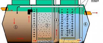
The main component of a screw compressor is the screw block (see figure below). It consists of a housing (1) in which a screw pair (2 and 3) is located.
The rotors in the middle part have thickenings on which a screw profile is cut. These screws are installed so that there is a gap between them in the range from 0.1 to 0.4 mm. The rotor pair is mounted either on bushings or on bearings. The rotation of the screws is synchronized using gears (4) mounted on the rotor shafts. To ensure the tightness of the housing, it is assembled with oil seals and seals.
Important! The drive screw of the unit has convex and wide teeth, while the driven screw has thin and concave teeth.
The compressor housing also contains cavities for cooling (5), into which liquid is supplied, if necessary. The compressor drive can be either direct or belt driven.
The operating principle of the rotor unit is as follows.
- When the screws rotate, air begins to flow through the inlet into the suction cavity, where the rotor pair is located. At this stage, air fills the screw cavities along the entire length (Fig. 1).
- When the rotors rotate towards each other, the suction volume is cut off from the inlet. At this stage, oil is injected to seal the gaps between the screws and lubricate them. Also, the incoming oil takes away the heat generated when air is compressed, performing a cooling function. As the screws are further turned, the volume of the working chamber decreases and the pressure in it increases.
- Further, at the moment when the screw cavities connect with the outlet of the compressor, compression in the chamber stops, and the compressed air-oil mixture begins to exit through the outlet window of the unit.
The design of a screw compressor is noticeably different from that of a piston unit. Below is a diagram of a screw compressor, which includes the following elements.
- Filter. Designed to clean atmospheric air sucked into the unit.
- Suction valve. Prevents the release of oil and air when the compressor stops.
- Screw block. It is the main working unit of the unit, consisting of a screw pair placed in a housing. A thermal protection sensor is installed next to the pipe (18), which turns off the engine if the temperature at the outlet of the screw block is above 105°C.
- Belt drive. Designed to transmit rotational motion from the engine to the screws. The drive consists of 2 pulleys. One pulley is installed on the motor shaft, and the other is installed on the drive shaft of the screw block.
- Pulleys. The rotation speed of the rotor pair depends on their size. The pulleys are connected to each other via a drive belt.
- Engine. Sets the rotational movement of the belt drive, which, in turn, drives the screw unit.
- Oil filter. Designed to clean oil returning to the rotor unit.
- Primary oil separator. In this unit, oil is separated from air using centrifugal force.
- Oil separating filter. Designed for secondary air purification from oil residues, that is, of higher quality. At the outlet of the filter, residual oil vapors in the amount of 1.3 mg/m3 can be detected in the air. This indicator is unattainable for piston devices.
- Safety valve. Ensures safety during operation of the unit. If the pressure in the oil separator (8) is exceeded, the valve will come into operation, relieving it to an acceptable level.
- Thermostat. Thanks to it, the optimal temperature of the oil composition is maintained. The latter can freely pass by the cooling radiator until it reaches a temperature of 72°C.
- Oil cooler. This tank receives heated oil, separated from the air, to cool it to the desired temperature.
- Air cooler. Allows you to cool the air before supplying it to the points of consumption to a temperature 15-20°C higher than the ambient temperature.
- Fan. Designed to cool all units of the unit.
- Idle valve. It is electro-pneumatic and is designed to control the suction valve (2).
- Pressure switch. Thanks to it, the device operates in automatic mode. The latest generation compressors have an electronic control system instead of a pressure switch.
- Pressure gauge. Shows the pressure level inside the unit.
- Outlet pipe. Through it, compressed air is supplied to the points of consumption.
- Device for visual inspection. Made in the form of a transparent thickening on the tube. With its help you can control the oil return process.
- Minimum pressure valve. Remains closed until the pressure rises to 4 bar. Since this element separates the pneumatic line from the compressor, it acts as a check valve when the unit stops or goes into idle mode.
All of the listed parts and components of the screw compressor are placed in a metal casing coated with a sound-absorbing compound. Depending on the manufacturer and model of the device, its design may differ slightly from that described above.
If we consider in detail the operating principle of a screw compressor, it looks like this (see figure below).
- When the unit is turned on, air begins to be sucked in through the filter (1).
- Next, the air enters the suction regulator (2), after which it moves to the rotor unit (3).
- In the rotor unit, air and oil are mixed and subsequently compressed. The oil enters the unit in precisely dosed portions.
- The air-oil mixture enters the separator (8) and passes through the cartridge (9), where it is separated into oil and air.
- Next, clean air passes through the cooling radiator (13) and exits the unit.
- The oil that was separated in the separator (8) returns to the rotor unit. The temperature of the returning oil determines in which circle it will move - large or small. If the oil is too hot, the thermostat valve (11) is activated and redirects it in a large circle through the oil cooler (12).
- Before entering the screw block from the radiator, the oil is cleaned in a filter (7).
- The screw pair is driven by a motor (6) and a V-belt drive (4 and 5).
Operating modes
Screw compressor units, even the simplest ones, have 5 operating modes.
- Start. This is the unit start-up mode, which eliminates the power supply overload. Voltage is supplied to the engine gradually, due to which it starts working only after 10-15 seconds. after pressing the power button.
- Idling. In this mode, the device is prepared for operation at full load. The rotors are driven by the engine and begin to pump air, but at low power.
- Work mode. In this mode, full operation of the unit is observed, the output of which is compressed air.
- Standby mode.
It is activated when a certain pressure is reached in the system. In standby mode, all processes in the compressor stop until the pressure in the system drops to the level at which the device turns on. Advice! This mode is very convenient when the compressor is used periodically during the working day, since there is no need to turn off the power to the unit. His work is only suspended for a certain period. - Stop. This mode leads to a smooth shutdown of the device. At first, it goes to idle, after which it turns off completely. Thanks to this mode, the likelihood of breakdowns and wear of parts due to sudden changes in pressure or voltage is reduced.
Some models of screw compressors have a Stop-Alarm mode. This mode is activated when any malfunction occurs in the equipment, or when the pressure and temperature in the unit increase to critical levels. The Stop-Alarm mode, as a rule, is triggered automatically. But to turn it on manually, there is a button located on the control panel of the device.
Work mode.
In this mode, pressure in the system begins to increase. The pressure gauge (17) located on the front panel shows the pressure inside the compressor, that is, in the area between the suction valve and the minimum pressure valve. The pressure in the line can be controlled using a pressure gauge located on the receiver. When first turned on, the pressure inside the compressor and in the line is almost the same. When the maximum pressure is reached, for example 10 bar, the pressure switch is activated and the compressor switches from operating mode to idle mode.
Types of screw compressors
Existing types of screw compressors determine their areas of use. For example, industrial oil-filled units are universal and widely used in various fields. But the use of oil-free devices is in demand only in those areas where a high degree of purification of compressed air is required, for example, in the food, chemical and pharmaceutical industries.
Oil-free devices
An oil-free compressor does not use oil to compress air as a lubricant and cool the rotor unit, therefore the compressed air produced by the device does not contain lubricant particles. Oil-free units are divided into 2 subtypes: screw dry compression and water-filled.
Dry compression screw compressors are equipped with synchronous motors that drive screws that are not in contact with each other. “Dry” devices have lower productivity (3.5 bar per 1 stage) than oil-filled devices. When connecting the second stage, you can increase this figure to 10 bar. But this measure will only increase the cost of the equipment, which is already quite high due to the use of twin engines.
Water-filled devices are the most technologically advanced and combine all the advantages of both oil-free and oil-filled devices. Water-filled devices are capable of compression forces of up to 13 bar (per 1 stage). Also, these models are environmentally friendly, since instead of oil for cooling they use ordinary water. Since water has high heat capacity and thermal conductivity, regardless of the level of air compression, it is heated by a maximum of 12°C due to dosed injection. It follows from this that by reducing the thermal load on the parts of the unit, their service life increases, and the safety and reliability of the equipment as a whole increases.
Important! The air leaving the water-filled unit does not need to be cooled, since the water that circulates in the system will always be at ambient temperature.
Water-filled compressors have virtually no waste during operation. Also, these devices are cheaper to manufacture, since their design does not include oil filters or containers for used oil.
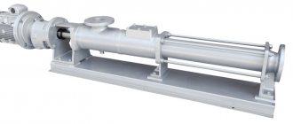
Oil-filled devices
The oil unit, as mentioned above, has 2 rotors, one of which is the driving one. To prevent physical contact between the rotors, oil is injected into the unit. It should be supplied at a rate of 1 l/min per 1 kW of device power. Oil compressors have a noise level of 60-80 dB.
In terms of engine power, compressors can be from 3 to 355 kW, and in terms of productivity - from 0.4 to 54 m3/min. High-performance equipment, as a rule, is stationary and installed in workshops. But there are still mobile screw compressors, both gasoline and diesel.
Separator
To ensure that the compressed air leaving the screw compressor contains a minimum amount of oil, a separator is necessarily used in its design.
The separator can be external (in low-power compressors) or built into the oil reservoir.
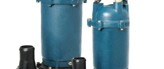
Appearance of the built-in separator:
Built-in separator
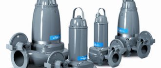
External separator:
External separator
Sectional view of the separator showing oil and air flow:
Sectional view of separator
Due to the presence of a separator in the design of the screw compressor, the oil content in the compressed air at the outlet does not exceed 3 mg/m3.
Common malfunctions of screw compressors and their elimination
Long-term operation of any equipment leads to the fact that it requires either servicing or serious repairs. Compressors whose main component is a rotor unit are no exception.
Do-it-yourself repair of screw compressors is quite possible in the following cases:
- the device is difficult to start;
- the compressor does not restart;
- there is no compressed air in the outlet pipe of the unit;
- low productivity;
- excessive oil consumption;
- involuntary activation of the safety valve;
- turning off the device by thermostat;
- turning off the unit with a network breaker;
- breakdown of the rotor unit;
- high blood pressure.
The device does not start well
The reason that the unit is difficult to start may be the low ambient temperature. The compressor will start only after the room in which it is installed has warmed up.
The device does not restart
This breakdown is caused by poor closing of the suction valve. The problem is solved by cleaning the valve. If this procedure does not solve the problem, the suction valve should be replaced.
No compressed air
If there is no compressed air in the outlet of the device, then this is a sign that the regulator is closed. To eliminate the malfunction, you will need to check the operation of the pressure switch. It is this unit that supplies power to the valve, which is electromagnetic, which, in turn, is connected to the regulator.
Poor performance
A decrease in equipment performance is also associated with the closure of the regulator. In this case, the breakdown is caused by clogging of the latter. In order for the performance of the device to return to normal, it is necessary to remove the suction filter, open or dismantle the regulator, and clean it thoroughly.
Excessive oil consumption or leakage
High oil consumption can be caused by a broken filter installed in the oil separator, or leaking seals of the same filter. In both cases, the problem is solved by replacing these parts.
Important! An open regulator or excessively high pressure in the system can cause an oil leak. In the first case, you should check the serviceability of the solenoid valve and regulator. In the second, check the pressure gauge.
Opening the safety valve
This breakdown can occur if the oil separator filter is clogged. It is necessary to check whether there is a pressure difference between the oil separator, that is, its reservoir and the pipeline containing the compressed air. The problem is solved by replacing the filter.
Thermostat tripping
The thermostat turning off the unit can be caused by several reasons.
- High ambient temperature. You should ensure that the room with the equipment is well ventilated, then press the “reset” button and reboot the device.
- Oil cooler clogged. It is necessary to clean the cooler using a solvent liquid.
- Low oil level. The required amount of the latter should be added.
- Thermostat malfunction. The part should be replaced with a working one.
Switching off the engine with a power breaker
A tripped circuit breaker can cause low line voltage. You should check the voltage and, if it is normal, restart the device by pressing the “Reset” button.
Also, the circuit breaker may trip if the engine overheats. First of all, you need to check the heat dissipation from the electric motor. If the heat removal mode is not violated, then restart the equipment. If the restart does not occur, you should wait a few minutes and try again.
Broken rotor unit
If you pay attention to the description of the rotor unit given above, it will become clear that it can only be repaired if the bearings fail .
In case of jamming of the rotors, the repair of the screw units should be entrusted to the specialists of the service center.
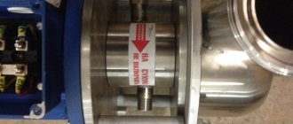
Check Valve / Strainer
The oil separated from the compressed air in the separator must be returned to the compressor circulation circuit. For this purpose, a special oil return line is used, which includes a check valve and a strainer.
Oil return line
In order for the oil return process to be observed in real time (this is necessary for diagnostic purposes), some parts of the oil return line are made transparent.
Oil return line
Description [edit | edit code ]
Bearings are limited in size by two rotors located at a fixed distance from each other. This is the reason for their limited resource, which, depending on the size of the model, is stated to be 30-60 thousand hours, after which they need to be replaced. In addition, there are axial loads, since compression occurs between the two rotors, and the compressed air presses on the screws from the center to the walls.
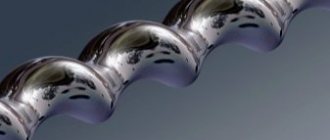
Screw block [edit | edit code ]
The design of the screw block consists of two massive screws and a housing. In this case, the screws are at a certain distance from each other during operation, and this gap is sealed with an oil film. There are no rubbing elements. Dust and other solid particles and even small objects that enter the screw unit do not cause any damage and can only damage the oil system of the compressor itself. Thus, the service life of the screw block is practically unlimited and reaches more than 200-300 thousand hours. Only the screw block bearings are subject to routine replacement.
Screw technology operates over a wide range of rotation speeds, allowing for variable performance. Allows the use of both a standard loading/unloading/stop system and frequency control of productivity. With frequency regulation, the engine revolutions per minute and, accordingly, the rotation speed of the screw unit change over a wide range, which allows you to adjust the performance in accordance with the air intake, thereby saving energy.
Maintenance [edit | edit code ]
A pneumatic valve that is simple in design (open/close) with an almost unlimited service life is used with timely replacement of repair kits - once every 12 thousand operating hours. Every 3000 hours:• Replace the air filter;• Replace the oil filter; Oil change (if using mineral oil)
Every 6000 hours:• Replace the air filter;• Replace the oil filter;• Change the oil (if using synthetic)• Replace the oil separator.
What characteristics should the oil have?
High-quality oil for a screw compressor should have the following properties:
- Viscosity-temperature properties. Thanks to them, oil is supplied in sufficient quantities to the compressor, fills the gaps between the rotor and the housing, and lubricates the bearings well
- Wetting properties. Provide heat removal and cooling of interacting parts
- Detergent and dispersing properties. Allow the compressor to operate smoothly, keep the rotors clean, and reduce the risk of clogging and cold sludge deposits
- Resistant to wear and high pressure. The active substances contained in oils form a wear-resistant film that can withstand high pressures. Thanks to this, the equipment lasts much longer
- High oxidative stability. The oil should not oxidize quickly when exposed to oxygen and high temperatures. Otherwise, carbon deposits will form, which will negatively affect equipment performance.
Thus, to service screw compressors, you should use oils that have the properties described above. If at least one of these characteristics does not satisfy the requirements of the equipment or its operating conditions, then such liquid is not recommended for use.