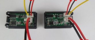
Almost every craftsman who often works with metal knows the electrical circuit of an angle grinder. The grinder is the tool most often used for cutting metal. This tool is a source of increased danger, so you should check the serviceability of the electrical and mechanical components of the structure before each use.
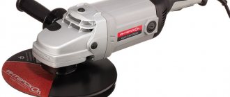
Schematic diagram of the grinder.
An angle grinder, which in the post-Soviet territory is called “grinder”, was the dream of every home craftsman 3-4 decades ago. 30-40 years ago, this working tool was produced by one manufacturer, the Eltos-Bulgarka plant, located on the territory of Bulgaria in the city of Plovdiv. Currently, manufacturers offer consumers various models and modifications of this tool, but the main design components have remained virtually unchanged. Most of the structural elements on different models and modifications differ only in size.
How to connect a grinder button for replacement
Home page » For blacksmiths » How to make » How to connect a grinder button for replacement
The angle grinder is ready for use only after pressing the start button (switch).
If it fails, it will be impossible to perform a certain amount of actions using it. Repair work needs to be carried out . It is usually quite difficult to repair the button itself due to contact burnout. More often than not, a broken button is simply replaced with a new one .
Electrical part of the grinder
There have been no significant changes in the design of the instrument recently. The body is oblong, inside there is a gearbox with a motor, a handle on the side and a protective casing on top of the abrasive wheel.
The tool does not always work smoothly, and there are circumstances when it becomes necessary to simply disassemble it and lubricate some elements with oil as a preventative measure. To do this, you need to know the design and be able to use drawings, including the electrical circuit of the angle grinder. The ability to correctly read technical documents and understand how equipment works will help perform any type of repair work.
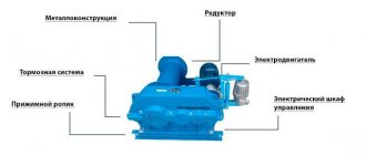
The electrical circuit of the grinder contains the following elements that ensure its movement:
- collector;
- gearbox;
- handle holders;
- anchor;
- electric brushes;
- stator;
- cable for power supply.
Each of these elements has its own purpose; if any of them breaks, the tool will not work.
Angle grinder device
The start button is part of the design elements of the angle grinder, each of which performs its own specific task in ensuring the functioning of the power tool. The main ones, of which are the following:
- power cable for connecting the angle grinder to the network;
- stator – a stationary part of the electric drive, consisting of several excitation coils;
- anchor (rotor) – the moving part of the electric drive of the angle grinder;
- collector - part of the rotor, made in the form of insulated copper plates, providing a connection to the stator;
- brushes – provide sliding contact for transmitting current between the moving and stationary parts of the electric drive;
- gearbox - converts the rotation of the rotor created by electromagnetic interaction into spindle ;
- the design is protected from external influences by housings made of impact-resistant plastic for the electrical part and aluminum alloy for the gearbox;
- for ease of use, the grinder is equipped with a removable handle holder ;
- There are buttons on the body: an on/off button and a lock button for replacing the working tool.
Metabo W 750-125 angle grinder body, handle, shutdown and stop buttons (red and black). Photo 220Volt
Some power buttons have a soft start function, which makes the grinder more convenient and durable. There may be a speed regulator on the body, which significantly expands the functionality of the angle grinder with various materials.
Device
The operating principle of any electric drive, including an angle grinder, is based on the interaction of the stator and rotor according to the laws of physics operating in an electromagnetic field. In this case, the stator is a stationary element that creates this electromagnetic field. It is the source of the creation of forces that rotate the movable rotor and convert electrical energy into mechanical energy.
The stator is a core made of sheets of electrical steel . This stacked design prevents the core from getting too hot during operation, as it reduces the possibility of eddy currents occurring. The core has grooves for windings , which are wound in a certain way and act as an inductor, which actually creates an electromagnetic field.
408-105 Stator for Hitachi G18SE3 and HAMMER angle grinders. Photo 220Volt
The windings are wound from copper wire ; the winding patterns depend on the functional purpose of the equipment that includes the electric drive. The windings are impregnated with electrical insulating varnish , which prevents short circuits of the turns and breakdown on the core body, which additionally has insulation from the windings in the form of electrical insulating cardboard or other similar material located in the grooves. In grinders, the stator is tightly mounted in a plastic impact-resistant housing , which serves as both a protective and load-bearing element.
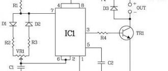
Launch scheme
The design of the grinder, the energy source of which is electric current, is capable of converting it into mechanical. The interaction of all components of the angle grinder is shown in the schematic diagram for connecting its electric drive.
- Once the power cord is plugged into the outlet and the starter is turned on, electrical current is applied to one of the brushes.
- After passing through the commutator winding, the current appears on another brush , through which the stationary stator windings are supplied .
- The magnetic fields created by the stator and rotor windings interact with each other, causing rotation of the rotor mounted in bearings . Along with it, the torque occurs on the bevel gear mounted on the anchor. Another bevel gear, working in tandem with the first, rotates the spindle with the working tool of the angle grinder.
- Additional taps of the stator or rotor windings allow you to increase the functionality of the power tool by creating various control systems.
- Through the contacts of the commutator plates, signals about the rotor speed are transmitted to the tachogenerator or Hall sensor. With their help, the grinder maintains the required speed.
- To protect the angle grinder from overheating, there is a thermal protection unit. It turns off the tool if the sensor shows the maximum permissible temperature of the control surface of the angle grinder.
Scheme of operation of the grinder. Source here
Understanding the role of each of the elements included in the electrical circuit of the angle grinder allows you to correctly determine the cause of its breakdown. If the cord, button and brushes are in good condition, you should pay attention to the condition of the electric drive.
Results
When you find the desired contact using a multimeter, you can make the connection. For clarity, I recommend that you watch the video below. It talks quite well about solving problems with the stator. There are also detailed instructions on how to deal with part malfunctions.
How to connect a power tool? This question very often arises when repairing power tools when there is no electrical circuit, the device is partially or completely disassembled, disassembled and, in addition, has been subjected to repeated, inept repairs.
Wires stick out in different directions, some of them are connected to each other, the ends of others are exposed. It would seem that it is impossible to understand this chaos, in which there is no logic.
In fact, you can connect any electric motor correctly and without problems, even without knowing the circuit. You just need to know its type, design features and at least the basics of the theory.
I’ll show this using the example of connecting a Macita3612C router.
It seems that it is impossible to understand this chaos of wires without a diagram, but believe me, this is not so. Moreover, some wires can be dispensed with, while others are simply not needed.
Sometimes, when repairing or restoring the functionality of a power tool, it becomes necessary to connect the device to the network while maintaining all the functionality that the power tool originally had, but only wires stick out from the body, quite a lot of them (in my case 6), and the electrical circuit can’t be found anywhere . What to do? In fact, everything is not so scary and difficult.
A distinctive feature of a commutator electric motor is the commutator unit.
It is not at all necessary to know what and how was done initially. In order to connect the electric motor of the tool, you need to do the following:
- Find the supply circuit.
- If necessary, connect capacitors.
- Connect the switching device.
Method for finding power wires
In hand-held power tools for any purpose, as a rule, a universal commutator motor (UCM) is used. This versatility is very conditional and only means that the engine can theoretically operate on direct or alternating current. In practice, during repairs, this feature cannot be used; it is more important to know the circuit diagram of the UCD. By looking at which you can draw an important practical conclusion.
One of the bundle of wires entering the motor housing must certainly be connected to one of the stator windings, and through it to the contact pad of the brush.
To make sure of this, you need to unscrew or remove both plugs of the brush holders and remove the brushes. Then, touching one multimeter probe to the contact pad of one of the brushes, use the other probe to ring all the conductors in sequence. If the desired wire is not found, move to another site. In the end, the right guide will definitely be found.
In this case, it is convenient to use a multimeter with an audio signal. Depending on the design features of the device under study, the resistance in some circuits may be very small and this can be misleading.
How to change the power button, connection process
The main symptom that the starting device is out of order is the lack of reaction from the angle grinder when the button is brought into working position. This defect can also be caused by critical wear of the commutator brushes and a break in the power cable wire.
Therefore, it is necessary to carry out diagnostics using an electrical multimeter or, in its absence, using an open circuit indicator. To do this, it is imperative to remove the plastic case that protects the electrical part of the angle grinder in order to get to the button contacts, the connection point of the power cable and the ability to check the operation of the brushes.
If the contacts are not called, proceed to replace it. The entire process, including diagnostics, is described in the video below. It should be noted that the button that failed here is being replaced with a similar one in design. In passing, the condition of the brush assembly of the angle grinder is assessed, and recommendations are given on a possible simpler replacement of the brushes.
Do-it-yourself Bosch grinder disassembly
For the owner of a power tool, knowledge of its structure and the ability to disassemble it is a mandatory task.
Knowing the procedure for disassembling an angle grinder allows you to independently carry out work such as changing grease, changing bearings and carbon brushes.
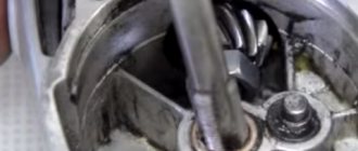
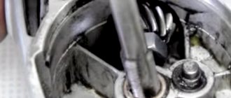
To disconnect the gearbox housing pos. 821 from the stator housing pos. 888, you need to disassemble (remove) the body of the grinder handle pos. 24.
This operation must be performed to remove the carbon brushes pos. 810 holding the rotor commutator.
At the second stage, unscrew 4 (four) screws, pos. 61, securing the gearbox and stator housings.
Having pulled out the rotor together with the gearbox, begin disassembling the gearbox.
Repair of a Bosch angle grinder begins with disassembling the gearbox pos. 821. Disassembling the gearbox begins with unscrewing 4 (four) screws, pos. 60. As a rule, the screws are screwed in with sealant at the factory. You will have to make some effort.
Let's note it right away! Low-power Bosch angle grinders use spur gears in the gearbox. Grinders with a power of over 1000 W use helical gears in their gearboxes.
How to remove the driven gear
By removing the gearbox cover, you can get the helical gear assembly, pos. 26.
To remove the gear, you need to use a press or puller. But using a puller is difficult because it requires the use of special thin jaws.
Before removing the helical gear, check the backlash of the gear connection, the integrity of the teeth, and the contact patch.
A bearing, pos. 50, is pressed onto the spindle shaft, pos. 26. If the bearing has a lot of play, is noisy when turning, or the lubricant has dried out, it is preferable to replace it.
To remove the bearing, you need to remove the gear, retaining ring and dismantle the bearing. If, when dismantling the rotor shaft assembly, the bearing remains in the gearbox housing, dismantling the bearing is carried out using a hammer and a soft tool.
How to remove the drive gear of a Bosch angle grinder
The drive gear pos. 27 is removed from the rotor shaft in the following sequence:
- Hold the rotor with your hand and, using an open-end wrench, unscrew the nut pos. 45 counterclockwise;
- remove the washer pos. 59.;
- pull out the drive helical gear pos.27.
Visually check the integrity of the gear teeth and contact patch.
If the gears are heavily worn (licked), or there are chipped teeth, they must be replaced. Moreover, gears are always replaced in pairs.
Low-power Bosch angle grinders use a needle bearing as a support bearing in the gearbox.
Repair your Bosch earmachine guns with your own hands, strictly follow the included instructions. If you need to remove a needle bearing from its housing, some quick thinking is required. Its dismantling is carried out only when destroyed.
To remove a damaged bearing race, you can use a proven method.
Select a tap with a diameter slightly larger than the inner diameter of the damaged needle bearing race. The tap is secured in the screwdriver chuck and carefully screwed into the holder at low speeds. When the tap reaches the bottom of the gear housing, it will begin to lift the cage.
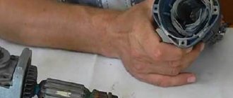
In addition to the needle bearing of the spindle shaft, Bosch angle grinders use two more bearings mounted on the rotor shaft.
How to remove bearings from the rotor of a Bosch angle grinder
To remove bearings from the rotor pos. 803 of a Bosch angle grinder, it is recommended to use pullers.
Bearing pos. 15 near the manifold can be easily removed, but removing bearing pos. 14 from the impeller side is complicated by the fact that a number of preparatory operations must be performed.
Bearing pos. 15 is closed with a soft rubber seat. A similar rubber protection, pos. 33, also covers the bearing, pos. 14.
To dismantle the bearing pos. 14, you need to unscrew the nut pos. 45, remove the spur gear pos. 17 and the plastic protection pos. 33. Using a puller, you can easily remove the bearing from the rotor shaft.
What if there is no puller? A vice, two metal strips and a hammer with a soft metal attachment will come to the rescue.
Disassembling a Bosch grinder
How to connect directly without a button
If an urgent need arises when leaving the start button, you can supply power directly to the two network wires extending from it into the angle grinder. In this case, the capacitor, which has the main function as a spark arrester when the brushes operate, will also not be involved in the work. And this despite the fact that when the plug is turned on/off from the socket, transient processes will intensify and increase the tendency to form sparks.
an electronic soft start circuit works together with the button , which eliminates a sharp increase in current during startup and makes working with the angle grinder convenient and safe. It is clear that in this mode of operation the angle grinder will quickly fail . It is better to replace or, if possible, repair the start button.
The purpose of each power supply element of the angle grinder 125
The grinder circuit includes several elements that ensure its smooth operation.
Purpose of elements for power supply:
- Anchor. This part facilitates the movement of the abrasive wheel for cutting metal products and workpieces. It is necessary to create greater speed in relation to the disks to ensure their rotational movements. And, accordingly, at a higher anchor speed, the power indicators of the tool are higher.
- Collector. This is a platform located on an anchor to which all power lines are connected. Its main function is to transmit signals through the windings to the motor and control unit so that the elements correctly perceive this information. The element immediately catches your eye when you remove the cover from the case, as it has a polished surface and its dimensions are quite large.
- Electric brushes. The purpose of these elements is to supply electric current to the cable. During normal operating placement, a glow will be observed emanating from them through the opening provided for ventilation. If it is noted that this is absent, is weak or almost unnoticeable, then this is an indicator that there is a problem with the electric brushes.
- Gearbox. The main structural part for the electrical circuit and for the entire technical device as a whole. Its function is to transfer electricity from the armature to the abrasive disc. This ensures rotation, which creates work. In fact, only the gearbox helps to increase the speed and power characteristics of angle grinders.
- Stator. This is the most complex knot that complements the grinder device. It is in it that the windings of both the armature and the rotor are located, which are the primary mechanisms that provide movement. The windings of the stator coil are clearly calculated until the last turn. If this element fails, it is unlikely that an inexperienced worker will be able to restore the winding. This happens, but in exceptional cases. It is best to contact a specialized workshop regarding stator rewinding.
Read also: Weaving rubber bands on slingshot keychains
How to replace the retainer
There is another button on the gearbox housing of the angle grinder, with which you can quickly change a worn or broken working tool. Locking the spindle by pressing this device against rotation makes it easy to replace. It also fails due to improper operation of the grinder (pressing a button while the spindle is rotating) or when changing a tightly clamped working tool. You can read in detail how to replace the lock in the description at the link “Bulgarian stopper button”.
Connection diagram
The power source for the stator coils of angle grinders, which are usually made of two unconnected windings, is a household electrical network . Using the start button, voltage from the network cable is supplied mechanically to one of the two contacts of each winding. The other contact is connected to the graphite brush of the commutator assembly. Thus, two coils are connected in parallel to the commutator lamellas, with the help of which the circuit is closed with the rotor coils.
READ How to connect 2 web cameras to a computer simultaneously for video surveillance
I ask for theoretical assistance in repairing an angle grinder (electrician)
Question about repairing an angle grinder. Help! Bulgarian Hertz (sort of) power 2050W
I had to work. It was hot. In short, something puffed. I took it apart, and there the soft start unit (with three wires) turned black. I opened it a little, and there a certain element very reminiscent of a transistor was blown up.
The angle grinder was disassembled piece by piece, cleaned, purged. Visually, the winding was intact, both on the shaft and on the stationary part. brushes and commutator are in more or less condition
I found a similar one on the market, but it was used (they gave it away for free and they said it had to be working), the diagram is drawn on the case (there are abc wires, and how to connect) what and where. Connected. Assembled. I press the button and it explodes. The block explodes again. Why? what else can you see? Could there be a turn short circuit somewhere (not visually visible) and that’s why?
Maybe you can immediately apply phase and zero to the brushes, that is, directly? but there is a small capacitor installed near the button. For what?
grinder repair burned out stator
Hello Pavel. I believe that with this malfunction you will also need to inspect and check for resistance the stator winding of the electric motor of the angle grinder. A likely reason for rapid heating of the electric motor is the cause of the interturn short circuit in the winding, that is, the insulation is broken (coating the wires with varnish). When the rotor suddenly stops, a current is created in the electric motor circuit that significantly exceeds the rated value. This is just my personal opinion and I would also like to find out the worldview of my friends, participants in the correspondence. Victor.
Hello! Please tell me - after changing the anchor of the hammer drill https://rotorua.com.ua/product/jakor-perforatora-einhell-858/ the barrel of the hammer drill began to spin in the other direction. What are the prerequisites? Defective anchor or some kind of discrepancy? thanks for the answer.
Hello. Maybe you need to switch reverse? If, when switching reverse, the hammer drill barrel continues to spin in the other direction, try changing the wires going to the brush holders.
Source
Electrical Diagram of the Grinder
89243 views
In the last article I told you how to connect and start a 380 Volt motor in a single-phase 220 V electrical network. Now I will talk about how to connect a single-phase electric motor from a broken washing machine, vacuum cleaner, etc. It can be successfully used for other purposes in household, for example, to drive a sharpener, polishing machine, lawn mower, etc.
Connection diagram for a 220 Volt commutator motor
Electric drills, rotary hammers, grinders and some models of automatic washing machines use a synchronous commutator motor. It successfully starts and works in single-phase networks without unnecessary starting devices.
In order to
connect a commutator electric motor , it is necessary to connect the two ends No. 2 and No. 3 with a jumper, one coming from the armature, and the other from the stator.
And connect the remaining 2 ends to a 220 Volt power supply. Remember that when connecting a commutator electric motor without an electronics unit, it will only operate at maximum speed, and when starting there will be a strong jerk, high starting current, and sparking on the commutator.
The motor may also have a 2-speed motor, then the 3rd end will come out of the stator from half of its winding. When connected to it, the shaft rotation speed will decrease, but this increases the risk of insulation failure when starting the motor.
To change the direction of rotation, it is necessary to swap the ends of the stator or armature connection.
Connection diagrams for single-phase asynchronous electric motors
If single-phase electric motors had only one winding in the stator, then the electromagnetic field inside it would be pulsating rather than rotating. And the launch would occur only after unwinding the shaft by hand. Therefore, to independently start asynchronous motors, an auxiliary or starting winding is added, in which the phase is shifted by 90 degrees using a capacitor or inductance. The starting winding pushes the rotor of the electric motor at the moment of switching on. The main connection diagrams are shown in the figure.
The first two circuits are designed to connect the starting winding while the motor is starting, but not more than 3 seconds in duration. To do this, use a relay or a start button, which must be pressed and held until the engine starts.
Design features of the Makita angle grinder
Before it completely breaks down, the grinder usually starts giving distress signals. Diagnosis is best carried out according to the principle from simple to complex. In addition, damage to the magnetic circuit and commutator can cause failure. The lifespan of these devices is usually limited to several years; of course, it all depends on the intensity of use. How to make repairs If the angle grinder does not start when the start button is turned on, then there is reason to believe that the reason here is not so serious, and it is not difficult to carry out repair work yourself. Remove the nut, take out the flat washer pos. Synthetic fabrics can catch fire or be damaged by burning.
Repairs can be done at home. It is one of the parts of the engine with an armature located inside.
Pieces of material being ground may have a high temperature. User reviews confirm the well-deserved popularity of the tool both among craftsmen who professionally use this angle grinder in production, and among amateurs who like to tinker at home.
If unsuccessful, the existing solder must be replaced. This part is located inside the electric motor and begins to rotate during operation.
In this case, both the rotation speed of the working disk and the power it develops are subject to adjustment; The stator is the part of the electric motor of the angle grinder in which the armature and rotor rotates. grinder repair
Electrical diagram of an angle grinder with a capacitor
After a certain period of use, the grinder is characterized by such breakdowns as wear of the graphite brushes, burnout of the windings
stator no further. Naturally, wear itself is not excluded, not in terms of mechanics. To fully familiarize yourself with the topic: “How to repair an angle grinder,” let’s look at the electrical circuit of a commutator AC motor, since such an electric motor is installed in the angle grinder.
AC brushed motor circuit diagram
The diagram (Fig. 1) shows the electrical connections of the stator and rotor windings of non-graphite brushes. Graphite brushes in the electric motor are installed in brush holders. The brushes are in contact with the commutator lamellas. Some ends of the stator windings are connected to an external energy source. The other ends of the stator windings are connected to graphite brushes, electrical
the circuit is closed on the rotor windings.
The regulator is connected by wires to the commutator motor circuit in series. The connection diagram must be indicated on the regulator body itself, or in the grinder’s operating manual.
The device of the grinder
According to the design of the grinder
, our indicated in the figure does not need any specific explanation. Using driven non-driving bevel gears, rotation is transmitted from the electric motor to the gearbox shaft.
Commutator motor malfunctions
The device of the grinder
With such a delay, there is no particular discomfort when starting to work with the tool, and at the same time, the power tool itself is not subject to excessive loads from a sudden start. So let’s say the stator windings burn out (Fig. A screwdriver can also be used to remove brushes. Energy is transferred from the network to the anchor using graphite brushes.
If the electrical circuit of the angle grinder E device is broken, the protective casing should be removed and checked with a tester for the presence of voltage in the trigger mechanism. If the electric current is supplied to the start button, but is not transported further, then the breakdown of the tool consists in the failure of the start button.
Unscrew the gear housing from the angle grinder motor housing.
With such a delay, there is no particular discomfort when starting to work with the tool, and at the same time, the power tool itself is not subject to excessive loads from a sudden start.
Its task is to translate the signals passing through the windings into a language understandable to the engine and control unit.
The brushes wear out and shrink. How to disassemble the gearbox was described above.
The device of an ordinary grinder. Makita angle grinders have their own pre Diagnostics of the angle grinder Stopped turning on How to find a break Tool repair
Stators
408-317 Stator for BOSCH GWS7-125/GWS7-115 HAMMER. Photo 220Volt
The compact design of an electric drive and a mechanical gearbox , which increases the torque on the working shaft, allows the angle grinder to be successfully used as a hand-held power tool in terms of weight and overall dimensions. The ease of replacing attachments on the working spindle makes the grinder a convenient universal device for processing a wide variety of materials (metal, wood, plastic, stone and many others). The grinder is popular both among users who perform simple work at home, and among professionals who perform complex work that requires high qualifications. The main structural element of the electric drive of an angle grinder is the stator . This article describes the features of this one of the main components of the electrical part of the angle grinder.
READ How to connect running lights to an Outlander