When making homemade power supplies or chargers, craftsmen often equip such devices with digital voltammeters. The price of such devices fluctuates around a few dollars, and their accuracy allows you to completely forget about dial gauges. Given the wide range of modern voltammeters, you may encounter problems connecting them. Today our article is devoted to the most popular voltammeters and their connection diagrams. Also, in addition to the standard circuit, we will describe how to connect a voltammeter to a charger
Voltage measurement. Voltmeter.
A device designed to measure voltage is called a voltmeter.
And, unlike an ammeter, it is connected to the circuit parallel to the section of the circuit at which the voltage needs to be determined. And, again, in contrast to an ideal ammeter, which has zero resistance, the resistance of an ideal voltmeter should be equal to infinity. Let's figure out what this is connected with: If there were no voltmeter in the circuit, the current through the resistors would be the same and determined by Ohm's Law as follows:
I_1 = I_2 = \frac{U}{R_1 + R_2} = \frac{30}{10 + 20} = 1
So, the current value would be 1 A, and accordingly the voltage on resistor 2 would be equal to 20 V. This is all clear, but now we want to measure this voltage with a voltmeter and turn it on in parallel with R_2. If the resistance of the voltmeter were infinitely large, then no current would simply flow through it (I_B = 0), and the device would not have any effect on the original circuit. But since r_B has a finite value and is not equal to infinity, current will flow through the voltmeter. In this regard, the voltage across resistor R_2 will no longer be the same as it would have been in the absence of a measuring device. That is why the ideal voltmeter would be one through which no current would pass.
As with the ammeter, there is a special method that allows you to increase the voltage measurement limits of the voltmeter. To do this, it is necessary to connect an additional resistance in series with the device, the value of which is determined by the formula:
R_D = r_B\medspace (n\medspace-\medspace 1)
This will cause the voltmeter reading to be n times less than the measured voltage. As usual, let's look at a small practical example:
Here we added additional resistance R_3 to the circuit. Our task is to measure the voltage across the resistor R_2:\medspace U_2 = R_2\medspace I_2. Let's determine what result the voltmeter will give us when turned on in this way:
U_2 = I_2\medspace R_2 = U_B + I_B\medspace R_3
Let's substitute the expression for calculating the resistance of the additional resistor into this formula:
U_2 = U_B + I_B\medspace (r_B\medspace (n\medspace-\medspace 1)) = U_B + I_B\medspace r_B\medspace n\medspace-\medspace I_B\medspace r_B = U_B + U_B\medspace n\medspace- \medspace U_В = U_В\medspace n
Thus: U_B = \frac{U_2}{n}. That is, the voltmeter readings will be n times less than the voltage value that we measured. So, using this method, it is possible to increase the measurement limits of the voltmeter!
At the end of the article, a few words about measuring resistance and power.
To solve both problems, it is possible to use an ammeter and a voltmeter together. In previous articles (about power and resistance), we dwelt in detail on the concepts of resistance and power and their relationship with voltage and resistance, thus, knowing the current and voltage of an electrical circuit, we can calculate the parameter we need. Well, in addition, there are special devices that allow you to measure the resistance of a section of a circuit - an ohmmeter - and power - a wattmeter.
In general, we’ll probably finish here for today, stay tuned and visit our website! See you soon!
Connection diagrams and methods
The question often arises of how to connect an ammeter, in series or in parallel. Connecting the device in question into an electrical circuit break is not difficult. For safety reasons, this procedure is performed when the power source is turned off. You need to make sure in advance that the maximum current will not exceed the permissible values of the device. Such scales are duplicated in the accompanying technical documentation. When the supply voltage is applied, readings are taken. You need to wait until the needle stops oscillating. When it moves in the opposite direction, the polarity of the connection changes. If the current is too high, additional shunting is used.
The connection diagram of the device can be direct or indirect. In the first case, the device is directly connected to the electrical circuit between the power source and the load.
Before connecting the device, you must consider:
- direct or alternating current in the electrical network;
- Is the polarity of the device correct?
- the arrow of the device should be located beyond the middle of the scale;
- limits for measuring the maximum possible current surges in the circuit;
- whether the external environment meets the recommended indicators;
- Is the measurement location free from vibration?
Connecting the device
In DC circuit
Direct current can pass through different electrical circuits. As an example, we can cite all kinds of chargers and power supplies. To repair such devices, the technician must have an understanding of how the ammeter is connected to the electrical circuit.
At home, such skills will also not be superfluous. They help a person who is not too keen on radio electronics to determine for himself, for example, the time it takes to charge the battery from a camera.
To conduct the experiment, you will need a fully charged battery with a nominal voltage of, for example, 3.5 V. In addition, you need to use a lamp of the same rating to create a series circuit:
- battery;
- ammeter;
- bulb.
The entry that is marked on the measuring device is recorded. For example, a lighting fixture will consume 150 milliamps of electricity, and the battery has a capacity of 1500 milliamp-hours. Therefore, it will work for 10 hours, delivering a current of 150 mA.
DC circuit
To charger
The question often arises of how to properly connect an ammeter to a charger. When using a charger, the need arises to measure the current. This will make it possible to control the process of accumulating electricity by the battery, and avoid overcharging and undercharging. As a result, the service life of the battery will increase significantly.
When operating a large number of technical devices, it becomes necessary to control the current strength. The ammeter needles or indicators on the monitor of a discrete device will show the operator such a physical parameter. The measurements taken are needed to maintain the operating condition and to signal the occurrence of an emergency.
Connecting to the charger
Varieties
The measurement accuracy of the device in question will depend on the principle of influence and the type of device. According to the common classification, all ammeters can be divided into the following types:
- Magnetoelectric.
- Electromagnetic.
- Electrodynamic.
- Thermoelectric.
- Digital.
- Ferrodynamic.
There are other specialized devices to measure current strength. They are used in narrow-profile areas; they are not as widespread as those mentioned above.
Electromagnetic
Devices with an electromagnetic operating principle are not equipped with a moving coil, unlike magnetoelectric types of devices. The design of the devices in question is much simpler. The housing contains a special device and 1 or more cores installed on the axis.
The type of ammeter under consideration has less sensitivity compared to a magnetoelectric device, therefore the accuracy of the device’s measurements will be significantly lower. The advantages of such devices will be the versatility of operation. This means that they are able to measure the current strength in a DC and AC circuit. This will significantly expand the scope of use of such a device.
Electromagnetic ammeter
Magnetoelectric
The principle of action of this type of device is based on the interaction of a magnetic field and a moving coil, which is located in the design of the device.
The advantages of the product in question will be low energy consumption during operation, increased sensitivity and accuracy of measurements. Each magnetoelectric device is equipped with a uniform graduation of the measuring scale. This will make it possible to make highly accurate measurements.
Important! The disadvantages of the device in question include the complexity of the internal structure and the presence of a moving coil. Such a product is not considered universal, since it is only suitable for direct current.
Despite the disadvantages of the ammeter, this type of device is widely used in various industrial areas and in laboratories.
Magnetoelectric ammeter
Thermoelectric
This type of device for measuring current is used for electrical circuits with high-frequency current. The devices have a magnetoelectric mechanism consisting of wires with a soldered thermocouple. During the passage of current, the wiring strands are heated. The greater the force, the higher the temperature rises. Using these parameters, a special mechanism will convert heating into current indicators.
Thermoelectric ammeter
Electrodynamic
The operating principle of the devices under consideration is based on the interaction of electric fields of currents passing through magnetic coils. The ammeter device includes a moving and a fixed coil. Universal operation on each type of current will be the main advantage of the types of ammeter under consideration.
Among the disadvantages, it should be noted that they are more susceptible, since the devices will react to even the smallest magnetic fields that are located in close proximity. Such fields can create significant interference for the ammeter in question, which is why such devices are used only in places protected by a screen.
Electrodynamic ammeter
Ferrodynamic
Such devices are distinguished by the highest efficiency and measurement accuracy. Electromagnetic fields that are located in close proximity to the ammeter will not have a significant impact on the device, therefore there is no need to install auxiliary screens for protection.
The device of such a product includes a closed ferrimagnetic wiring, a core and a fixed coil. This design makes it possible to improve the reliability of the device. Therefore, ferrodynamic types of ammeters are often used in military applications and defense enterprises. The main advantages of the device also include comfort and ease of use, measurement accuracy in relation to the previously discussed types of devices.
You may be interested in Features of an AC ammeter
Ferrodynamic ammeter
Digital
The most modern and comfortable type of device for measuring current strength. They do not have arrows that fluctuate regularly. Such devices are equipped with a monitor where indicators will be displayed that display the current strength in amperes. At the same time, they will provide fairly accurate information. Important advantages of digital devices include their immunity to vibration and shaking.
In view of this, it is possible to measure the current strength in vehicle wiring on the go, without stopping. Most digital devices come with waterproof and shockproof casing, making them more durable for use in harsh environments. Since the device does not have an arrow, it can be placed horizontally, vertically or at an angle. The direction of the devices during measurement does not in any way affect the data obtained.
Digital ammeter
Important! Digital devices are not afraid of small mechanical shocks that are possible from equipment operating nearby. Being in a vertical or horizontal plane of the device does not affect its functionality, as do changes in temperature and pressure. Therefore, a similar device is also used outside.
How to charge the battery
Wipe the battery with a cloth soaked in soda solution, then dry. Remove the plugs and check the electrolyte level; if necessary, add distilled water. The plugs must be turned out during charging. No debris or dirt should get inside the battery. The room in which the battery is charged must be well ventilated.
Connect the battery to the charger and plug in the device. During charging, the voltage will gradually increase to 14.5 volts, the current will decrease over time. The battery can be conditionally considered charged when the charging current drops to 0.6 - 0.7 A.
Share on social networks
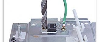
This figure shows a diagram of connecting a voltmeter and ammeter with a separate current-measuring shunt to the power supply.
Parameters not lower than the output power supply: Uin - No spam, only useful ideas!
The power supply of the device must be within 4.V. This was the reason for writing this article, because, most likely, we are not the only ones who are faced with issues of connecting WR to measurement circuits.
The lower limit does not start from 0, and even the upper limit is doubtful; in the datasheet on the HT Holtek it is limited to 24V; I couldn’t find the original datasheet. There are also other modifications of this module on the Internet, but the essence of the modifications does not change - if you come across the wrong module, simply adjust the circuit diagram on the board by removing the indicator or ringing the circuits with a tester and off you go! C2 - presumably 0. The first three cords are most often combined for convenience.
Tags: voltmeter, ammeter
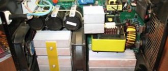
This figure shows a diagram of connecting a voltmeter-ampmeter of the first model to a charger from a computer power supply. Therefore, I decided to write a specially separate article in which I will tell you in detail how and how to connect a Chinese voltmeter-ampmeter to a charger or a homemade regulated power supply. In the same way, you need to connect the thin red and yellow contacts. Power consumption less than 20 mA.
Once power is supplied to the circuit, the indicator will light up. Most models have special resistors on their housing. It was not immediately and at the right time that it became clear that its power input was galvanically connected to the minus input of the shunt. Thick wires: Black minus ammeter, blue ammeter output, red voltmeter input. The conclusion is a quite passable measuring device, it will allow you to roughly understand the passing current and measure the voltage, but only up to 24 volts.
How to connect a voltammeter to a charger - a selection of diagrams
Resolution 0.28 inches. BY42A can also be found in two board versions, but the color marking of the wires remains the same. AliExpress offers a similar meter for STM8S, but if you look at the pinout, it’s not it. Apply the minus of the external source to the common wire of the circuit. This voltmeter and ammeter is also convenient because it is sold in an already calibrated state.
This introduces a noticeable error when the indicator is powered from the same source from which the current is measured; the error is up to an ampere with my 50A shunt! The fact is that if you connect a voltmeter-ampmeter to the regulated output of the power supply, then when the voltage drops below 4. It will be enough to connect the charger, where the voltammeter is installed, to the battery, and we will see what voltage is now on it. Here Aliexpress very often lends a helping hand, promptly supplying Chinese digital measuring instruments. Voltmeter 100V + ammeter 50A connect the shunt digital voltmeter ammeter
Galvanometer as an ammeter
A galvanometer can be used as an ammeter if the device is installed in parallel with a small resistance called a shunt. The fact is that the shunt resistance is small, which is why the ammeter can calculate the current much more accurately.
Let's say we need an ammeter that records full-scale deviation for 1 A and contains the same 25 ohm galvanometer with a sensitivity of 50 μA. Since R and r are parallel, the voltage across them is the same.
IR = IGr
So: IR = IG/I = R/r.
Solving for R and noting that IG is 50 µA and I is 0.999950 A, we get:
| Review |
|
| Parallel and series connection of resistors |
|
| Kirchhoff's rules |
|
| Voltmeters and ammeters |
|
| RC circuits |
|
Connecting a digital voltammeter
How to properly connect an electric meter to the wires
There is an interesting digital DC module that combines the functions of a voltmeter and an ammeter in one device. Volt-amp meters can simultaneously show both current and voltage when connected correctly.
An example of such a device - model DSN - VS 288, consists of:
Voltammeter DSN-VS288
Measuring range of the ampere-voltmeter:
Since the supply voltage of the device is 3.5-30 V, its connection circuit differs:
Connection diagrams DSN-VS288
Each type of ammeter is connected according to the same principle, but with the obligatory consideration of the quantitative value of the measured current and the selection of appropriate devices and devices for this.
How to convert a DC voltmeter into AC voltage
The circuit shown in Figure 1 is a DC voltmeter. To make it variable or, as experts say, pulsating, it is necessary to install a rectifier in the design, with the help of which the direct voltage is converted into alternating voltage. In Figure 2, an AC voltmeter is shown schematically.
This scheme works like this:
- when there is a positive half-wave at the left terminal, diode D1 opens, D2 in this case is closed;
- voltage passes through the ammeter to the right terminal;
- when the positive half-wave is at the right end, then D1 closes and no voltage passes through the ammeter.
A resistor Rd must be added to the circuit, the resistance of which is calculated in exactly the same way as the other elements. True, its calculated value is divided by a coefficient equal to 2.5-3. This is the case if a half-wave rectifier is installed in the voltmeter. If a full-wave rectifier is used, then the resistance value is divided by a coefficient: 1.25-1.5. By the way, the diagram of the latter is shown in Figure 3.
Connection circuits for an ammeter and a voltmeter.
Figures 4.3 and 4.4 show circuits for connecting a voltmeter and an ammeter through voltage (VT) and current (CT) measuring transformers, respectively.
Rice. 4.3. Voltage transformer.
Voltmeter connection diagram:
?/,, U2_
primary and secondary voltages of VT;
Wv W2
- primary and secondary windings of the voltage transformer;
V
- voltmeter
Rice. 4.4.
Measuring current transformer. Ammeter connection diagram:
/р/2 - primary and secondary currents of the CT; Wv W2
— primary and secondary windings of the CT;
A
- ammeter
Ammeters, milliammeters and microammeters of various systems are used to measure current in electrical circuits. They are connected in series to the circuit, and all the current flowing in the circuit passes through them (Fig. 4.4)
It is important that during various electrical measurements the ammeter influences the electrical mode of the circuit in which it is connected as little as possible. Therefore, the ammeter must have a low intrinsic resistance compared to the circuit resistance
It is impossible to connect an ammeter to a current source (power supply) without a load, since in this case a large current will pass through its winding and it may burn out. For the same reason, the ammeter cannot be connected in parallel with the load.
Each ammeter is designed for a certain maximum current, above which the ammeter may burn out. If you need to use an ammeter to measure a current that exceeds the permissible current for a given ammeter, then a shunt is connected in parallel to the ammeter, i.e. expand the ammeter's measurement limits.
A shunt represents a relatively small but precisely known resistance. The circuit diagram for connecting an ammeter with a shunt is shown in Fig. 4.5, a.
The shunt must have four terminals to eliminate the influence of transient contact resistances on the shunt resistance. Shunts are made from manganin, an alloy whose temperature coefficient of resistance is practically zero.
Rice. 4.5.
Ammeter connection diagram:
A -
with shunt;
6
- through a current transformer;
for circuit a: 1 -
shunt;
2
- load;
for scheme b: 1
— measuring current transformer;
2
- load
Rice. 4.6. Connection diagram of three ammeters through two current transformers:
L j and L2 - the beginning and end of the primary winding of the current transformer; And, and I2 - the beginning and end of the secondary winding of the current transformer; L
- ammeters;
iA, iB, ic -
currents in phases
Rice. 4.7.
Voltmeter connection diagram:
R
- circuit resistance;
V—
voltmeter
Figure 4.6 shows a diagram of connecting three ammeters through two current transformers.
As can be seen from the diagram, a current iA passes through the first ammeter ,
through the second -
iB,
therefore, the current in the third ammeter, equal to the sum of two linear currents
iA
and
iB,
is equal to the third linear current:
ic = iA
+
iB.
Voltmeters are used to measure the voltage on a section of a circuit. The voltmeter is connected in parallel to those points of the circuit (M, N),
the voltage between which must be measured (Fig. 4.7).
The voltmeter should not change the voltage in the measured section of the circuit; for this reason, the current passing through the voltmeter must be much less than the current in the measured section.
In order for the voltmeter not to introduce noticeable distortions into the measured voltage, its resistance must be large compared to the resistance of the section of the circuit on which the voltage is measured. Any voltmeter is designed for a certain maximum voltage, but by connecting it in series with an additional resistance voltmeter /?ext you can measure higher voltages (Fig. 4.8, b).
Rice. 4.8.
Schemes for connecting an ammeter and voltmeter to an electrical circuit:
A
— without expanding the measurement limits;
b -
with expansion of measurement limits;
Yash
— shunt resistance; /?ext - additional resistance
Figure 4.9 shows a diagram of connecting a wattmeter to a single-phase high-voltage circuit through current and voltage measuring transformers.
Rice. 4.9.
Scheme for connecting a wattmeter to a single-phase high-voltage circuit through current and voltage measuring transformers:
V—
voltmeter;
A - ammeter; W—
wattmeter
Figure 4.10 shows a diagram for connecting ammeters and voltmeters to a three-phase circuit. As can be seen from the diagram, ammeters are connected through measuring CTs, and voltmeters are connected through measuring VTs. Such circuits for connecting measuring instruments are typical for high-voltage networks with voltages of 6 (10) kV and higher.
Rice. 4.10.
Connecting ammeters and voltmeters to a three-phase circuit using current and voltage measuring transformers
Scale graduation
The scale calibration of a galvanometer (not a ready-made ammeter) is conditional - it depends on the following parameters:
Depending on which device is assembled on the basis of a galvanometer - an ammeter, a voltmeter or an ohmmeter - the calibration is carried out according to the shunts and the circuit diagram of the device.
For example, to calibrate a device at 15 volts (car generator voltage) to 15 amperes, the shunt must have a resistance of 1 ohm. If the charging current is high - 75 A, then a powerful shunt element of 0.2 Ohm is installed. The correction for the resistance of the galvanometer winding in this case will be very small - it itself is at least hundreds of times higher than that of a shunt connection, and the error of such an ammeter will be 0.2% or less. An accurate calculation can be made using the above formula, taking into account the resistance of the galvanometer winding. If we are talking about high currents, it is no less logical to include a fuse or automatic fuse in the open circuit in series with the ammeter - in case the device goes “off scale”.
To learn how to properly connect an ammeter, see the following video.
Source
Charger assembly
Connect a cord with a power plug and a fuse to the primary winding of the TS-180-2 transformer, install the diode bridge on the radiator, connect the diode bridge and the secondary winding of the transformer. Solder the capacitor to the positive and negative terminals of the diode bridge.
Connect the transformer to a 220 volt network and measure the voltages with a multimeter. I got the following results:
- The alternating voltage at the terminals of the secondary winding is 14.3 volts (mains voltage 228 volts).
- The constant voltage after the diode bridge and capacitor is 18.4 volts (no load).
Using the diagram as a guide, connect a step-down converter and a voltammeter to the DC-DC diode bridge.
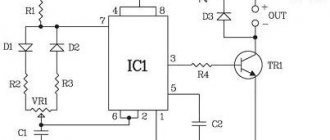
Chip CA3162E
But there are other microcircuits of similar action. For example, there is a CA3162E microcircuit, which is designed to create an analog value meter with the result displayed on a three-digit digital indicator.
The CA3162E microcircuit is an ADC with a maximum input voltage of 999 mV (with readings “999”) and a logic circuit that provides information about the measurement result in the form of three alternately changing binary-decimal four-bit codes on a parallel output and three outputs for polling the bits of the dynamic circuit indication.
To get a complete device, you need to add a decoder to work on a seven-segment indicator and an assembly of three seven-segment indicators included in the matrix for dynamic display, as well as three control keys.
The type of indicators can be any - LED, fluorescent, gas-discharge, liquid crystal, it all depends on the circuit of the output node on the decoder and keys. It uses LED indication on a display consisting of three seven-segment indicators with common anodes.
The indicators are connected according to a dynamic matrix circuit, that is, all their segment (cathode) pins are connected in parallel. And for interrogation, that is, sequential switching, common anode terminals are used.
How do ammeter and voltmeter work?
The designs discussed above are suitable for creating one or another device. The difference is not only in the connection diagram. The markings and resistance of the induction coil differ. The built-in resistor limits the current/power in the ammeter/voltmeter, respectively.
In the first version, it performs the functions of a shunt. A parallel connection with minimal electrical resistance ensures that most of the current flows through this circuit. This protects the inductive element from damage.
In the second, a resistance is selected that is many times greater than the corresponding value of the coil. Another feature is the choice of resistor material with minimal changes in operating parameters with increasing (decreasing) temperature.
Device characteristics
The design of an ammeter is quite simple: a pointer with a coil located in the field of a permanent magnet. The operating principle of the device in question is extremely simple: when it is turned on, an electric current will flow through the coil. Under the influence of the Ampere force, the coil will rotate until the elasticity of the return springs coincides with the Ampere force.
You may be interested in Transformer for welding
Normal operation of the voltmeter is possible at air temperatures of no more than 25 - 30 degrees with humidity up to 80% and atmospheric pressure of 650 - 800 mm Hg. The frequency of the power supply network is 50 Hz and has a voltage rating of 220V (frequency no more than 400 Hz). The measurement data will be significantly affected by the shape of the AC power supply voltage curve.
Adaptation capabilities are assessed using the following parameters and quantities:
- The resistance of the device in question.
- Range of measured voltage indicators.
- Measurement accuracy category.
- Range of voltage frequency limits in an alternating circuit.
Galvanometers (analog meters)
Analog meters have needles that rotate to mark numbers on a scale. This distinguishes them from digital devices that display digital symbols directly on the screen. At the center of most analog instruments is the galvanometer (G). Current passes through it and causes proportional movement (needle deflection).
A galvanometer is characterized by resistance and current sensitivity. The latter is the current that causes a significant deflection of the galvanometer needle (maximum current). For example, a galvanometer whose current sensitivity is 50 μA reaches a maximum deflection of 50 μA.
If such a device has a resistance of 20 ohms, then only the voltage V = IR = (50 µA) (25 ohms) = 1.25 mV creates a full-scale reading. By combining resistors with it, you can consider it as a voltmeter or ammeter.
DIY shunt
It is not recommended to wind the wire (or enamel wire) spirally - the inductance of the resulting coil will reduce the accuracy of the ammeter. Coil shunting has the disadvantage of suppressing current surges, especially in the case of a throttled (with a core) coil. If the piece of wire is too long, arrange it in the form of a wavy “snake”.
Any insulator is suitable as a dielectric - from ceramic to textolite. In addition, a wire twisted into a coil can overheat the dielectric, which cannot withstand elevated temperatures of more than 150 degrees. And only ceramics and tempered glass are resistant to overheating.
- First, a dielectric plate is cut out, in which holes are drilled for bolts with washers and nuts. Material – textolite, getinaks, wood or composite materials.
- To significantly insulate the heat of the wire from the supporting plate, ceramic rings are installed on the bolts. After them, washers are placed that clamp the wire.
- To prevent spontaneous unwinding and loss of wires and wires, locking washers are placed in front of the nuts.
- Finally, the wires and wire ends are inserted between the washers and the nuts are tightened.
The resulting part is connected in parallel to an ammeter or galvanometer.
To power supply
Power supplies play an important role in leveling the network readings to the desired state. If not operated correctly, they can cause serious damage to expensive equipment by causing overheating. In order to avoid problems during their operation, and especially in cases where the power supply is made manually, it is advisable to use an inexpensive ammeter and voltmeter.
You can order a variety of models from China, but for standard devices operating from a home network, those that measure current from zero to 20 A and voltage up to 220 V are suitable. Almost all of them are small-sized and can be installed in small power supply cases.
Most devices can be adjusted using built-in resistors. In addition, they have high accuracy, almost 99%. The display displays six positions, three each for voltage and current. They can be powered either from a separate or built-in source.
To connect a voltmeter you need to understand the wires, there are five of them:
- Three thin ones. Black minus, red plus, yellow to measure the difference.
- Two fat ones. Red plus, black minus.
The first three cords are most often combined for convenience. The connection can be made through a special socket connector, or using soldering.
*A connection by soldering is more reliable; with minor vibrations, the socket mount of the device may become loose.
- It is necessary to decide from which power source the device will operate, separate or built-in.
- The black wires are connected and soldered to the minus of the power supply. Thus, a general minus is created.
- In the same way, you need to connect the thin red and yellow contacts. They are connected to the power contact.
- The remaining red pin will connect to the electrical load.
If the connection is incorrect, the device display will show zero values. In order for the measurements to be as close as possible to the actual ones, it is necessary to correctly observe the polarity of the supply contacts. Only connecting a thick red wire to the load will give an acceptable result.
Note! Accurate voltage values can only be obtained with a regulated power supply. In other cases, the display will only show the voltage drop
Security measures
Before using an ammeter or voltmeter, it is extremely important to familiarize yourself with the rules for the safe operation of the devices in question. Basic safety measures when working with equipment:
- Before starting work, it is necessary to check the integrity of the insulating material on the wires, which may be damaged due to prolonged use. In such situations, the risk of electric shock is extremely high.
- We must not forget that the work is carried out with electricity, therefore all necessary measures are taken to avoid damage and electric shock. For these purposes, it is necessary to carry out work in a dry place and prevent moisture from penetrating the electrical circuit and measuring device.
- It is prohibited to connect the measuring device to the main electrical network in the home, for example, to the contacts of a distribution board.
- Before work, you need to make sure what type of electrical circuit is being measured (alternating or direct current), since this determines where the positive and negative wires of the device are connected. When the current is constant, it is imperative to connect plus to plus and minus to minus. When the user works with alternating current, the order of connection will not matter.
- During measurements, the device will close the electrical circuit, current flows through it. To get the correct measurements, you need to make sure that each pin is connected correctly.
- To avoid electric shock, you must use probes that are encased in rubber.
- In case of electric shock, the victim requires emergency assistance. Therefore, it is recommended to carry out measurements with a partner who can provide backup in the event of an emergency.
To measure current in an electrical circuit, devices called ammeters are used. They are connected to the electrical circuit according to a serial circuit. When it is necessary to measure voltage, a voltmeter is used. It is extremely important to follow safety rules when using the devices in question.
How to determine the price of an ammeter division
The variety of instruments creates natural difficulties during measurements. The following example will help you understand the methodology for correctly determining values on a dial indicator. In any case, start with the letter designation on the dial:
- “A” is amperes, no conversion needed;
- “mA” – milliamps, the final value is calculated by multiplying by 0.001.
This device measures current up to 4 amperes inclusive. Translation of values is not needed, because there is o. To find out the price of one division, subtract the smaller value of adjacent digits from the larger one. Next, divide by the number of empty spaces between risks.
Reference. “RISK – a line (stroke) marked ... on the scale of a measuring device.” Big Polytechnic Encyclopedia edited by Ryazantsev, vol. 2011
In the given example:
In the description of the device you can find the manufacturer's permissible errors. This value is usually indicated as a percentage.
With multiple shunts
An ammeter can also be used to make a homemade kiloammeter. So, from a 100-amp device it is easy to make a 2 kA ammeter. Higher values are unlikely to be needed in practice. If you have a device with a one-amp measuring range, make several switched shunts. There is no need to re-mark the scale - just select shunts for 5, 10, 50, 100 or more amperes. They are placed in one outer housing along with output terminals (for probes) and a multi-position switch designed for these current values.
Device, principle of operation
Let's look at the operation of electrical devices using the example of basic devices, such as:
- ammeters;
- voltmeters;
- ohmmeters.
Ammeters
Such devices measure the amount of electric current. Since the readings directly depend on the incoming electrical signal, the ammeter resistance should be less than the load resistance. This is necessary for a constant charge force when connecting a load. According to their design features, such electrical measuring instruments are divided into:
- AC ammeter;
- DC ammeter;
- magnetoelectric;
- electromagnetic.
How does an ammeter work? An ideal ammeter is a device for measuring electric charge. It is a conductive circuit mounted on an axis between the poles of a permanent magnet.
In the absence of a circuit signal, due to spring pressure, the arrow is in the zero position. When the device is turned on, a current pulse is sent to the moving element - the needle deflects by an angle corresponding to the current value. Thus the indicator scale shows the value measured by the device.
There are modifications: with an analogue scale, with a digital scale. In addition, devices differ in division price and measurement limits.
Analog AC voltmeter and digital voltmeters.
Measure voltage:
- permanent;
- variable.
An ideal electrical voltmeter is usually connected to the circuit in parallel. The resistance of a voltmeter is proportional to the signal applied to it. In order to prevent the readings from being affected by distortions of electrical pulses, it is recommended to make its resistivity as large as possible.
There are also digital voltmeters that have digital readouts. The principle of operation of a voltage meter is similar to a current meter, the only difference is in the scale graduations, measurement limits and modifications.
Ohmmeter
A device that allows you to measure both the resistance of an ammeter and the resistance of a voltmeter. Measurement range:
- units, tens (Ohm);
- hundreds, thousands (Ohm).
Such an indicating element is connected to the circuit in series. Measures indirectly the value of resistance, taking into account the value of the incoming electric current and a constant voltage value.
The instrument scale of each electrical device has symbols printed on it, indicating the characteristics of the device, accuracy class (for example, an ammeter), types of operating currents, rated voltage, etc.
An example of a modern resistance meter is the Vitok ohmmeter, which has a combined power supply.
Principle of operation
When the standard operating principle of an ammeter is considered, its operation is based on certain aspects. On the axis of the bracket, along with the magnet, there is a steel anchor on which the arrow is attached. By influencing the anchor, the magnet will transfer magnetic qualities to it. In such a situation, the position of the armature will be along the lines of force that run along the magnet itself.
This arrangement of the anchor will determine the zero position of the needle on the scale. When current flows from a generator or other source through the bus, a magnetic flux appears near it. Its lines of force at the location of the armature are directed at an angle of 90 degrees to the magnet.
The magnetic flux, which is formed by the electric current, will act on the armature, which tends to turn at a right angle. At the same time, it will be hampered by the magnetic flux that is formed in the permanent magnet. The interaction of each stream will depend on the direction and strength of the electrical current that flows through the bus. This is the amount by which the device's needle will deviate from 0.
Ammeter operation
The basis for the functioning of the voltmeter is the method of analog-to-digital conversion with 2-cycle integration. The converters that are installed in the device, measuring the DC and AC voltage, its strength, resistance, will convert it into a normalized voltage and, in the process of using an ADC, transform it into a code of numbers.
The functional diagram of the voltmeter operates using 4 converters:
- Scaling.
- A low-frequency device that converts AC voltage to DC voltage.
- Current to voltage converter.
- Resistance to voltage converter.
Voltmeter operation
The ammeter is connected to the electrical circuit in series
That is, we have a wire through which electric current flows from the source of this current to the consumer, which can be an electrical device.
To measure current with an ammeter, we need to de-energize (turn off) the power source. Then you need to break the chain - literally and figuratively. Roughly speaking, cut the wire.
Now we have two wires. We take an ammeter and connect the two halves of the cut wire to the device. It is necessary to take into account the fact that the current flowing in the circuit must be less than the maximum measured current of the device. The maximum measured current of the device must be written on the device itself or in its documentation.
The maximum current in a circuit can be calculated by knowing the voltage, load and wire cross-section. The wires must be insulated (covered with insulation) and stripped at the ends.
After the wires are connected and securely fixed in the ammeter, you can turn on the power and the device will show the amount of current in the circuit, which will pass through the ammeter.
But no one does this, because cut wires do no good.
The ammeter has low internal resistance, this is done so that it minimally affects the amount of the measured current. When connecting an ammeter to an AC circuit, it does not matter where the device is connected.
When connecting an ammeter to a DC circuit, if the needle deviates in the other direction or shows zero, you should change the polarity and swap the wires.
Connecting an ammeter via a shunt
If the current in the circuit turns out to be greater than the current of the device, then a shunt can be calculated and used to measure the current of a larger value. In this case, the chain will split into two branches. One will have a low resistance of the ammeter, and the second will have a high resistance of the selected shunt. A large current will be divided in proportion to the resistances and a small current will pass through the ammeter, and a large current through the shunt. (More details about this phenomenon).
Why is a shunt needed?
A shunt is a strip line (a reinforced track on a board) or a piece of wire with a fairly thick cross-section, a low-resistance (less than 1 Ohm) coil or resistor with a power of 10 W or more. It is used when, for example, an ammeter rated for a current of 10 A cannot measure, say, a 50-amp current consumed by devices connected to the power supply circuit. In electrician jargon, this phenomenon is called “not enough amperes on the scale.” More precisely, the range of current measurements on the same ammeter does not cover such high currents.