Types of mandrel pipe bending machines
According to the control method, a mandrel pipe bending machine can be semi-automatic or automatic.
If it is a semi-automatic device, then it will have to be operated partially manually, that is, it will require physical labor. But the operation of automatic equipment is regulated by a CNC machine with a built-in computer (more details: “Types of CNC pipe benders, advantages and rules of use”). Data about the bending pattern and its numerical indicators are entered there, so one worker is sufficient to control the functioning of the apparatus.
Although the pipe configuration can be very different, the bend radius of the pipe should not be greater than twice the radius of the pipe. At the same time, the reliability and tightness of a structure in which fitting connections are used instead of bending pipes will be significantly lower.
Varieties of design of a pipe bending machine with a mandrel:
- Crossbow - equipped with a T-shaped frame. It consists of a pipe holder and a movable arm mounted perpendicularly. A hand tool of this type is capable of bending a pipe at an angle of up to 180º. And it is usually used for assembling heating and plumbing systems.
- Hydraulic type - there are manual and stationary models. Using a manual mandrel pipe bender, you can shape pipes with a small cross-section, but stationary models are used to work with products with a diameter of up to 100 mm in industrial production conditions. You can bend the workpiece on such a machine up to 90º.
- Powered equipment. Pipe benders of this type are widely used in various spheres of life, since they have fully automatic control and can give pipes a wide variety of configurations with high quality and accuracy.
Bending a pipe with a mandrel can be performed according to various patterns. If crossbow or hydraulic pipe benders are used for work, the result is a product that exactly matches the specified parameters.
Equipment with roller mechanisms bends pipes by gradually winding parts onto rollers. However, machines of this type are only stationary. And if we are talking about conveyor production, then pipe benders with power supply are used.
Pipe for heat exchanger.
In the production of heat exchangers for itermic convectors, seamless pipes (seamless) with a diameter of 16 mm and a thickness of 0.5 mm from the following European manufacturers are used: Cupori, Halcor, Wieland.
Aluminum lamella 50 mm high, 100 mm long, made of aluminum foil 0.35 mm thick. More frequent corrugation of the lamella increases its heat transfer area.
How to lubricate the parts being processed
Spindle oil
Spindle oil with the addition of oleic acid is used as a lubricant. The composition has good performance characteristics, such as fluidity and penetrating ability, necessary for contacting surfaces. Oleic acid is a type of surfactant and, when exposed to a metal coating, reduces the hardness of the metal and the frictional force that occurs when the mandrel and the surface of the hole come into contact.
The heating temperature of the contacting bodies decreases, as a result, the treated coating is less rough and no growths remain on the edge of the deforming mandrel.
The amount of acid in the lubricant should not exceed 10 percent. Excellent quality characteristics are achieved precisely at this concentration. Exceeding this figure will be inappropriate and will not give a better effect.
The method of burnishing using shock pulses is the most advanced and widespread, compared to other schemes for deforming the internal surface of a part.
Heat exchanger assembly.
The lamellas are placed on a copper pipe, then burnishing occurs - moving a rotating steel ball under the pressure of a metal rod along the entire length of the pipe. A pipe with a diameter of 15.88 mm after burnishing becomes 16.65 mm. This method is necessary in the production of heat exchangers because it removes the air plug between the pipe and the aluminum lamella, ensuring 100% heat transfer contact.
Heat exchanger after burnishing.
After burnishing, a cassette is obtained, then a roll and fittings are soldered to it and it becomes a heat exchanger
Do-it-yourself barrel mandrel
The operation of mechanical components of machines is accompanied by a serious load on the surface of the parts, especially with regard to various holes.
The upper contact layer of metal takes on the lion's share of mechanical influences and forces, preventing a destructive effect on the inner layers. The stronger this outer layer is, the higher the overall wear resistance of the product will be.
To artificially strengthen the surface of the holes, a technological technique such as mandreling the holes is used.
In mechanical engineering, mandreling is the use of a process of strengthening the surface of a hole by calibrating or drawing a deforming one. In addition, burnishing allows for shaping or finishing of the hole bore. The layer that is strengthened can be of different thicknesses, it depends on the magnitude of the tension.
Purpose and scope of application of burnishing
As briefly mentioned above, burnishing is necessary to strengthen the surface of the hole shafts, giving them greater strength, thus increasing the wear resistance of the product.
All this is accomplished due to the ability to plastically deform the metal throughout the contact zone using a mandrel. There are two types of mandrels: sliding and rolling.
Most often, the process occurs when the workpiece is cold.
When the mandrel tool moves along the barrel with a certain level of tension, other problems are solved along with strengthening the walls:
- adjusting the diameter of the hole to the required parameters, the trunks of rectangular holes to the required dimensions;
- getting rid of irregularities and any roughness that were caused by the previous processing of the trunk;
- the ability to form a certain cross-sectional shape, for example, to create slots, grooves or an original pattern on the inner surface.
Mandrelization is used not only in civil engineering, but also in weapons production. With its help, gun barrels of tanks and other vehicles are strengthened and used in the manufacture of cartridges.
When it is planned to apply mandrel to a particular hole, it is important that the mandrel has a diameter larger than the cross-section of the hole's barrel by the tension thickness. All this is calculated very accurately so that there is no rupture of the workpiece
Varieties
The types of mandrelization mean the free and non-free process of carrying out the operation. When the mandrel is free, the product, namely its surface, is not limited in the possibility of deformation. This type of process is acceptable for large-scale work with electric-welded pipes or for seamless casting, where the thickness of the barrel wall is determined as an average value.
Free mandrel is not suitable for workpieces such as pipes with thin barrel walls. Here, non-free blowing is used, which avoids the following consequences:
- axial displacement of the workpiece;
- decreased stability along the direction of the trunk;
- smoothing metal of insufficient quality.
To implement the non-free mandrel operation, the part is secured in special cages of a rigid and elastic structure before passing through the mandrel.
The use of any of the burnishing methods requires the use of lubricants to reduce friction, speed up the processing process, and avoid damage to the workpiece or tool.
Varieties and technological features
According to the technological features of implementation, mandrelization can be free or non-free. In free mandrelizing, which is predominantly used for seamless and electric-welded pipes with walls of medium thickness, the amount of deformation of the outer surfaces of the processed products is not specified.
Depending on the method of fastening the part, the mandrel can be free or in cages
Internal holes in thin-walled tubular products are predominantly subjected to non-free burnishing. When performing such a technological operation, the absence of the following processing consequences is guaranteed:
- curvature of the axis of the workpiece being processed;
- reducing the stability of the workpiece in its longitudinal direction;
- the presence of surface areas whose smoothing was performed poorly.
To ensure such a high quality of processing, during non-free mandrel the product is secured in special holders that are characterized by high rigidity and elasticity. Often this operation is combined with cold reduction, during which the diameter of the hole being machined and the tool are reduced under the influence of low temperatures.
Options for the combined burnishing-reduction process
Burning parameters
The process of workpiece deformation is accompanied by the following indicators:
- ordinary and relative interference;
- the speed of the deformation process;
- the force with which the deformation is performed;
- relative deformation.
Preference is the main indicator of burnishing of the hole being machined. It is determined by the difference between the diameter of the hole in the part and the cross-sectional size of the tool used. If the parameter value is too large, then further processing of the product will be impractical. The coating may end up with an insufficient degree of roughness.
When choosing the tension, the strength and ductility of the workpiece are taken into account. The value of the relative mandrel interference is obtained by dividing the hole size by the normal interference.
To ensure that the result of processing the product is normal, the tolerance on the hole size of the part is compared with the amount of interference. Half of this value should exceed the hole size tolerance.
The mandrel force is the force that the mandrel creates when acting on the walls of a pipe or liner in both radial and axial directions. When the mandrel exerts radial pressure on the hole, the cross-sectional area of the pipe will increase. If the tool exerts force in the direction of the axis, small roughness and irregularities on the inner wall of the pipe are removed.
Relative deformation shows the change in the outer diameter of the workpiece as a result of burnishing. This indicator is measured as a percentage.
Main settings
Experts are guided by the following burnishing parameters:
- normal and relative interference;
- execution speed;
- execution strength;
- relative deformation.
For normal burnishing, the tolerance on the dimensions of the hole being machined should be several times less than half the interference
The interference, which is one of the main parameters of mandrel, is the difference between the diameters of the hole being machined and the cross-sectional size of the tool used. If this indicator is too high, then during the processing it will not be possible to form a surface with the required level of roughness. When choosing this parameter, you should take into account both the degree of plasticity of the product being processed and its strength characteristics. The relative mandrel interference is understood as the value obtained by the ratio of the size of the machined or unprocessed hole to the value of the usual interference.
When mandrating, the force applied to the tool is divided into axial and radial components
The force with which mandrel is performed refers to the forces that the tool exerts on the walls of the hole in the radial and axial directions. With the help of the force exerted by the tool in the radial direction, the cross-section of the hole being processed increases, and the force created by the mandrel in the direction of the axis of the workpiece makes it possible to remove the smallest irregularities from its inner surface.
Relative deformation, measured as a percentage, makes it possible to determine how much the outer diameter of the workpiece has changed during mandreling.
Cylindrical leather punches
Professional tools that are used for punching holes in the leather industry or in the saddlery industry, of course, differ from household tools both in their quality characteristics and the strength of the materials used, but a homemade option can also be good.
If you need to make a hole of a large diameter (for eyelets, rivets), you should use a hole punch in the shape of a metal pipe with a sharp edge. It may have a rubber or plastic handle, and you can additionally equip it with a service hole to remove knocked-out leather circles. By choosing different tube diameters from 1.5 to 18.8 millimeters, you can make holes of different sizes.
To make a hole on a leather product, you will need to lay it on a flat, hard surface, make a mark, place the punch vertically, and press the tube with your hand, turning it slightly. As a result, you will get a neat, smooth-edged hole that your cylindrical punch made.
Profilometer
Profilometers for workshop control of surface roughness type 240 (GOST 9504 - 60) are intended for grades 6 - 12.
Profilometers immediately display on the indicator the root mean square value of surface roughness in microns.
Profilometers are very convenient to use.
The profilometer allows you to determine the cleanliness of the surface in holes with a diameter of 8–5 mm. With additional devices, the device can also record a profilogram. The small profilometer sensor is designed for measuring small parts, in particular cylindrical surfaces with a diameter of 8 mm. In addition to the recorder, the device is supplied with an attachment for assessing surface cleanliness using the parameter – smoothing depth (G) with measurement ranges: 0 – 1 25; 0 – 6 25 and 0 – 12 5 microns. The device is designed for use during processing. The signal light located on the front panel lights up until the G value reaches the value preset on the device.
The profilometer must be designed to measure surfaces with a regular profile of any shape, as well as surfaces whose deviations of irregularities from the center line can be considered as a stationary random process. Based on Fourier series expansions, it is possible to impose certain frequency requirements on the measuring path of probe instruments to ensure correct reproduction of the measured Process or input function.
Kiselev's profilometer, like Abbott's profilometer, is an electromagnetic device in which a coil, rigidly connected to a probing diamond needle, moves in the field of a permanent magnet. When you feel surface irregularities in the turns of the coil, a current is excited, which flows into the integrating circuit and, after amplification, to a pointer device, on which the value of the average square deviation of the heights of the irregularities is measured.
The profilometer shows the numerical value of the measured roughness parameter.
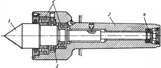
Profilometers of this type use transducers made of long plates of Rochelle salt that work in bending (Fig. The needle 1 is pressed under the influence of its own weight of the moving part 2 of the transducer to the test surface of the part 3, installed either on the plate 4 or on the table 5, depending on the size of the part The moving part with the probing needle makes a reciprocating movement in the direction of arrow A. The drive 6 with the moving part 2 can move along the guide column of the rack 7 in the vertical direction, occupying a position determined by the dimensions of the part being tested.
Profilometers are used to assess surface cleanliness within the 5th – 12th class of cleanliness. Surface cleanliness grades 10–14 are assessed using Linnik microinterferometers.
The profilometer is not applicable in this case, since it scratches the surface of the impression and distorts the shape of the irregularities.
Profilometers and profilographs are used for laboratory testing of the cleanliness of the treated surface.
| Roughness designation when all surfaces have the same roughness.| Designation of roughness when some surfaces remain in the delivered condition.| Designation of the same roughness for some surfaces. |
Profilometers are designed to directly display the arithmetic mean deviation of the surface profile Ra. Profilographs record the surface profile in the form of a profilogram. In Fig. 36, a shows a profilograph-profilometer, and in Fig. 36, b - the principle of operation of this probe device.
The 253 profilometer has a similar design and technical characteristics, but instead of an inductive sensor it uses a mechanotron. The high sensitivity of the mechatron made it possible to significantly simplify the electrical circuit of the device.
A profilometer is used to examine a surface by probing with a needle. The vibrations of the needle that occur when moving excite an electric current in the coil to which the needle is connected. The current strength is proportional to the speed of the needle. Through a chain of amplifiers, the profilometer is connected to an oscilloscope, on the screen of which both vertical and horizontal movements of the needle can be observed in an enlarged form.
Roll for heat exchanger.
Kalach has an important component of the heat exchanger. The coolant passing through the roll experiences hydraulic resistance (loss of energy due to friction along the length and loss of energy when changing the shape and cross-section of the channel). Consequently, it is subject to internal abrasive wear, which leads to a decrease in the wall of the roll and its subsequent leakage. Itermic uses 1mm thick Italian kalach without narrowing the section at the bend.
Thickness of the roll.
On average, a roll with a thickness of 0.45 mm is abraded by the coolant in 5 years, so itermic uses a roll with a thickness of 1 mm. This made it possible to provide the plant’s partners with a 10-year guarantee on all heat exchangers. You can download the kalach quality certificate using the link provided.
Fittings for heat exchanger.
Itermic uses heat exchanger fittings with a built-in air vent on the supply and return. And now you don’t have to worry about mixing them up (supply and return), which happens en masse during installation. We noticed a frequently repeated mistake by installers and corrected it.
Soldering the heat exchanger.
When soldering fittings and coils for Itermic heat exchangers, only high-quality solder from the German company VIEGA is used.
All that remains is to solder and the heat exchanger is ready!
Well, now ask your convector supplier! What do they use in the production of convectors? 1) What is the diameter of the pipe, its thickness, brand, suture or seamless? 2) The roll - its thickness, is there a narrowing at the bend? 3) What is the configuration of the aluminum lamella in a standard heat exchanger, 1 row, two pipes, 50 mm by 100 mm? If it is smaller, then the heating surface area is smaller, therefore the heat transfer is lower! 4) What kind of solder is used when soldering rolls and fittings? 5) Does your manufacturer mandrel the heat exchanger? 6) what is the warranty and working pressure? We can answer any question you are interested in! Can your supplier answer these questions???
Any itermic convector can be made with a stainless steel body, with or without drainage, for swimming pools and any places with high humidity.
Calculation of the required punching force
The metal cutting process is characterized by the fact that during this process a rather complex load pattern appears, which is concentrated in the area where the punch, the material being cut and the matrix interact.
The punch is made in such a way that it does not enter the material with its entire end, but only with the outer annular part. The response comes from the matrix. Moreover, the pressure arising in the interaction zone of these three components is distributed unevenly.
In other words, during the cutting process a pair of forces arises that form a circular bending moment. Under its influence, the sheet bends. As a result of this bending, pressure is generated, which affects the punch and the edge of the matrix. In addition, it is necessary to take into account the fact that tangential forces appear under the influence of friction forces. As can be seen from the above, when punching, a non-uniform force field arises. Therefore, when carrying out calculations, a conventional value is used - shear resistance. As a result of the research, the resistance depends not only on the properties of the metal, but also on the level of hardening, the thickness of the cutting, the gaps in the punch/die pair and the speed of the cutting process.
Read also: Industrial oil and 20a application
If you find an error, please select a piece of text and press Ctrl+Enter.
Technology and types of mandrel holes
The operation of mechanical components of machines is accompanied by a serious load on the surface of the parts, especially with regard to various holes. The upper contact layer of metal takes on the lion's share of mechanical influences and forces, preventing a destructive effect on the inner layers. The stronger this outer layer is, the higher the overall wear resistance of the product will be. To artificially strengthen the surface of the holes, a technological technique such as mandreling the holes is used. In mechanical engineering, mandreling is the use of a process of strengthening the surface of a hole by calibrating or drawing a deforming one. In addition, burnishing allows for shaping or finishing of the hole bore. The layer that is strengthened can be of different thicknesses, it depends on the magnitude of the tension.
Burning schemes
There are the following schemes for metal processing of workpieces by mandrel:
- by stretching;
- compression method;
- combined application of tension and compression of the sample.
It is important to choose the right workpiece processing scheme. The circuit will determine the values of the axial stress of the product
Volumetric processing of a part is carried out according to other schemes:
- passive;
- neutral;
- active.
The listed mandrel schemes influence the value of the axial stress and require special mechanisms - movable supports that make it possible to limit the shortening of the part when exposed to the mandrel. As the interference value increases, the degree of roughness of the inner surface of the workpiece will decrease. This technique involves pre-machining the hole before using the mandrel.
Dorns use two types of movement:
- rocking;
- slip.
The tool moves inside the workpiece with a given tension value using lubricant. To improve the processing result and reduce the mandrel force, lubricant is supplied inside the hole towards the movement of the mandrel by spraying.
The device for performing vibration processing of metal products consists of:
- dorn;
- a vibrating support, which allows you to fix the sample on it;
- hydraulic drive;
- piston
Dorn - device Using the device, the internal walls of bushings, liners and cylinders are effectively processed.
Volumetric and surface burnishing
There are two types of mandrelization of trunks and pipes, in which no chips are formed - volumetric or surface. When performing volumetric burnishing, processing is carried out over the entire cross-section of the workpiece. As a result of such a technological operation, performed using a tool equipped with several teeth, it is possible to form a surface whose roughness will be in the range of 0.04–0.63 microns, and the accuracy will correspond to 11 units on the IT scale.
Volumetric burnishing scheme for small diameter holes
Using volumetric mandrel, long holes, pipe blanks or products made in the form of sleeves are processed. This operation, which can be used to make holes of almost any length while maintaining their straightness, is a good alternative to rough boring.
Scheme of processing a part by surface burnishing
When performing surface burnishing, you can obtain an internal surface whose roughness will be in the range of 0.04–0.32 microns, and the accuracy will correspond to 6–9 units. When surface grinding a hole, a hardened layer of metal is created on the inner surface of the hole, so this processing technology can be successfully used as an alternative to such complex operations as:
- grinding;
- honing;
- deployment;
- ironing.
Purpose and technological features
During the operation of any product, including those made of metal, the main load is taken by its outer surface, while the inner layers remain practically untouched. Such a load, in particular, can be thermal effects, as well as external factors leading to corrosion or intense wear of the metal.
The main task that burnishing, which is a method of processing a metal product, solves is to ensure its reliable protection from the above negative factors. Burnishing is an innovative technology, the essence of which is that the inner surface of holes made in metal parts is subjected to plastic deformation in a cold state, due to which a layer is formed on them, characterized by exceptional mechanical characteristics.
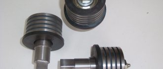
Morn is a tool for burnishing. There are rolling mandrels and sliding mandrels.
Burnishing, performed using a special tool that moves along the inner surface of the hole with a certain degree of tension, allows you to solve the following problems:
- bringing the dimensions of the internal section of the processed product into accordance with the required values;
- elimination of roughness existing on the inner surface of the hole being machined;
- improving the strength characteristics of the metal forming the inner surface of the hole.
If you plan to perform a mandrel, you should keep in mind that the diameter of the hole being machined should always be less than the cross-section of the tool used by the amount of interference.
Examples of parts after burnishing
Why is it necessary?
When operating any parts, devices or devices, it is mainly the outer layers that bear different loads. While the inner layers maintain a constant structure and do not deform. The rule applies to products made of any materials - wood, stone, ceramics, metal.
A negative impact can be exerted not only on the surface of the object, but also on any of its internal elements - holes, cuts, recesses.
Mechanical damage
A strong impact can seriously damage the outer surface of the part, which can lead to cracking (internal holes and various recesses can be damaged). Also, internal elements and surfaces can be damaged naturally. A simple example: Some pipes are used to dispose of heavy industrial debris, which can leave small damage and dents on the inside of the pipe, which will eventually cause the pipe to crack and even collapse.
Corrosion
When water comes into contact with some metals, corrosion can form, which negatively affects the quality of parts. The duration of contact is also of great importance - most modern alloys tolerate short-term exposure to water, whereas with prolonged contact, water can enter into a chemical reaction with the metal, leading to corrosion. In addition to its unpleasant appearance, corrosion negatively affects the hardness of the material, which makes the metal brittle.
Sudden temperature changes
Most modern alloys melt at very high temperatures, but it must be borne in mind that in the event of sudden cooling or heating, some metals become quite brittle. Also, in most cases, only the outer surface is seriously damaged, while the internal structure is preserved. This is especially critical in the case of metal parts with holes of non-standard shape (threaded, with various locking elements).
Aggressive external environment. Many chemically active substances can seriously damage the outer layer of metal upon contact. Examples of chemicals are various alkalis, acids, and explosives. Also, the danger of a particular compound is determined by the degree of toxicity - some chemicals only slightly corrode the outer shell, others create cracks in the material, and so on.
Types of burnishing depending on the fastening of the part
Burnishing can be non-free or free - depending on whether the original parts are fixed on the machine or not during processing.
The free-processing technology is simple, but has a number of disadvantages, and the main disadvantage is that it is not suitable for processing thin-walled products. However, in practice, free technology is very often used when mandrating seamless or electric-welded pipes.
The non-free burnishing technology is more preferable, although less practical, and it is suitable for processing pipes with any wall thickness.
With non-free mandrel, parts are fixed on the machine - this allows you to achieve the following effects:
- The shape of the part is completely preserved, the formation of any random bends, zigzags and irregularities is completely excluded.
- The stability and hardness of the part in all directions is completely preserved (this is especially critical in the case of the longitudinal direction).
- The surface of the part is completely cleaned of various irregularities and defects; non-free mandrel ensures high-quality processing.
To carry out non-free burnishing, the part is secured in a special vise-holder. They must meet a number of requirements - high elasticity, very high rigidity (otherwise the part will slip). If it is necessary to reduce the diameter of pipes, then mandrel burnishing can be combined with cold reduction technology - a similar practice is widely used at factories in all post-Soviet states.
Types of burnishing process
Burnishing processing is classified according to the following criteria:
- type of processing (volumetric and superficial);
- technological features (free and non-free);
- method of influencing the inner surface (tension, compression, combined effect);
- the number and location of teeth on the surface of the tool.
The choice of method and type of such processing depends on the characteristic features of the parts. So, to obtain a high-quality surface of trunks or pipes with an unequally rigid sleeve, a method is used to ensure different effects on individual sections of the inner wall.
To process non-axisymmetric workpieces, mandrels with specially located teeth are used.
Free burnishing is used to treat the surfaces of seamless and electric-welded pipes. The wall thickness can reach medium sizes.
Volumetric and surface burnishing
Volumetric processing is carried out by pressure along the entire internal perimeter. To improve the required quality, multi-tooth mandrels are used. They allow you to achieve high processing accuracy up to class 11. The degree of roughness Ra is equal to 0.63 to 0.04 microns.
Surface burnishing refers to methods of surface plastic deformation.
It allows you to obtain the following accuracy indicators: IT from 6 to 9 units, roughness Ra in the range of 0.32-0.04 microns. Volumetric burnishing is used to process straight-seam welded pipes.
Plastic deformation and sizing
This processing method involves exposing the metal surface to a tool that creates pressure at the point of contact. In this case, a consistent change in the internal structure of the metal occurs. Thanks to the processes of sliding and twinning, the structure of layers changes at the level of the atomic lattice. Such an impact leads not only to a change in the external shape of the part, but also its physical and mechanical properties. With a properly developed method of plastic deformation, it is possible to obtain a surface layer with improved characteristics
This circumstance is especially important when it is impossible to subject a metal part to heat treatment, for example, made from austenitic or ferritic materials
The calibration method is used to process holes in short-length workpieces. For processing, calibrating balls, mandrels, and other calibrating tools are used. In this case, it is pushed through the hole to obtain the expected effect.
In this case, the main parameter for assessing the technological impact is the interference. It is created due to the difference between the internal diameter of the hole and the diameter of the tool. Depending on the problem being solved, calibration is performed with a small or large interference.
When calibrating with a small interference, only the surface layer is affected. Pipes, bushings, and liners with thick walls are subjected to this treatment. The most acceptable ratio of the wall size to the hole radius is more than 0.5.
The use of a large tension leads to an increase in the depth of impact and can extend to the entire thickness of the workpiece. This leads to an increase in the internal diameter, a change in external dimensions, a decrease in the quality of processing, and the occurrence of uneven internal stresses (changes in physical and mechanical properties).
To carry out calibration, it is necessary to carry out high-quality pre-processing. As a result of subsequent calibration, processing accuracy increases by 30%. For example, for steel the accuracy class increases by two units, for bronze by 3, for cast iron by one class.
Shock pulse method
It is based on measuring the parameters of metal deformation after exposure to pulsed mechanical action. At the moment of a short-term impact, ultrasonic vibrations occur, which cause compaction of the surface of the workpiece.
This method is successfully used in the production of long products. For example, mandrel blasting of pipes is carried out using the shock pulse method.
The use of various burnishing methods makes it possible to process the internal surfaces of products of various lengths and arbitrary diameters. As a result of processing, it is possible to obtain a high quality surface layer, without heating and mechanical impact (milling, countersinking, etc.).
Process description
Burnishing is a special material processing technology that allows you to increase the strength of its surfaces. In practice, mandrel drilling of holes (pipes, locking mechanisms) has become widespread. It is carried out using special tools called mandrels - they are a hard working tool (usually with teeth).
During processing, the mandrel moves in the hole with tension, and the outer surface of the material is compacted. Due to this, a special hard layer is formed on the part, which has increased hardness parameters. Please note that burnishing is done cold - processing does not require either complete heating or a local increase in temperature. In addition to improving the physical properties of the surface, the technology solves some auxiliary problems:
- Section diameter correction. During processing, the mandrel tool can cut off the surface layer completely or partially - thanks to this, it is possible to increase the cross-sectional diameter of the hole to the desired values. It is also recommended to use a mandrel only for minor corrections - in case of a serious deviation from the norm, some other processing methods should be used (for example, drilling).
- Elimination of roughness and minor defects. When burnishing, the surface is completely cleaned and leveled. If there were any defects on the part (protrusions, rough elements, small recesses), then the mandrel will cut them off completely during processing. Therefore, burnishing can be used as an auxiliary grinding method.