Types of allowances and tolerances
Depending on the method of processing the part, there are two main types of allowances:
- intermediate or interoperational;
- general.
Intermediate allowances are a layer of metal removed in a separate processing step. The general allowance is a layer removed at all technological stages. This value is calculated by adding intermediate allowances.
Allowance for processing is not a constant value, and this is due to the fact that the dimensions of the workpiece before and after the technological transition can fluctuate within the established tolerance. The machining allowance can be minimum, nominal or maximum. With a minimum allowance, the layer removed is the difference between the smallest size after the operation. The nominal allowance is the difference between the nominal dimensions before and after the technological transition. The maximum allowance is the difference between the smallest dimensions of the surface after the previous transition and the largest dimension after the completion of the current operation.
Mechanical engineering technology is inextricably linked with metrology - the science of measurements, means and methods of ensuring their unity to achieve the required processing accuracy. Two parts connected to each other are called mating. The size by which the connection is made is called the mating size. As an example of mating parts, consider the diameter of the hole in the pulley and the corresponding shaft diameter. The value at which the connection does not occur is called the free size (outer diameter of the shaft).
In order to ensure the interchangeability of parts, the associated quantities must always have accurate values. However, it is not always possible to ensure such accuracy during machining, and sometimes it is simply impractical. Therefore, mechanical engineering uses a method for producing interchangeable parts with so-called approximate accuracy. The essence of this method is that for various operating conditions, parts and assemblies are given permissible deviations from the established dimensions. These deviations do not in any way affect the flawless operation of the elements and are calculated for various operating conditions. They are lined up in a certain scheme, which is called the “System of tolerances and landings”.
Tolerances and fits are the difference between the smallest and largest limiting values of the parameters (mass fraction, weight and dimensions). These parameters are set taking into account the technological requirements for the part. The calculated data for the part is called the nominal size. They are expressed in whole millimeters. The actual dimensions of the part obtained after processing are called the maximum dimensions. In the drawings, these values are indicated by numerical values and are indicated at the nominal size (the upper value is marked at the top of the size record, the lower value at the bottom).
Allowances and tolerances for machining directly affect the productivity and cost of the technological process. The larger these values, the higher the complexity of machining. This leads to increased energy consumption, rapid tool wear and high metal consumption.
One of the ways to reduce allowances is to increase the accuracy of the workpiece and perform preliminary mechanical operations. But this, in turn, requires more accurate and careful installation of parts in fixtures and machines.
The size of the allowance depends on a number of factors:
- accuracy requirements;
- specified roughness of the part;
- configuration and dimensions of the finished product.
The value is influenced by the type of production operation and the error in installing the part in the fixture.
Allowances for finishing turning after roughing
Allowances for finishing turning after roughing
| Shaft diameter, mm | Workpiece length | |||||
| Up to 100 | 100-250 | 250-500 | 500-800 | 800-1200 | 1200-2000 | |
| Allowance for diameter, mm | ||||||
| To 10 | 0,8 | 0,9 | 1,0 | — | — | — |
| Over 10 to 18 | 0,9 | 0,9 | 1,0 | 1,1 | — | — |
| Over 18 to 30 | 0,9 | 1,0 | 1,1 | 1,3 | 1,4 | — |
| Over 30 to 50 | 1,0 | 1,0 | 1,1 | 1,3 | 1,5 | 1,7 |
| Over 50 to 80 | 1,1 | 1,1 | 1,2 | 1,4 | 1,6 | 1,8 |
| Over 80 to 120 | 1,1 | 1,2 | 1,2 | 1,4 | 1,6 | 1,9 |
| Over 120 to 180 | 1,2 | 1,2 | 1,3 | 1,5 | 1,7 | 2,0 |
| Over 180 to 260 | 1,3 | 1,3 | 1,4 | 1,6 | 1,8 | 2,0 |
| Over 260 to 360 | 1,3 | 1,4 | 1,5 | 1,7 | 1,9 | 2,1 |
| Over 360 to 500 | 1,4 | 1,4 | 1,5 | 1,7 | 1,9 | 2,2 |
Note: For conditions of small-scale and single-piece production, the allowance is determined by multiplying the table value by a factor of 1.3, rounding upward to tenths of a mm (Table 1).
For conditions of small-scale and single production, the allowance is determined by multiplying the table value by a factor of 1.2, rounding upward to tenths of a mm (Table 2).
table 2
Allowances for grinding shafts
| Shaft diameter, mm | Type of grinding | Availability of heat treatment | Shaft length, mm | |||||
| Up to 100 | 100-250 | 250-500 | 500-800 | 800-120 | 1200-2000 | |||
| Allowance for diameter, mm | ||||||||
| To 10 | center | raw | 0,2 | 0,2 | 0,3 | — | — | — |
| hardenable | 0,3 | 0,3 | 0,4 | — | — | — | ||
| centerless | raw | 0,2 | 0,2 | 0,2 | — | — | — | |
| hardenable | 0,3 | 0,3 | 0,4 | — | — | — | ||
| Over 10 to 18 | center | raw | 0,2 | 0,3 | 0,3 | 0,3 | — | — |
| hardenable | 0,3 | 0,3 | 0,4 | 0,5 | — | — | ||
| centerless | raw | 0,2 | 0,2 | 0,2 | 0,3 | — | — | |
| hardenable | 0,3 | 0,3 | 0,4 | 0,5 | — | — | ||
| Over 18 to 30 | center | raw | 0,3 | 0,3 | 0,3 | 0,4 | 0,4 | — |
| hardenable | 0,3 | 0,4 | 0,4 | 0,5 | 0,6 | — | ||
| centerless | raw | 0,3 | 0,3 | 0,3 | 0,3 | — | — | |
| hardenable | 0,3 | 0,4 | 0,4 | 0,5 | — | — | ||
| Over 30 to 50 | center | raw | 0,3 | 0,3 | 0,4 | 0,5 | 0,6 | 0,6 |
| hardenable | 0,4 | 0,4 | 0,5 | 0,6 | 0,7 | 0,7 | ||
| centerless | raw | 0,3 | 0,3 | 0,3 | 0,4 | — | — | |
| hardenable | 0,4 | 0,4 | 0,5 | 0,5 | — | — | ||
| Over 50 to 80 | center | raw | 0,3 | 0,4 | 0,4 | 0,5 | 0,6 | 0,7 |
| hardenable | 0,4 | 0,5 | 0,5 | 0,6 | 0,8 | 0,9 | ||
| centerless | raw | 0,3 | 0,3 | 0,3 | 0,4 | — | — | |
| hardenable | 0,4 | 0,5 | 0,5 | 0,6 | — | |||
| Over 80 to 120 | center | raw | 0,4 | 0,4 | 0,5 | 0,5 | 0,6 | 0,7 |
| hardenable | 0,5 | 0,5 | 0,6 | 0,6 | 0,8 | 0,9 | ||
| centerless | raw | 0,4 | 0,4 | 0,4 | 0,5 | — | — | |
| hardenable | 0,5 | 0,5 | 0,6 | 0,7 | — | — | ||
| Over 120 to 180 | center | raw | 0,5 | 0,5 | 0,6 | 0,6 | 0,7 | 0,8 |
| hardenable | 0,5 | 0,6 | 0,7 | 0,8 | 0,9 | 1,0 | ||
| centerless | raw | 0,5 | 0,5 | 0,5 | 0,5 | — | — | |
| hardenable | 0,5 | 0,6 | 0,7 | 0,8 | — | — | ||
| Over 180 to 260 | center | raw | 0,5 | 0,6 | 0,6 | 0,7 | 0,8 | 0,9 |
| hardenable | 0,8 | 0,7 | 0,7 | 0,8 | 0,9 | 1,1 | ||
| Over 260 to 360 | center | raw | 0,6 | 0,6 | 0,7 | 0,7 | 0,8 | 0,9 |
| hardenable | 0,7 | 0,7 | 0,8 | 0,9 | 1,0 | 1,1 | ||
| Over 360 to 500 | center | raw | 0,7 | 0,7 | 0,8 | 0,8 | 0,9 | 1,0 |
| hardenable | 0,8 | 0,8 | 0,9 | 0,9 | 1,0 | 1,2 |
Note for Table 3: In the case of using two cutters, roughing and finishing, an allowance of 0.1 mm is left on the finishing cutter.
Table 3.
Allowances for thin (diamond) turning of shafts
| Processed material | Processable diameter, mm | Allowance for diameter, mm |
| Light alloys | Up to 100 | 0,3 |
| Over 100 | 0,5 | |
| Bronze and cast iron | Up to 100 | 0,3 |
| Over 100 | 0,4 | |
| steel | Up to 100 | 0,2 |
| Over 100 | 0,3 |
Table 4.
Allowances for finishing trimming ends
| Diameter of the workpiece, mm | Total length of the workpiece, mm | |||||
| Before 18 | 18-50 | 50-120 | 120-260 | 260-500 | Over 500 | |
| Allowance per side, mm | ||||||
| Up to 30 | 0,5 | 0,6 | 0,7 | 0,8 | 1,0 | 1,2 |
| 30-50 | 0,5 | 0,6 | 0,7 | 0,8 | 1,0 | 1,2 |
| 50-120 | 0,7 | 0,7 | 0,8 | 1,0 | 1,2 | 1,2 |
| 120-260 | 0,8 | 0,8 | 1,0 | 1,0 | 1,2 | 1,4 |
| 260-500 | 1,0 | 1,0 | 1,2 | 1,2 | 1,4 | 1,5 |
| Over 500 | 1,2 | 1,2 | 1,4 | 1,4 | 1,5 | 1,7 |
Table 5.
Allowances for grinding ends
| Diameter of the workpiece, mm | Total length of the workpiece, mm | |||||
| Before 18 | 18-50 | 50-120 | 120-260 | 260-500 | Over 500 | |
| Allowance per side, mm | ||||||
| Up to 30 | 0,2 | 0,3 | 0,3 | 0,4 | 0,5 | 0,6 |
| 30-50 | 0,3 | 0,3 | 0,4 | 0,4 | 0,5 | 0,6 |
| 50-120 | 0,3 | 0,3 | 0,4 | 0,5 | 0,6 | 0,6 |
| 120-260 | 0,4 | 0,4 | 0,5 | 0,5 | 0,6 | 0,7 |
| 260-500 | 0,5 | 0,5 | 0,5 | 0,6 | 0,7 | 0,7 |
| Over 500 | 0,6 | 0,6 | 0,6 | 0,7 | 0,8 | 0,8 |
Table 6.
Operating allowances for processing holes
(diameter allowance)
| Diameter range, mm | Finish boring the broached hole | After drilling | After countersinking or boring | Clean deployment | ||||
| Countersink. | Rastach. | Chistov. boring | Development | Expand | Rough development | |||
| From 3 to 6 | — | — | — | — | 0,15 | — | 0,15 | 0,05 |
| «6 «10 | — | — | — | — | 0,2 | 0,2 | 0,2 | 0,1 |
| «10 «18 | — | 0,8 | 0,8 | 0,5 | 0,3 | 0,2 | 0,2 | 0,1 |
| «18 «30 | — | 1,2 | 1,2 | 0,8 | 0,3 | 0,3 | 0,2 | 0,1 |
| «30 «50 | 1,3 | 1,5 | 1,5 | 1,0 | 0,3 | 0,3 | 0,2 | 0,1 |
| « 50 «80 | 1,5 | 2,0 | 2,0 | 1,0 | 0,4 | 0,3 | 0,2 | 0,15 |
| « 80 «120 | 1,7 | 2,5 | 2,0 | 1,3 | 0,5 | 0,4 | 0,3 | 0,2 |
| « 120 «180 | 1,7 | — | 2,0 | 1,3 | — | — | — | — |
Table 7.
Operating allowances for grinding holes
| Hole diameter, mm | Availability of surface heat treatment | Length of the hole to be ground, mm | ||||
| Up to 50 | 50-100 | 100-200 | 200-300 | 300-500 | ||
| Allowance for diameter, mm | ||||||
| To 10 | raw | 0,2 | — | — | — | — |
| hardenable | 0,2 | — | — | — | — | |
| St. 10 to 18 | raw | 0,2 | 0,3 | — | — | — |
| hardenable | 0,3 | 0,4 | — | — | — | |
| St. 18 to 38 | raw | 0,3 | 0,3 | 0,4 | — | — |
| hardenable | 0,3 | 0,4 | 0,4 | — | — | |
| St. 30 to 50 | raw | 0,4 | 0,3 | 0,4 | 0,4 | — |
| hardenable | 0,4 | 0,4 | 0,4 | 0,5 | — | |
| St. 50 to 80 | raw | 0,5 | 0,4 | 0,4 | 0,4 | — |
| hardenable | 0,5 | 0,4 | 0,5 | 0,5 | — | |
| St. 80 to 120 | raw | 0,6 | 0,5 | 0,5 | 0,5 | 0,6 |
| hardenable | 0,6 | 0,5 | 0,6 | 0,6 | 0,7 | |
| St. 120 to 180 | raw | 0,6 | 0,6 | 0,6 | 0,6 | 0,6 |
| hardenable | 0,6 | 0,6 | 0,6 | 0,6 | 0,7 | |
| St. 180 to 260 | raw | 0,7 | 0,6 | 0,7 | 0,7 | 0,7 |
| hardenable | 0,7 | 0,7 | 0,7 | 0,7 | 0,8 | |
| St. 260 to 360 | raw | 0,7 | 0,7 | 0,7 | 0,8 | 0,8 |
| hardenable | 0,7 | 0,8 | 0,8 | 0,8 | 0,9 | |
| St. 360 to 500 | raw | 0,8 | 0,8 | 0,8 | 0,8 | 0,8 |
| hardenable | 0,8 | 0,8 | 0,9 | 0,9 | 0,9 |
Note: 1. When processing thin-walled bushings and other parts that are significantly deformed during heat treatment, the tabulated allowance values should be multiplied by a factor of 1.3.
2. For conditions of small-scale and single-piece production, the tabulated allowance values should be multiplied by a factor of 1.3.
Table 8
Operating allowances for broaching round holes
(diameter allowance)
| Pull Hole Length | Diameter of drawn hole, mm | |||
| 10-18 | 18-30 | 30-50 | 50-80 | |
| 6-10 | 0,2 | 0,3 | — | — |
| 10-18 | 0,3 | 0,3 | 0,4 | — |
| 18-30 | 0,4 | 0,4 | 0,5 | 0,6 |
| 30-50 | 0,5 | 0,5 | 0,5 | 0,6 |
| 50-80 | — | 0,5 | 0,6 | 0,7 |
| 80-120 | — | 0,6 | 0,6 | 0,7 |
| 120-180 | — | — | 0,7 | 0,8 |
Table 9
Operating allowances for fine (diamond) boring of holes
| Hole diameter, mm | Processed material | |||||||
| Light alloys | Babbitt | Bronze and cast iron | Steel | |||||
| Nature of processing | ||||||||
| preliminary | will graduate | preliminary | will graduate | preliminary | will graduate | preliminary | will graduate | |
| Allowance for diameter, mm | ||||||||
| Up to 30 | 0,2 | 0,1 | 0,3 | 0,1 | 0,2 | 0,1 | 0,2 | 0,1 |
| 30-50 | 0,3 | 0,1 | 0,4 | 0,1 | 0,3 | 0,1 | 0,2 | 0,1 |
| 50-80 | 0,4 | 0,1 | 0,5 | 0,1 | 0,3 | 0,1 | 0,2 | 0,1 |
| 80-120 | 0,4 | 0,1 | 0,5 | 0,1 | 0,3 | 0,1 | 0,3 | 0,1 |
| 120-180 | 0,5 | 0,1 | 0,6 | 0,2 | 0,4 | 0,1 | 0,3 | 0,1 |
| 180-260 | 0,5 | 0,1 | 0,6 | 0,2 | 0,4 | 0,1 | 0,3 | 0,1 |
| 260-360 | 0,5 | 0,1 | 0,6 | 0,2 | 0,4 | 0,1 | 0,3 | 0,1 |
| 360-500 | 0,5 | 0,1 | 0,6 | 0,2 | 0,5 | 0,1 | 0,4 | 0,1 |
| 500-640 | — | — | — | — | 0,5 | 0,2 | 0,4 | 0,1 |
| 640-800 | — | — | — | — | 0,5 | 0,2 | 0,4 | 0,1 |
| 800-1000 | — | — | — | — | 0,6 | 0,2 | 0,5 | 0,2 |
Note: In the case of single boring, the allowance is equal to the sum of the tabulated allowances for preliminary and final processing.
Table 10
Operating allowances for honing holes
| Hole diameter, mm | Processed material | |||||
| cast iron | steel | cast iron | steel | cast iron | steel | |
| After fine boring | After final deployment | After internal grinding | ||||
| Allowance for diameter, mm | ||||||
| Up to 50 | 0,09 | 0,06 | 0,09 | 0,07 | 0,08 | 0,05 |
| 50-80 | 0,1 | 0,07 | 0,1 | 0,08 | 0,09 | 0,05 |
| 80-120 | 0,11 | 0,08 | 0,11 | 0,09 | 0,1 | 0,06 |
| 120-180 | 0,12 | 0,09 | 0,12 | 0,11 | 0,07 | |
| 180-260 | 0.12 | 0,09 | — | 0,12 | 0,08 |
Table 11
Operating allowances for lapping holes
| Final processing diameter, mm | Allowance for diameter, mm | Diameter tolerance for previous operation, mm |
| Up to 50 | 0,010 | +0,005 |
| Over 50 to 80 | 0,015 | +0,005 |
| Over 80 to 120 | 0,020 | +0,05 |
Table 13
Allowances for gear grinding
| Module, mm | ||||||||||
| Double-sided allowance for tooth thickness, mm | 0,15 | 0,20 | 0,23 | 0,26 | 0.29 | 0,32 | 0,35 | 0,38 | 0,40 | 0,45 |
Table 21
Allowances for finishing turning after roughing
| Shaft diameter, mm | Workpiece length | |||||
| Up to 100 | 100-250 | 250-500 | 500-800 | 800-1200 | 1200-2000 | |
| Allowance for diameter, mm | ||||||
| To 10 | 0,8 | 0,9 | 1,0 | — | — | — |
| Over 10 to 18 | 0,9 | 0,9 | 1,0 | 1,1 | — | — |
| Over 18 to 30 | 0,9 | 1,0 | 1,1 | 1,3 | 1,4 | — |
| Over 30 to 50 | 1,0 | 1,0 | 1,1 | 1,3 | 1,5 | 1,7 |
| Over 50 to 80 | 1,1 | 1,1 | 1,2 | 1,4 | 1,6 | 1,8 |
| Over 80 to 120 | 1,1 | 1,2 | 1,2 | 1,4 | 1,6 | 1,9 |
| Over 120 to 180 | 1,2 | 1,2 | 1,3 | 1,5 | 1,7 | 2,0 |
| Over 180 to 260 | 1,3 | 1,3 | 1,4 | 1,6 | 1,8 | 2,0 |
| Over 260 to 360 | 1,3 | 1,4 | 1,5 | 1,7 | 1,9 | 2,1 |
| Over 360 to 500 | 1,4 | 1,4 | 1,5 | 1,7 | 1,9 | 2,2 |
Note: For conditions of small-scale and single-piece production, the allowance is determined by multiplying the table value by a factor of 1.3, rounding upward to tenths of a mm (Table 1).
For conditions of small-scale and single production, the allowance is determined by multiplying the table value by a factor of 1.2, rounding upward to tenths of a mm (Table 2).
table 2
Calculation of allowances and tolerances
Determination of processing allowances can be performed in two ways: statistical (tabular) or analytical (calculated). In the first case, the size of the allowances depends on the type of workpiece and the characteristics of the technological process. It is determined according to the standards established in GOSTs. In order to correctly determine the size of allowances using a tabular method, it is necessary to develop a route map and determine technological tolerances for all transitions. Then, based on the data given in the tables, allowance elements Rz and h are assigned. When making calculations, it is important to take into account the magnitude of spatial errors. Calculation of technological allowance using the tabular method should begin with the last transition.
The analytical method for calculating allowances involves the use of formulas for cylindrical parts or for flat surfaces. The calculations take into account the magnitude of microroughness, the depth of the defective layer, the magnitude of the total spatial deviations, and the installation error of the workpiece.
The intermediate processing allowance is determined with high accuracy - down to the micrometer; the resulting values are rounded upward. It is important that the allowances exceed the minimum thickness of the chips removed by the cutting tool.
Determination of machining tolerances is carried out according to established standards. The exact values depend on the type of technological operation, the characteristics of the workpiece, the dimensions and accuracy class of the finished part. The necessary data is taken from the tables. To ensure compliance with the specified parameters, measuring tools are constantly used during the processing process. Rulers, bore gauges and calipers are used for rough measurements and checking sizing. Calipers, micrometers, calibers allow for higher measurement accuracy.
Countersinking holes
Countersinking is the operation of processing finished holes obtained by drilling, stamping or casting in order to give them a strictly cylindrical shape, greater accuracy and better surface finish. This operation is performed with a cutting tool called a countersink.
Countersinks are more durable than drills, and, having three or more cutting edges instead of two, like drills, allow larger feeds and remove a correspondingly larger amount of metal. In addition, when the cutting forces are distributed over three or four cutting edges of the countersink, more uniform work is ensured than when drilling and a clean and sufficiently accurate hole is obtained.
Countersinking ensures the production of holes of the 4th—5th accuracy class. Holes of the 2nd—3rd accuracy class require, in addition to processing with a countersink, subsequent processing with reamers.
Countersinks are made of the following types: solid with a conical shank, tail with soldered hard alloy plates, mounted with soldered hard alloy plates, mounted with insert knives.
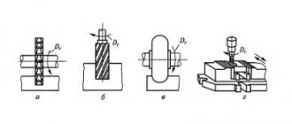
Solid countersinks with a conical shank (Fig. 82, a) are made short from 140 to 250 mm and long from 160 to 290 mm. These countersinks are designed to ream holes with a diameter of 10 to 32 mm. They have at least three teeth. The geometry of the tooth is characterized by angles α =8°, φ=60° and γ =20° (Fig. 82, b).
Rice. 82. Countersinks: a - solid with a conical shank, b - tail with a soldered hard alloy plate, c - mounted with a soldered hard alloy plate, d - mounted with insert knives, e - combined for countersinking and drilling
Tail countersinks with soldered hard alloy plates (see Fig. 82, b) are used for reaming holes with a diameter (from 14 to 38 mm. They are made short (from 160 to 290 mm) and long (from 190 to 350 mm).
Tail countersinks are made with three to four teeth. Tooth geometry: α=8°, φ=60°, γ=8°, γ1=0° - for countersinks equipped with VK hard alloy plates, and φ1=30° - for countersinks with TK alloy plates.
Mounted countersinks with soldered hard alloy plates (Fig. 82, c) are used to drill holes with a diameter of 34 to 80 mm. They are manufactured in lengths from 40 to 65 mm, with a number of teeth of at least four. The geometry of the teeth of these countersinks is the same as that of tail countersinks with soldered carbide plates. Attachment countersinks are connected to a mandrel mounted in the drilling machine spindle using a protrusion on the mandrel and a cutout at the end of the countersink.
Mounted countersinks with insert knives (Fig. 82, d) are used to drill holes with a diameter of 40 to 100 mm. They are manufactured in lengths from 45 to 70 mm, have the number of knives: four for countersinks with a diameter of 40 to 55 mm and six for countersinks with a diameter of 58 to 100 mm. Knives are made from high-speed steel P18 or P9.
When countersinking holes, combined tools are widely used, allowing you to combine countersinking with drilling or countersinking. In Fig. 82, d shows a combined countersink for drilling and countersinking holes directed along the conductor sleeve. The use of combined tools for simultaneous drilling and countersinking increases labor productivity.
Countersinking of holes is performed on drilling machines using electric and pneumatic machines in the same way as drilling.
Feed when countersinking is allowed 2-2.5 times more than when drilling. Allowances for processing holes by countersinking are taken according to table. 10. Table 10. Recommended allowances for processing holes by countersinking
| Hole diameter, mm | 10—18 | 18—30 | 30-50 | 50—80 | 80—100 |
| Diameter allowance, mm | 0,8—1 | 1—2 | 1,2—2,5 | 1,5—3 | 2—4 |