Mechanical properties characterize the resistance of a metal to deformation and destruction under the influence of mechanical forces (load).
The main mechanical properties include:
— strength — ductility — impact strength — hardness
Strength is the ability of a metal not to collapse under the influence of mechanical forces (load).
Plasticity is the ability of a metal to change shape (deform) under the influence of mechanical forces (load) without destruction.
Impact strength determines the ability of a metal to withstand impact (dynamic) mechanical forces (impact loads).
Hardness is the ability of a metal to resist the penetration of other harder materials into it.
Types and conditions of mechanical testing of metals
To determine mechanical properties, the following types of tests are performed:
— tensile tests; — static bending tests; — impact bending tests; — hardness measurement.
The conditions for testing samples include: temperature, type and nature of the application of load to the samples.
Test temperature:
— normal (+20°С); — low (below +20°С, temperature 0…-60°С); — high (above +20°С, temperature +100…+1200°С).
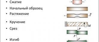
Type of loads:
| stretching |
| compression |
| bend |
| torsion |
| slice |
Character of load application:
— the load increases slowly and smoothly or remains constant — static tests; — the load is applied at high speeds; shock load - dynamic tests; — multiple repeated variable load; load changes in magnitude or in magnitude and direction (tension and compression) - endurance tests.
Mechanical test samples
Mechanical tests are performed on standard samples. The shape and dimensions of the samples are established depending on the type of test.
For mechanical tensile tests, standard cylindrical (circular cross-section) and flat (rectangular cross-section) samples are used. For cylindrical samples, samples with a diameter dо=10 mm, short lо=5×do = 50 mm and long lо=10×do = 100 mm are taken as the main ones.
Short round pattern
Long round pattern
Flat samples have a thickness equal to the thickness of the sheet, and the width is set to 10, 15, 20 or 30 mm.
Flat sample without heads for tensile grips
Flat sample with heads
Advantages and disadvantages of the method
First, about the unique capabilities of the technique:
- obtain data on the performance properties of welding;
- study the mechanical characteristics of connections;
- establish design values to determine maximum loads (data necessary for design work);
- the capabilities of the diffuse layer, the thermally affected zone, where internal defects are possible, are checked.
At low costs for studying samples, data are obtained by which the strength characteristics of serially produced parts are judged. Select the optimal welding option for various alloys.
The disadvantages are obvious. The samples are expected to be destroyed and cannot be restored. This control method cannot be used for acceptance of welded joints. Methods are needed for research at the stage of launching series into production.
A feature of mechanical testing of welded joints is the mandatory destruction of samples under multidirectional loads.
Mechanical properties determined by static tests
Static tests are those in which the applied load to the sample increases slowly and smoothly.
In static tensile tests, the following basic mechanical characteristics of the metal are determined:
— yield strength (σ t); — tensile strength or temporary resistance (σ in); — relative elongation (δ); — relative narrowing (ψ).
The yield strength is the stress at which a sample deforms without a noticeable increase in tensile load.
Ultimate strength is the stress at the maximum load preceding the failure of the sample.
Relative elongation is the ratio of the increment in the length of a sample after fracture to its initial length before testing.
Relative contraction is the ratio of the reduction in the cross-sectional area of a sample after fracture to its initial area before testing.
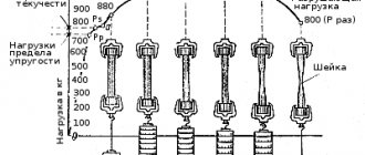
In static tensile testing, iron and other plastic metals have a yield plateau when the sample is elongated under a constant load Pm.
At maximum load Pmax, a narrowing of the cross section, the so-called “neck,” appears in one area of the sample. The destruction of the sample begins in the neck. Since the cross-section of the sample decreases, the destruction of the sample occurs at a load less than the maximum. During the test, the devices draw a tensile diagram from which the loads are determined. After testing, the destroyed samples are put together and the final length and diameter of the neck are measured. From these data, strength and ductility are calculated.
content .. 1 2 3 9 ..
2.4. Mechanical testing of metals
Mechanical testing of metals is the determination of the mechanical properties of metal alloys (metals for short), their ability to withstand various types of loads within certain limits. According to the nature of the effect on the metal, loads, and, accordingly, tests are divided into static (tension, compression, bending, torsion), dynamic (impact - impact strength, hardness), fatigue (repeated cyclic loading), long-term (exposure to atmospheric environments, creep, relaxation) and special. Of the variety of tests, the main ones are tensile, hardness, impact, bending and some others.
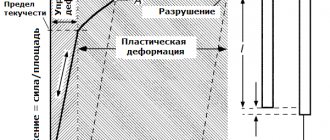
When testing metals for tensile strength, standardized samples and special machines are used. During testing, as the force increases, all changes occurring with the metal sample are recorded in the form of a diagram (Fig. 2.5) with coordinates: load along the ordinate axis and elongation along the abscissa axis. Using the diagram, the proportionality limit apt, the yield strength at, the maximum force - temporary resistance aD and rupture are determined. The proportionality limit is the highest stress (the ratio of force to the cross-sectional area of the sample), up to which direct proportionality between stress and strain is maintained when the sample is elastically deformed in proportion to the load, i.e. As the load increases, the elongation increases by the same amount. If the load is removed, the length of the sample will return to the initial one or increase slightly (by 0.03 ... 0.001%), determining the elastic limit.
The yield strength is the stress at which the sample deforms (elongates) without a noticeable increase in tensile load (horizontal area in the diagram). If the load is removed, the length of the sample will practically not decrease. With a further increase in the load on the sample, a stress is created that corresponds to the highest tensile load preceding the failure of the sample, called tensile strength ab (tensile strength). Further, the elongation of the sample increases, a neck is formed, along which the sample breaks.
The tension diagram makes it possible to judge the ability of a metal to deform (stretch) without breaking, i.e. characterizes its plastic properties, which can also be expressed by the relative elongation and narrowing of the sample at the moment of rupture (both parameters are expressed as a percentage).
Relative elongation is the ratio of the increase in the length of the sample at the moment before rupture to its original length. Relative contraction is the ratio of the reduction in the cross-sectional area of the specimen neck at the site of its rupture to the original cross-sectional area of the specimen.
Hardness testing is a simple and quick way to test the strength of a metal material (hereinafter referred to as metal for short) under complex stress conditions. In production, the most widely used methods are Brinell, Rockwell, Vickers, and some others. The surface layers of the tested metal should not have surface defects (cracks, scratches, etc.).
The essence of the method for determining hardness by the Brinell method (HB hardness) is to press a hardened steel ball into the test sample (product) under a given mode (load magnitude, loading duration). After the test is completed, the area of the imprint (hole) from the ball is determined and the ratio of the amount of force with which the ball was pressed to the area of the imprint in the test sample (product) is calculated.
Taking into account the expected hardness of the test sample from experience, balls of different diameters (2.5, 5 and 10 mm) and loads of 0.6...30 kN (62.5...3,000 kgf) are used. In practice, tables are used to convert the indentation diameter to the HB hardness number. This method of determining hardness has a number of disadvantages: the imprint of the ball damages the surface of the product; the hardness measurement time is relatively long; it is impossible to measure the hardness of products commensurate with the hardness of the ball (the ball is deformed); It is difficult to measure the hardness of thin and small products (they become deformed). In drawings and technical documentation, Brinell hardness is designated HB.
When determining hardness by the Rockwell method, a device is used in which an indenter - a hard tip 6 (Fig. 2.6) under the influence of a load penetrates the surface of the metal being tested, and not the diameter, but the depth of the indent is measured. The device is a desktop type, has an indicator 8 with three scales - A. B, C for reading hardness, respectively, in the ranges of 20 ... 50;
25… 100; 20 ... 70 scale units. The unit of hardness is taken to be the value corresponding to the axial movement of the indenter by 2 μm. When working with scales A and C, the tip is a diamond cone with an angle of 120° at the apex or a carbide cone. The diamond cone is used when testing hard alloys, and the carbide cone is used for non-critical parts with a hardness of 20...50 units.
Rice. 2.6. Rockwell device for determining hardness: I - load release handle; 2 - load; 3 - flywheel; 4 — lifting screw; 5 - table; 6 — tip of the device; 7 - sample of the tested metal; 8 - indicator
When working with scale B, the indenter is a small steel ball with a diameter of 1.588 mm (1/16 inch). Scale B is intended for measuring the hardness of relatively soft metals, since with significant hardness the ball is deformed and penetrates into the material weakly, to a depth of less than 0.06 mm. When using a C scale, the tip is a diamond cone; in this case, the device measures the hardness of hardened parts. In production conditions, as a rule, the C scale is used. The tips are pressed in at a certain load. So, when measured on scales A, B and C, the load is 600, respectively; 1 LLC; 1,500 N, hardness is designated in accordance with the scale - HRA, HRB, HRC (its values are dimensionless).
When working on a Rockwell instrument, a sample of the test metal 7 is placed on the table 5 and, using the flywheel 3, the lifting screw 4 and the load 2 create the required force on the tip 6, recording its movement on the indicator scale 8. Then, by turning the handle 7, the force is removed from the test metal and determined hardness value on the hardness tester scale (indicator).
The Vickers method is a method for determining the hardness of a material by pressing a diamond tip (indenter) into the test product, having the shape of a regular tetrahedral pyramid with a dihedral angle at the apex of 136°. Vickers hardness HV is the ratio of the load on the indenter to the area of the pyramidal surface of the indentation. Selection of pressing load
50... 1000 N (5... 100 kgf) depends on the hardness and thickness of the sample being tested.
Other methods of testing metals for hardness are known, for example, using the Shore device and dynamic indentation of a ball. In cases where the hardness of a hardened or hardened and ground part needs to be determined without leaving any trace of the measurement, the Shore device is used, the principle of operation of which is based on elastic recoil - the height of the rebound of a light striker (striker) falling on the surface of the test body with a certain height.
Hardness on the Shore device is assessed in conventional units proportional to the rebound height of the diamond-tipped striker. The estimate is approximate, since, for example, the degree of elasticity of a thin plate and a massive part of large thickness with the same hardness will be different. But, since Shore’s device is portable, it is convenient to use for testing the hardness of large parts.
To roughly determine the hardness of very large products (for example, a rolling mill shaft), you can use a manual Poldi device (Fig. 2.7), the action of which is based on dynamic indentation of the ball. In a special holder 3 there is a firing pin 2 with a collar against which a spring 7 rests. A steel ball 6 and a reference plate 4 with a known hardness are inserted into the slot located in the lower part of the holder 3. When determining hardness, the device is installed on the part being tested 5 at the measurement location and the upper part of the striker 2 is struck with a hammer 1 with medium force once. After this, the sizes of the imprints of the holes on the part being tested 5 and the reference plate 4, obtained simultaneously from the ball when hitting the striker, are compared. Next, the hardness number of the test product is determined using a special table.
In addition to the considered hardness testers, universal portable electronic hardness testers TEMP-2, TEMP-Z are used in production, designed to measure the hardness of various materials (steel, copper, aluminum, rubber, etc.) and products made from them (pipelines, rails, gears, castings , forgings, etc.) using the Brinell (HB), Rockwell (HRC), Shore (HSD) and Vickers (HV) scales.
Rice. 2.7. Manual Poldi device for determining hardness: 1 - hammer; 2— striker; 3 — clip; 4—reference plate; 5 - part being checked; 6 — ball; 7 - spring; — — direction of force to the firing pin
The principle of operation of hardness testers is dynamic, based on determining the ratio of the impact speed and rebound of the striker 6 (Fig. 2.8) (ball 7 with a diameter of 3 mm), which is converted by the electronic unit 1 into a three-digit number of conditional hardness, displayed on the liquid crystal (LC) indicator 2 (for example, 462). Based on the measured number of conditional hardness, using conversion tables, the hardness numbers corresponding to the known hardness scales are found.
Rice. 2.8. Portable electronic hardness tester TEMP-Z: 1 - electronic unit; 2 - LCD indicator; 3 - pusher; 4 — release button; 5 - sensor; 6 - drummer; 7 - ball; 8 — support ring; 9 - tested surface of the product
To measure hardness by this method, the device is prepared as follows. Using a pusher 3 located on the electronic unit 1, the ball 7 located in the sensor 5 is pushed into the collet clamp and at the same time the release button 4 located on top of the sensor 5 is cocked. Next, the sensor is tightly pressed with the support ring 8 to the test surface 9 of the product and the release button is pressed. 4. After the impact of the striker 6 with the test surface of the product, the result will appear on the LCD indicator in the form of a three-digit number of conditional hardness.
The final value of the measured conditional hardness is the arithmetic mean of five measurements. Once a year, periodic verification of the device is carried out, using standard hardness measures not lower than the second category of the corresponding hardness scales (Brinell, Rockwell, Shore and Vickers), while observing standardized conditions. Using these instruments, in addition to hardness, it is possible to determine tensile strength (tensile strength) and yield strength.
Along with hardness testers, calibrated files are used in production to determine the hardness of a material. With their help, the hardness of steel parts is controlled in cases where there is no hardness tester or when the area for measurement is very small or the place is inaccessible to the indenter of the device, as well as when the product has very significant dimensions. Tared files are files with a known hardness, made of U10 steel; they are triangular, square and round with a certain notch. The adhesion of the file notch to the controlled metal is determined by the presence of scratch marks on the controlled part without crushing the tops of the teeth on the file. During operation, the sharpness of the file teeth should be periodically checked for adhesion to control samples (rings). Files are manufactured in two hardness groups, respectively, to control the lower and upper limits of the hardness of products. Control rings (plates) make types with a hardness of 57...59; 59…61 and 61…63 HRC for checking calibrated files, the hardness of which corresponds to the hardness limits of control samples.
Impact test (impact bending)
is one of the most important characteristics of the (dynamic) strength of metals. It is also especially important to test products operating under shock and alternating loads and at low temperatures. In this case, a metal that easily breaks under impact without noticeable plastic deformation is called brittle, and a metal that breaks under impact after significant plastic deformation is called ductile. It has been established that a metal that works well when tested under static conditions is destroyed under impact loading, since it does not have impact toughness.
To test impact strength (resistance of a material to impact loads), a Charpy pendulum pile driver is used (Fig. 2.9), on which a special sample is destroyed - a mena, which is a rectangular steel bar with a one-sided U- or V-shaped cut in the middle. The pendulum of the pile driver strikes the sample from a certain height on the side opposite to the cut, destroying it. In this case, the work done by the pendulum before and after the impact is determined, taking into account its mass and the heights of the fall H and rise h after the destruction of the sample. The difference in work is attributed to the cross-sectional area of the sample. The quotient obtained by division characterizes the impact strength of the metal: the lower the viscosity, the more brittle the material.
Bending tests are carried out on brittle materials (hardened steel, cast iron), which fail without noticeable plastic deformation. Since it is not possible to determine the moment of the beginning of destruction, bending is judged by the ratio of the bending moment to the corresponding deflection. In addition, a torsion test is carried out to determine the limits of proportionality, elasticity, fluidity and other characteristics of the material from which critical parts (crankshafts, connecting rods) operating under high torsional loads are made.
Rice. 2.9. Charpy pendulum pile driver: 1 - pendulum; 2 - sample; H, h - heights of fall and rise of the pendulum; - - trajectory of movement of the pendulum
In addition to those discussed, other tests of metals are carried out, for example, for fatigue, creep and long-term strength. Fatigue is a change in the state of the material of a product before its destruction under the influence of repeated alternating (cyclic) loads that change in magnitude or direction, or both in magnitude and direction. As a result of long service, the metal gradually passes from a plastic state to a brittle state (“tires”). Fatigue resistance is characterized by an endurance limit (fatigue limit) - the highest cycle stress that a material can withstand without destruction, for a given number of repeated-variable loadings (loading cycles). For example, 5 million loading cycles are established for steel, and 20 million for light cast alloys. Such tests are carried out on special machines in which the sample is subjected to alternating compressive and tensile stresses, alternating bending, torsion, repeated impact loads and other types of force.
Creep (creep) is a slow increase in plastic deformation of a material under the influence of a long-term load at a certain temperature, less than the load that creates residual deformation (i.e. less than the yield strength of the part material at a given temperature). In this case, plastic deformation can reach such a value that changes the shape and dimensions of the product and leads to its destruction. Almost all structural materials are subject to creep, but for cast iron and steel it is significant when heated above 300 °C and increases with increasing temperature. In metals with a low melting point (lead, aluminum) and polymeric materials (rubber, caoutchouc, plastics), creep occurs at room temperature. The metal is tested for creep in a special installation in which the sample at a given temperature is loaded with a load of constant mass for a long time (for example, 10 thousand hours). At the same time, the amount of deformation is periodically measured with precise instruments. With increasing load and increasing temperature of the sample, the degree of its deformation increases. The creep limit is a stress that in 100 thousand hours causes an elongation of the sample at a certain temperature of no more than 1%. Long-term strength is the strength of a material that has been in a state of creep for a long time. Long-term strength limit is the stress that leads to the destruction of a sample at a given temperature for a certain time corresponding to the operating conditions of the products.
Testing of materials is necessary to create reliable machines that can operate for a long time without breakdowns or accidents in extremely difficult conditions. These are airplane and helicopter propellers, turbine rotors, rocket parts, steam pipelines, steam boilers and other equipment.
For devices operating in other conditions, specific tests are carried out to confirm their high reliability and performance.
Mechanical impact testing
Dynamic tests are those in which the rate of deformation is significantly higher than in static tests.
Dynamic impact bending tests reveal the tendency of a metal to undergo brittle fracture. The method is based on the destruction of a sample with a notch (stress concentrator) with one blow of a pendulum pile driver.
The standard provides for samples with three types of notches:
U-shaped sample with radius R = 1 mm (KCU method);
V-shaped sample with radius R = 0.25 mm (KCV method);
sample I – shaped with a fatigue crack (KST method).
Impact strength is understood as the work of impact related to the initial cross-sectional area of the sample at the concentrator location.
After the test, the impact work required to destroy the sample is determined using the pendulum pile driver scale. The cross-sectional area of the sample is determined before failure.
DETERMINATION OF HARDNESS OF METALS
Hardness is the property of a metal to resist plastic deformation in the surface layer when a ball, cone or pyramid is indented. Hardness measurement is simple and quick to carry out and is performed without destroying the product. Three methods for determining hardness are widely used:
— Brinell hardness (hardness unit is designated HB); — Rockwell hardness (hardness unit is denoted by HR); — Vickers hardness (hardness unit is designated HV).
Determination of Brinell hardness consists of pressing a steel ball with a diameter of D = 10 mm into the sample (product) under the influence of a load and measuring the indent diameter d after removing the load.
Brinell hardness is designated by numbers and letters HB, for example, 180 HB. The smaller the diameter of the print, the higher the hardness. The higher the hardness, the greater the strength of the metal and the less ductility. The softer the metal, the less the load on the device is set. So, when determining the hardness of steel and cast iron, the load is taken to be 3000 N, for nickel, copper and aluminum - 1000 N, for lead and tin - 250 N.
Determination of Rockwell hardness consists of pressing a tip with a diamond cone (scales A and C) or a steel ball with a diameter of 1.6 mm (scale B) into the test sample (product) under the action of sequentially applied preliminary (Po) and main (P) loads and in measurement tip penetration depth (h). Rockwell hardness is indicated by the numbers and letters HR indicating the scale. For example, 60 HRC (hardness 60 on the C scale).
Determination of Vickers hardness consists of pressing a diamond tip shaped like a regular tetrahedral pyramid into the sample (product) under the influence of a load and measuring the diagonal of the indentation d remaining after removing the load. The method is used to determine the hardness of thin parts and thin surface layers with high hardness. Vickers hardness is designated by numbers and letters HV, for example, 200 HV.
Static bending tests
Technological tests for static bending are used to determine the ability of a metal to accept a bend given in shape and size. Similar tests are carried out on welded joints.
Bend tests are carried out on samples made of sheet and shaped (rod, square, angle, channel, etc.) metal. For sheet metal, the sample width (b) is taken to be equal to double the thickness (2•t), but not less than 10 mm. The radius of the mandrel is indicated in the technical specifications.
There are three types of bending:
- bend to a certain angle; - bend around the mandrel until the sides are parallel; - bend close until the sides touch (flattening).
The absence of cracks, tears, delaminations or fractures in the sample is a sign that the sample has passed the test.
Features of mechanical research
The main feature is that mechanical studies are destructive control methods. Those. in most cases, the samples under study are destroyed or damaged. But if destruction is not the best option in a particular case, other testing methods must be chosen.
The room where experiments are carried out must be maintained at the same temperature. The data obtained during the inspection must be recorded.
To obtain the most accurate results, several samples from the same batch are tested. It is likely that results will vary. Then the average value is derived from the obtained indicators - this will be the most accurate result.
It is advisable to use mechanical tests in the serial production of parts, when from each circulation they take the number of products regulated by standards and conduct research. It will not be possible to issue a correct conclusion using only one sample. If the product is single, it is worth using non-destructive testing methods.
Test results depend on various factors. This includes both the original state of the workpiece and the presence of defects in the metal. Therefore, before determining technical characteristics, it is necessary to carry out flaw detection of welded joints, for example, ultrasonic testing.