Purpose and scope of application
Turning cutters belong to the main type of tools in metal and woodworking installations operating at high speed, including CNC, GPS, GPM (even on manually operated lathes).
The blanks acquire the required shape and size in contact with the part. They are classified according to the type of processing, method of attachment, direction of feeding movement, purpose.
Compared to solid versions, a replaceable insert located on the cutting edge must be replaced in case of wear or the need for another type of work. This allows you to significantly speed up the production process and expand the range of interaction with work surfaces.
The following operations are carried out using carbide elements:
- surface treatment of the workpiece;
- thread cutting;
- boring the inner surface;
- scan;
- cutting glass, getinaks, non-ferrous metal;
- selection of grooves, recesses, grooves.
To get a consultation
regarding tools, processing methods, modes, or select the necessary equipment, you can contact our managers or CAD department
You can also select and purchase cutting tools and equipment for the machine, made in Taiwan, Israel
By submitting an application, you agree to the privacy policy
Turning cutters are the main working tool of wood and metalworking machines, through which the processed workpieces are given the required shape and size. The classification of turning cutters is carried out according to factors such as purpose, type of processing, method of feeding and fastening, which we will discuss in more detail in this article.
The publication discusses the types of turning cutters and their design, provides recommendations for choosing a tool and the technology for its installation, and also provides instructions by following which you can properly sharpen the cutter with your own hands.
Design
A turning cutter consists of two structural parts: a holder, with the help of which the tool fits into the mounting groove of the machine, and a cutting head. The holder is made in a rectangular or square shape and is the main part of the device.
The head consists of an edge sharpened at the required angle and several planes; it is the working part of the device; during processing it gives the workpiece the required shape. The sharpening angle affects how the cutter removes metal from the workpiece.
By design, cutters are divided into several types:
- straight: the holder and the working head are located on one axis, or on two parallel ones;
- curved: when viewed from the side, a curved holder is visible;
- bent: viewing the tool from above, the bend of the working part is clearly visible;
- drawn: the width of the holder is greater than the working head, drawn to the left or right. The axes of both parts of the part coincide or are displaced. A
Current standards
The requirements for each type of product are indicated in the State Standard:
- GOST 19086–80 - characterizes chipbreakers, supporting, cutting elements;
- GOST 19042–80 - classifies the shape of the system for defining replaceable plates;
- GOST 25395–90 - designated for the production of inserts made of several types of hard alloys, mounted on a cutter holder using a brazed type (through-type, turret, boring type cutters).
Main Dimensions
GOST provides the following dimensions for holders.
- Rectangular shape (mm): 16x10; 20x12; 25x16; 25x20; 50x25; 40x32; 50x32; 50x40; 63x50.
- Square shape (mm): 4x4; 6x6; 8x8; 10x10; 12x12; 16x16; 20x20; 25x25; 32x32; 40x40.
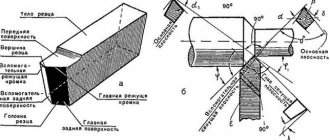
Lathe cutter design
The basis of the cutter is a rod fixed in the cutter holder. A cutting element, the head, is installed in the front part of the rod. The cutter has several surfaces. Chips run off the front surface. The rear surfaces, main and auxiliary, face the part. The main cutting edge, lying at the intersection of the front and main back surfaces, cuts the metal.
Classification of incisors
Turning cutters differ:
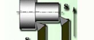
- In the direction of delivery. The right cutters move during the working feed from the tailstock to the front (from right to left). The left is making the opposite labor movement.
- According to the type of working head: straight, bent incisors.
- Turning cutters are produced as one-piece and composite ones. The compound cutter is made with an attached head made of expensive steel.
- According to the geometric section of the rod.
The cutting part of turning tools can be made of carbon and carbide steels (“Pobedit”), diamond and mineral-ceramic materials.
Determining the working direction of the cutter is simple. When installing, the cutting edge should be directed towards the workpiece.
Types of turning tools
Walkthroughs. Used for processing external cylindrical surfaces. Performed for working passage in both directions. A bent cutter can process ends during transverse feed.
Passing persistent. They are used to process stepped parts and trim the ends. Such cutters ensure perpendicularity of adjacent planes of steps. Can be either right or left. They are made of hard alloys by soldering onto a rod.
Trimming. They machine the stepped profile of a part, trim the ends and beads, and are capable of processing external cylindrical surfaces. The carbide cutting part is made by soldering onto the base.
Boring. The diameter of the holes prepared by drilling is increased (bored). Boring is carried out in several stages with the formation of a stepped surface at the end. Then, using a cross feed, the steps are cut until perpendicular surfaces are formed.
Cut-off. The finished part is separated from the workpiece, grooves and grooves are machined. Processing is carried out at right angles to the part with a working part made of high-speed and hard alloys.
Cutting internal and external threads is carried out using thread cutters . Shaped sharpen surfaces of complex shapes and grooves.
Automatic turret cutters
They are used on automatic turret lathes in mass production.
Longitudinal turning cutters. Automatic cutters made of high-speed steel are made by soldering or mechanically attaching the cutting part to a rod. The tool, depending on the installation in relation to the part, can be radial or tangential, which is ensured by special sharpening, as well as the design of the holder installed in the turret. By rotating the holder, the cutters are installed at different angles in relation to the workpiece.
Read also: How to measure the cross-section of a wire with a caliper
Grooving and parting cutters. Installed on transverse supports of automatic machines. They have a design similar to cutters for conventional lathes. Since automatic machines mainly work with bar blanks, the cutting cutter, having a specific sharpening, not only cuts off the finished part, but also processes the end of the next part.
Advantages and disadvantages
Cutters with replaceable inserts have the following advantages:
- quick replacement of the main part of the part;
- Compliance with most machines and devices;
- the ability to quickly change cutting elements;
- wear resistance, high degree of reliability at high speeds;
- low price of components;
- commonality of cutting elements;
- increasing the service life of the cutter holder due to the use of removable elements made of hard alloys.
Among the shortcomings noted:
- high cost of imported parts compared to domestic ones;
- Incorrect fastening of the plate leads to damage to the tool and reduces its service life.
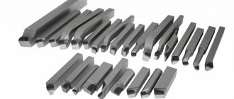
Types and purpose of cutting tools
According to their design, cutting tools are divided into all-metal and prefabricated. The first ones are made of tool steel, and their standard sizes and designation rules are regulated by GOST 18874-73. The maximum GOST dimensions of such a cutter are: total length - 80 mm, head length - 15 mm, blade width - 12 mm. With this tool, as the cutting edge is sharpened, the length of the head decreases and, consequently, the maximum cutting diameter decreases.
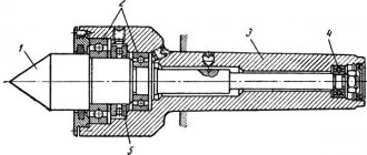
Prefabricated cutting tools can be divided into two main types. The first includes a cutting tool in which the holder and head are made of one piece of metal, and the cutting plate is a separate assembly element mounted at the end of the head. There are two main types of fastening, according to which cutters with mechanical and soldered fastening of plates are distinguished. The second type is a prefabricated cutting tool that has recently become widespread, in which a flat and long head with a cutting part is mechanically attached to a special mandrel that acts as a holder (see figure below). These cutters come with replaceable inserts of varying widths and thicknesses. In addition, some of them have adjustable head extension length.
In addition to normal and reinforced cutting tools of traditional design, there are a number of varieties for working in special conditions, including those that compensate for the shortcomings of low-power and non-rigid turning equipment. These include spring and inverted cutters, which are mainly used in home workshops and small industries. Spring cutters have an arched head and are designed for processing materials with an uneven and hard surface on small machines with a flexible structure. This head compensates for dynamic shocks and smoothes out vibration, which allows you to achieve the desired surface quality and protect the cutting insert from damage.
Inverted cutters became popular five or six years ago when a very easy to use and efficient cutting insert was developed.
Features and advantages of inverted cutting tools
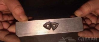
This type of cutting tool got its name due to the fact that it operates on a reverse (counterclockwise) spindle rotation. The design itself resembles a stationery knife: a holder and a long blade in the form of a plate with a bevel at the end. The blade is made of high-speed steel alloyed with cobalt and in cross-section looks like an inverted letter “T” with short crossbars (see picture below). The sharpening angle of the end of the cutting edge is 7º, the size range of thicknesses produced by the manufacturer is from 1 to 3.2 mm.
The main advantage of this cutter is the facilitated removal of chips, since when the spindle rotates in reverse, it immediately goes down under its own weight. With this mode, the likelihood of clogging the groove with chips is sharply reduced, which is often the cause of jamming and tool breakage. Other advantages of this model include:
- ease of sharpening the blade;
- work at long reach;
- improved cooling mode (chips from below, coolant from above);
- long service life even with repeated sharpening of the plate.
In addition, its arbor has a precise height adjustment system, which eliminates the need to adjust the position of the tool using shims.
Toolholder classification
Turning holders are divided into several types, depending on the type of fixation.
ISO C mounting system
Classic connection system “Clamp from above” for plates without holes. Used for external and internal roughing, end trimming, turning along the workpiece. When using, the structure of the chipbreaker is taken into account. Provides rigid fixation of the part and good cycle repeatability.
ISO D system for metal cutting machine
Double clamping of the bracket guarantees strong fixation of the plate and reliable positioning in the cutter. Used for inserts with a hole for cutting large amounts of chips.
Recommended for roughing, finishing, and finishing operations on large diameter holes. Ensures unhindered chip flow and quick insert replacement. Suitable for fastening ceramic and carbide parts.
ISO M fastening system cutter
Indicates pressing from above and pressing behind the hole. Allows single-sided plates to be secured without back corners. Provides reliable, rigid clamping with simultaneous pressure on the plate and the inside of the socket.
ISO S system
Screw fastening is used primarily for fixing small-sized tools when boring small-diameter holes. And also for external processing of parts of reduced rigidity.
The most compact, reliable fastening system, ensuring free flow of chips, does not require a large number of components (compared to the old type of fixation with a top clamp).
Mechanical mount selection
When choosing a turning tool, the following factors are taken into account in order to optimize production.
- The shape, dimensions of the part, as well as the cleanliness of processing, its accuracy, indicating the direction of movement of the tool, the sequence of the process.
- The type of operation that influences the choice of cutting part: part cutting, threading, turning, grooving, etc.
- The structure of the cutting plate, the amount of input, and the speed of rotation of the part affect the accuracy and degree of surface roughness of the part.
- For external processing and boring of products, different cutters and carbide inserts are chosen.
- Rigidity of the workpiece, tool, processing conditions of the part. For example, in vibration conditions, pay attention to the size of the device, and take into account the geometry of the tool.
- The method of fixation, the dimensions of the tool fit, depending on the design, dimensions of the machine, as well as its power and technological capabilities.
- Workpiece material: cast iron, stainless, alloy or carbon steel.
- Productivity, tool efficiency, influencing the quality of processing. Batch size, equipment downtime, etc.
- Preservation of the range of tools used in production, which affects the level of optimization.
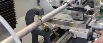
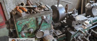
Turning
Lathe cutter device
|
Materials for turning tools. The main requirement for the material of the working part of the cutter is hardness, which must be greater than the hardness of any material processed by this cutter. Hardness should not noticeably decrease due to cutting heat. At the same time, the cutter material must be sufficiently viscous (not brittle); The cutting edge of the cutter should not chip away during operation. The cutter material must have good resistance to abrasion, which occurs from the friction of the chips on the front surface of the cutter, as well as from the friction of the back surface of the cutter on the cutting surface.
These requirements are met to varying degrees by tool materials - metal-ceramic hard alloys, mineral ceramics, high-speed and carbon steels of various grades. The most modern materials for turning cutters are metal-ceramic hard alloys, which retain their cutting properties when heated during operation to a temperature of 800-900 ° C. These alloys consist of the finest grains of carbides of refractory metals - tungsten, titanium and tantalum, cemented with cobalt. Meta and locker-amic hard alloys are divided into three groups: tungsten, titanium-tungsten and titanium-tantalum-tungsten.
Tungsten carbide alloys are intended for processing cast iron, non-ferrous metals and their alloys and non-metallic materials. For the manufacture of turning cutters, tungsten hard alloys of the brands VK2, VKZM, VK4, V KG, VK6M, VK8, VK8V are used. The letter B in each of these brands means tungsten carbide, the letter K means cobalt; the number in the stamp after the letter K indicates the amount (in percentage) of cobalt contained in this alloy. The rest is tungsten carbide. Thus, for example, a VK2 alloy contains 2% cobalt and 98% tungsten carbide. The letter M, shown at the end of some brands, means that this alloy is fine-grained (grain size 0.5-1.5 microns). The letter B is assigned to the grade of the alloy if it is coarse-grained (grain size 3-5 microns).
Lathe cutter design
|
The fine-grained nature of the alloy gives it wear resistance greater than the wear resistance of a normal alloy of the same grade, with less strength and resistance to shock, vibration and chipping. The coarse grain of the alloy, on the contrary, increases its strength and resistance to shock, vibration and chipping and reduces the wear resistance of the alloy. Titanium-tungsten hard alloys are used for processing all types of steels. When turning, alloys of grades T5K10, T5K12V, T14K8, T15K6, T30K4 are used. In each of these brands, the letter T and the number following it indicate the amount (in percent) of titanium carbide contained in this alloy, and the number after the letter K indicates the content (in percent) of cobalt. The rest of this alloy is tungsten carbide. Thus, for example, an alloy of the T5KYu brand contains 5% titanium carbide, 10% cobalt and 85% tungsten carbide. Titanium-tantalum tungsten alloys are used in particularly difficult cases of steel processing. Currently, only one grade of this alloy has been introduced into GOST, namely TT7K12, the content of which is 7% titanium and tantalum carbides, 12% cobalt and 81% tungsten carbide.
Metal-ceramic alloys are produced in the form of plates of various shapes and sizes. Recently, under certain conditions, mineral-ceramic materials, the main part of which is aluminum oxide, are used as tool materials. These materials do not contain relatively rare elements: tungsten, titanium, cobalt, etc. The heat resistance of cutters equipped with mineral ceramics is very high and reaches 1200 ° C or more. This is the main advantage of mineral-ceramic materials in comparison with hard alloys, the main components of which are rare and expensive elements and whose heat resistance is lower. The disadvantage of the mineral-ceramic alloy is its relatively low and unstable bending strength (brittleness). Therefore, it is used for semi-finishing and finishing machining of cast iron, steel and non-ferrous alloys. Mineral ceramic materials are also produced in the form of plates.
Turning tool angles
|
For the manufacture of turning tools, high-speed steel grades P18 and P9 are used. The main elements of high-speed steel grade P18, most widely used for the manufacture of cutters, are tungsten (17.5-19%) and chromium (3.8-4.4%), giving the steel the property of self-hardening and heat resistance when heated to approximately 600 ° C Carbon (0.70-0.80%), which is part of the steel in question, combines with tungsten and chromium, increasing its hardness. In addition, P18 high-speed steel contains a small amount (1.0-1.4%) of vanadium. The less common high-speed steel grade P9 contains tungsten {8.5-10.0%), chromium (3.8-4.4%), carbon (0.85-0.95%), vanadium (2.0- 2.6%) and other elements that do not have a significant impact. In addition to steels R18 and R9, in recent years high-speed steels of the grades R18F2, R14F4, R9F5, R18K5F2, R10K5F5 and R9K9 have been used for the manufacture of turning tools. The letter P in these stamps stands for tungsten, the letter F for vanadium, and the letter K for cobalt. The numbers after the letters determine the percentage content of these elements in a given steel. In addition to the elements that characterize these steel grades and are indicated in their designations, these steels also contain carbon, chromium, molybdenum and other components.
You can determine the material of a cutter if there is no marking on it “by a spark.”
When sharpening a high-speed steel cutter, a small amount of red sparks, similar to stars, are formed. The more tungsten in the steel, the darker the sparks and the fewer of them. Of carbon steels, steel grades U12A and U10A are used for the manufacture of cutters. In these brands, the letter U conventionally means that the steel is carbon; the numbers following it indicate the average carbon content in tenths of a percent, and the letter A also conventionally indicates that the steel is high quality. Thus, the U12A grade denotes high-quality carbon steel with an average carbon content of 1.2%. In addition to carbon, these steels contain manganese, silicon, chromium, nickel, sulfur and phosphorus. When sharpening a carbon steel cutter, many yellow sparks are produced in straight lines. When heated to 200° C, carbon steel cutters lose their durability and become unsuitable for further work. Therefore, at present they are used very rarely and mainly for processing soft and medium-hard materials at low cutting speeds.
Metal cutting modes
The cutting mode is a set of values calculated by calculation.
- Depth , which determines the thickness of the layer to be removed in one operation. When processing the end, the depth indicator is determined by the diameter of the part; for flat parts, the length is used.
- Speed . It is calculated by multiplying the number of revolutions per minute of the part by its diameter. This takes into account the type of operation being performed, the type of tool, and the material of the workpiece.
- Submission . An indicator of the movement of the cutter per revolution of the part. After calculation, these values are compared with the standard indicators specified in the machine passport.
Also, when calculating the cutting mode, the parameters of turning equipment are taken into account:
- power, spindle speed and others.
Equipment prices
Most often, sets consisting of cutters with plates are presented for sale. As practice shows, the use of replaceable elements significantly saves the cost of purchasing components. The cost is affected by the modification, configuration, and brand of products.
- a set of cutters and plates made in Germany costs 5,300-7,200 rubles, depending on the size;
- China offers from 283 to 710 rubles per set;
- Stalex and Jet (Switzerland) have almost the same price - about 6,400 rubles.
When choosing cutters with replaceable inserts, study the markings of the holders and pay attention to the quality and structure of the head and holder. An incorrectly selected tool will complicate the processing of parts and will negatively affect the outcome of the work performed.