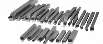
Versatile through-cut turning tools
Universal pass-through turning tools come in left- and right-handed varieties; left-handed ones carry out processing from left to right, and right-handed ones, on the contrary, from right to left. The most common are the right incisors.
Left and right passing incisors
Also, through cutters are divided into the following types:
1. Passing straight cutters , these cutters are not widely used and are mainly used for processing external cylindrical surfaces.
Passing straight cutter
2. Passing bent incisors , in such incisors the working part is bent to the right or left. These cutters are used for processing the end of the workpiece and for chamfering.
Passing bent cutter
3. Passing persistent bent cutter , usually called simply passing persistent . This type of turning cutter is the most common in work, as it allows you to remove the largest allowance in one pass. Conducts processing along the axis of rotation.
Passing persistent bent cutter
4. Scoring bent cutter , the main difference between this cutter and the continuous persistent bent cutter is that the melon cutter processes perpendicular to the axis of rotation, as well as the shape of the cutting plate. In a bent through cutter it is triangular.
Scoring bent cutter.
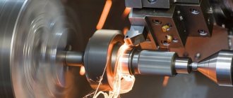
Cutting modes
Cutting modes are a set of parameters that determine the conditions for processing parts using a turning tool. The cutting process is influenced by the following factors:
- Cutting speed is the path of movement of the machined surface of the workpiece relative to the cutting edge per unit time. Measured in m/min or m/s. In the drawings it is designated by the Latin letter V.
- Feed is the path traveled by the cutting edge in 1 stroke or revolution of the workpiece being processed. Measured in mm/rev. In the drawings it is marked with the Latin symbol S.
- Depth of cut is the distance between the machined and machined surfaces. It shows the amount of metal layer being removed. In the diagrams it is denoted by the Latin letter t.
- The cross-sectional area of the cut layer is the product of the cutting depth and the feed. It is a nominal value and affects the presence of roughness. In the diagrams it is indicated by the Latin symbol f.
These parameters are tabular values and are specified in GOST 25762-83.
Download GOST 25762-83
Each type of cutting tools with mechanically fastened inserts has additional cutting modes. Cutting cutters carry out transverse movements, boring tools move longitudinally relative to the surface of the workpiece. During operation, the average speed of the cutting edges is tenths of mm. The feed is 0.1 mm/rev.
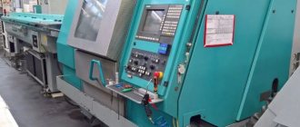
Modern continuous turning tools
Modern straight turning tools also come in a variety of shapes and sizes and basically consist of a holder and a replaceable carbide insert that is screwed to the holder.
Design of a modern through cutter
Since these cutters are mainly installed on CNC machines, they can process quite different geometries and there is no need to use two different cutters to process a cylindrical surface and trim the end.
Typically, when processing, two cutters with a replaceable insert are used. One rough and the other finishing.
A cutter with a replaceable insert for roughing in the picture below.
Cutter with replaceable insert for roughing
And a finishing cutter.
Cutter with indexable insert for finishing
As you can see, the finishing cutter is sharper, which allows for better surface roughness.
But let’s not delve into the technology of processing parts; let’s better figure out how to get 3D models of cutters in SolidWorks .
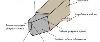
Cutter geometry
The main working surface of the cutter will be its head, which is located on the very rod of the device. It is inserted into the tool holder for subsequent work. The front surface of the head will have a predominant surface that will ensure high-quality chip flow. There are also two trailing edges - the main and auxiliary. They should be called those surfaces that will face the part undergoing the processing process.
The main work will be done using the main cutting edge . It is created at the intersection of the main back and front surfaces in the tool. In the design of the device itself there is also an auxiliary cutting edge, which is formed at the intersection of the main, rear and front structures. The intersection of the secondary type and the main cutting edge will create a special point in the cutter. Each model will have its own angle created, which will make the product most suitable for certain application purposes. For example, for the process of machining a step-type part, it is worth using a cutter with a total angle of about 90 degrees.
Where to get a 3D model of cutters for SolidWorks
The 3D models of the cutters presented above can, of course, be built in SolidWorks using the lessons from this page. Dimensions can be taken from the websites of cutter manufacturers or catalogs.
Or an easier way - you can simply download these models!
All the most popular manufacturers post publicly available 3D models of the tool on their websites, mainly in .stp format.
Let's take, for example, a tool manufacturer like Sandvik coromant. The website of this manufacturer can be easily found in a search engine.
We go to it and enter the designation of the holder “ SCLCR 2525M 12” (It is used for rough turning).
We open the page for this tool and see in the download section that this holder is available for download.
Link to download the 3D model of the tool on the Sandvik coromant website
Download it and open it in SolidWorks.
Through cutter for CNC machines in SolidWorks.
I recommend resaving the downloaded files in the SolidWorks format for further work.
Next, in the same way, download the cutters under the designations: SVJBL 2525M 16 , SVJBR 2525M 16 (they are mainly used for finishing). And we also open them in SolidWorks and resave.
Cutters SVJBL 2525M 16, SVJBR 2525M 16 in SolidWorks
As you can see, getting a detailed 3D model of a cutter for Solidworks is quite simple and quick.
At the end of the article, let’s watch a video animation of the processing of incisor data.
Marking according to GOST
Requirements for the production of metalworking machines, as well as auxiliary equipment, are strictly regulated by the requirements of interstate standards.
There are much fewer requirements for the rods of cutting devices compared to the elements of the contact group. They are made from steel grade 45 or 50.
There is a separate standard for each type of design. For example, the production of cutters with upper clamping of a replaceable plate is regulated by GOST 26611-85.
In the production of high-speed steel plates, cobalt compounds are used:
After heat treatment, their hardness reaches 67 HRC.
There are special requirements for the surface roughness of devices. After finishing the front and rear parts, the degree of cleanliness must correspond to class 9.
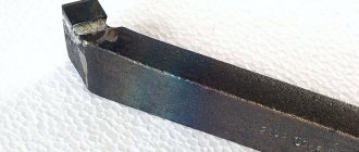
Symbols in accordance with the requirements of the interstate standard are applied to the side surface.
As an example, let's decipher the T15K6 marking:
- "T". The first letter indicates that a solid composition of the titanium group was used as the manufacturing material.
- "15". The number indicates the mass fraction of titanium carbide in the product.
- "TO". The product contains cobalt.
- "6". Mass fraction of the above chemical element.
Design features
Each metal turning tool consists of the following main parts:
- holder. Designed for fixation on a turning device;
- working head. Used for processing parts.
The working head of a metal-cutting device contains various planes and edges. Their sharpening angle depends on the characteristics of the steel from which the part is made and the type of processing. The cutter holder for a metal lathe usually has a square or rectangular cross-section.
Structurally, it is possible to distinguish the following types of cutters:
- Direct. The holder and head are either on the same axis or on two axes that lie parallel.
- Curved. The holder has a curved shape.
- Bent back. If you look at the top of such a tool, you will notice that its head is bent.
- Retracted. The head has a smaller width than the holder. The axes either coincide or are shifted relative to each other.
Tips for choosing
Bent-through turning devices can be created in several variations, which will vary in size, material, and some other parameters. When choosing a cutter, you should pay special attention to what kind of workpieces you will have to deal with. If a wider range of parts is used in the production process, then you need to have not one curved cutter, but a real set for use in various cases.
The overall size of the product must be selected in accordance with the size of the workpiece itself. The most widely used option will be the medium one, which will not require constant replacement for a large number of jobs with different types of products. Recommendation from experts: regular replacement of cutters can lead to large losses of time in the process of creating work and to equipment downtime, so you need to decide in advance on the most optimal option.