Carbide insert design and application
A replaceable carbide insert is a tool that is soldered onto a cutter for machining workpieces. Such plates have different geometries, sizes and are made from different materials. The products are used to work on CNC lathes, milling and drilling machines.
Replaceable carbide inserts are required:
- for surface treatment of workpieces;
- cutting internal and external threads;
- boring of internal surfaces;
- sweeps;
- cutting glass and non-ferrous metals;
- selection of grooves, recesses and grooves.
Cutter with replaceable inserts
The use of replaceable carbide inserts for cutters increases equipment productivity, increases the speed of operations, and guarantees predictability and high accuracy of the result. Cutters with replaceable inserts can be used at high speed, they can process hard materials and do not waste time replacing the cutting part and sharpening the edges.
You can learn more about the production of carbide inserts in this article.
Classification of cutters for turning
There are state standards that describe the classification of turning tools. One of the classifications is the division according to the type of processing of metal surfaces:
- Rough processing - roughing.
- Finishing.
- Carrying out high-precision operations.
- Semi-finish cleaning.
There is a division according to the type of material from which the working part of the equipment is made. A separate classification concerns the integrity of the equipment design:
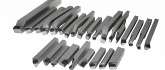
- One-piece fixtures. They are accessories for lathes made from alloy steel. Models made of tool steel are rare.
- Devices with additional plates. They are made at the factory from different types of hard alloys and metals.
- Models with removable plates. They are fixed to the holder using screws. Rarely used during serial processing of metal parts.
The main classification is the division of devices into separate types according to shape and design. We need to talk about them separately.
Classification of incisors
Direct passes
Used for external processing of steel workpieces. Dimensions:
- rectangular holders - 25x16 mm;
- square holders - 25x25.
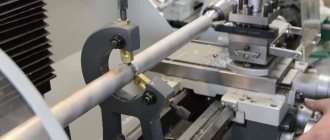
A pass-through turning cutter with a part fixed in a square-section caliper. Used when carrying out special piece operations.
Bent pass-throughs
Special equipment in which the working part is bent to the left or right. Used for trimming parts. With their help it is convenient to remove chamfers. There are three types of bent incisors:
- Training equipment - 16x10 mm.
- The most popular size is 25x16 mm.
- Custom models - 40x25 mm.
Rarely are the dimensions of the holding part 32x20, 20x12 mm.
Thrust pass-throughs
Devices come with a straight and bent working element. Designed to work with cylindrical parts. The shape plus proper sharpening allows you to quickly remove most of the excess from the working surface of the workpiece. The dimensions of the holders for thrust devices are 16x10–40x25 mm.
Bent edges
They are equipment similar to a walk-through. However, there is a difference in the shape of the cutting edge. It is triangular, which allows for better processing. The dimensions of the holding part are 16x10–32x20 mm.
Cut-off
Popular devices that are used when cutting metal workpieces. A 90 degree angle is formed at the cut site. With its help, grooves and recesses are created on parts. The cutting equipment is a holder with a fixed plate made of a hard metal alloy. The dimensions of the holding part are 16x10–40x25 mm.
Working with a cutting tool
Threading machines for external threads
These devices are used when you need to make threads on the outside of metal workpieces. The instrument consists of a holding part with spear-shaped plates attached to it.
Threading machines for internal threads
The devices are used for cutting threads in drilled holes. The device consists of a holding element with a square section. The depth to which the thread can be cut depends on its size. To use threading tools, a guitar must be installed on the industrial equipment.
Boring for blind holes
Boring tools are equipped with a working part bent on its side. A cutting triangular plate is soldered on top. The size of the hole that needs to be bored depends on how much the length of the part fixed in the caliper changes.
Boring machines for through holes
This is equipment for industrial equipment. It is used for boring holes created by drilling. The depth of machining of the holes depends on the length of the part fixed in the caliper. The element with the cutting edge has a bent head. The thickness of the material removed by the cutting edge is almost equal to the bend. The maximum length of the holding part is 300 mm.
Boring turning tools
Prefabricated
Perform various technological operations. The design allows you to attach different carbide inserts to the holder. The presence of several working elements allows you to increase the versatility of the device. The cutters, which are assembled from different plates, are fixed in the spindles of equipment controlled by a CNC system. Using prefabricated devices, holes are machined, contours are made, and grooves are selected.
Pros and cons of replacement metal plates
Carbide inserts for turning tools have more advantages than disadvantages.
- Strength. Tungsten carbide, cobalt, and titanium are used to make plates. These materials guarantee high wear resistance of the tool and stability under temperature changes.
- Saving. If the soldering of a solid cutter is worn out, the holder is usually also thrown away. For cutters with mechanically fastened carbide inserts, you only need to turn the edge, and when all the edges are worn out, replace the insert. The cutter itself lasts much longer than the replacement plate; if used carefully, it is almost impossible to break.
- Versatility. One cutter and a set of replacement inserts are enough; there is no need to buy several tools of different sizes and geometries.
- Standardized sizes and shapes. Carbide inserts are manufactured in accordance with GOST and have standard sizes and shapes, which is especially important when working on CNC machines.
- Quick replacement of dull cutting parts. Replacing a worn plate takes a minimum of time; the equipment does not stand idle, as happens when resharpening and adjusting brazed elements.
- Easy to use. The designations for turning indexable carbide inserts are easy to understand. Marking will help you understand which cutter the equipment is intended for, what materials it can process, and at what speed the machine should be set.
There is only one downside to replacement plates - they are expensive, for which there is an explanation: the products are made of high-strength alloys and have a long service life, so they cannot be cheap.
general information
For the manufacture of all models of attachments for cutters, only alloys characterized by an improved formula are used - AL 20 (40) and AP 25 (40) . The geometry of any sample is thought out to the smallest detail. This allows the corresponding technological operations to be carried out with maximum accuracy and in a short time, with a significant reduction in the percentage of defects.
Existing standards
Carbide inserts come in several types. A detailed description of each of them can be found in the relevant GOST.
- 19042 from 1980. This standard defines the designation system, categorization and requirements for the shape of carbide inserts (replaces GOST under the same number from 1973).
- 19086 from 1980. This document outlines all the characteristics of chipbreakers, as well as replaceable attachments of the supporting and cutting type.
- 25395 from 1990. GOST applies to the type of carbide inserts that are fastened to the holders of through-cutting, boring and revolving cutters by soldering (01, 61, 02 and 62).
Classification of carbide inserts
Carbide inserts for turning tools are classified according to a number of parameters.
- Tool type. Turning cutters are grooving, shaped, cutting, scoring, boring. Each tool requires different insert profiles.
- Material. The properties of carbide inserts for turning depend on the amount of titanium, tungsten and other components present in the alloy. Replaceable plates are also made from ceramics. This tooling is suitable for machining heat-resistant alloys and continuous finishing and semi-finishing of metal workpieces.
- Size. Carbide inserts are selected according to the size of the workpieces being processed.
- The size of the back angle. This parameter affects how clean the workpiece will be processed. The larger the relief angle, the cleaner the processing. Inserts with large clearance angles are usually used for cutting soft metals.
- Accuracy class. Turning replaceable carbide inserts are produced in 5 accuracy classes. With their help, products are processed with different tolerances depending on the geometric parameters of the workpiece.
Types of turning tools
There are many types of turning tools, here are the most common:
- pass-through: used to create contours of a rotating part, turning, trimming during transverse and longitudinal feed;
- boring cutter: used to create various grooves, recesses, holes. Makes holes through;
- Scoring cutter: used only with transverse feed for turning step-shaped parts and ends;
- cutting: fed across the axis of rotation, makes grooves and grooves around the part, used to separate the finished product;
- threaded: cuts threads of any type on parts with any cross-sectional shape. Threading tools can be curved, straight, or round;
- shaped: they are used to grind parts of complex configurations, take out various chamfers on the outside and inside.
Marking of carbide inserts
The marking of the carbide insert informs about the material of manufacture, shape, clearance angle, length of the cutting edge and accuracy class of the equipment. Letters and numbers in the designation are always deciphered from left to right.
Decoding the markings of a carbide insert
Each symbol in the marking indicates a specific indicator. The first letter gives information about the shape of the carbide insert, the second - about the clearance angle, the third - about the tolerances for height, thickness and size of the inscribed circle, the fourth - about the presence of a chipbreaker or hole.
The letters are followed by numbers. The first two indicate the length of the plate, the next two indicate the thickness, and the last two indicate the radius of the angles. The last two letters characterize the type of chipbreaker or its absence (in this case, None is written instead of two letters). The last designation (two letters and four numbers) indicates the alloy from which the turning replacement carbide insert is made.
Let's move on to the notation.
Plate shape
It can be completely different, from diamond-shaped with an apex angle of 35 degrees to round. Inserts of different geometries impart different properties to the workpiece.
- H - hex 120°.
- O - octagonal 135°.
- P - pentagonal 108°.
- R - round.
- S - square 90°.
- T - triangular 60°.
- C—diamond-shaped 80°.
- D—diamond-shaped 55°.
- E - diamond 75°.
- M - diamond 86°.
- V - diamond-shaped 35°.
- W - triangular 80° with an increased angle at the apex.
- L - rectangular 90°.
- A is an 85° parallelogram.
- B is an 82° parallelogram.
- N/K - parallelogram 55°.
Some forms of carbide inserts for metal
Insert clearance angle
Carbide cutting inserts are used to reduce the force applied during external and internal processing.
- A - 3°.
- B - 5°.
- C - 7°.
- D - 15°.
- E - 20°.
- F - 25°.
- G - 30°.
- N — 0°.
- P - 11°.
- O is a special angle.
Accuracy class
Implies tolerances on the theoretical diameter of the circle inscribed in the plates, thickness and other parameters. Tolerances are important to consider for inserts prior to edge preparation and coating.
Design features of the plate
Describe the shape of the plate: the presence or absence of mounting holes, the presence of one or two working sides, the presence or absence of chip-breaking geometry.
Size, thickness, radius
In the marking of the carbide plate the numbers are encrypted:
- the first two digits are the length of the cutting edge;
- the second two numbers are the thickness of the plate;
- the third pair of numbers is the radius of the rounding at the vertex.
Additional designations
Additionally, indicate the type of insert design (right, left, neutral) and the parameters of the cutting edge (sharp, rounded, chamfered).
Chipbreaker
The markings of chipbreakers vary from manufacturer to manufacturer. When choosing, you should rely on the recommendations from the catalog.
Selecting a cutting insert when machining various metals
Selecting a carbide insert for a turning tool requires taking into account the following factors.
- The material of the workpiece to be processed.
- Type of processing - rough removal, finishing and finishing pass, semi-finishing.
- Dimensions, radius and accuracy class of the plate. For example, for roughing you need to take a plate with a large radius and a small accuracy class.
- The shape and grade of the insert are suitable for the existing cutter.
- Groove and insert width (for parting and groove inserts).
- Profile, thread type, right or left hand version, thread pitch (for inserts intended for thread cutting).
Cutter with mechanical fastening
Important!
For cutters from some manufacturers, only original carbide inserts are suitable. In particular, this applies to cutting and milling products, as well as inserts for drills. Turning equipment is most often universal and compatible with holders of different brands.
Classification of turning tools
According to the generally accepted GOST classification, all metal turning tools are divided into the following categories:
- with a cutting edge made of alloy steel - the entire tool is made from a single piece of metal. They can also be made from tool steel types. Today they are rarely used;
- with carbide tipped - the working carbide edge-plate is welded to the base - the head. This is the most common type of instrument;
- with fixation of carbide plates mechanically - the cutting plate is fixed on the head using screws and clamps. Replaceable carbide inserts are made from metal and metal-ceramic materials. This is the rarest category.
There is also a classification according to the direction of the feeding movement:
- left - served from the left: if you take it in your left hand, the main working edge is located under the thumb;
- right - fed to the machine from the right: if taken in the right hand, the main working edge will be under the thumb, more common in practice.
According to the classification, based on the processing method, incisors are distinguished:
- finishing;
- rough (grinding);
- semi-finish;
- for delicate work.
