Drawing
Sheet stamping - a method of manufacturing flat and three-dimensional thin-walled products from sheet material, tape or strip using stamps on presses or without the use of presses. Sheet stamping is divided into hot and cold.Hot stamping. It is mainly used in the production of boiler bottoms, hemispheres, buoys and other hull parts for shipbuilding. They are made from steel sheet with a thickness of 3 ... 4 mm. Hot sheet metal stamping operations are similar to cold stamping operations. However, when designing a technological process, heating is always taken into account. When drawing up a drawing of a workpiece, it is necessary to take into account the shrinkage of the metal during cutting, punching and bending, as well as the degree of warping when the part cools, since its dimensions are somewhat reduced. This circumstance forces us to increase dimensional tolerances in comparison with cold stamping. Workpieces are heated in flame and electric furnaces, as well as in electric heating devices.
Cold stamping . This is the most progressive method of pressure processing, since it allows you to obtain parts that in most cases do not require further cutting. Cold sheet stamping is used to produce both large and small parts (car frames and bodies, aircraft chassis, ship trim elements, watch mechanism parts, etc.).
Sheet stamping allows for greater savings in metal usage while at the same time providing high productivity. But it gives the greatest effect in mass and large-scale production.
Cold sheet stamping uses carbon and alloy steel, aluminum and its alloys, copper and its alloys, as well as non-metallic materials: cardboard, hard rubber, leather, rubber, fiber, plastic, supplied in the form of sheets, tapes and strips.
Sheet stamping technology. The main technological equipment for the manufacture of products by sheet stamping are vibrating shears (Fig. 77), crank presses (see Fig. 87 and Fig. 88) and hydraulic presses. Sheet stamping operations can be divided into two main types: parting and forming. The main separating operations include: cutting, punching and punching.
Rice. 77
Rice. 87
Rice. 88
Cutting is an operation where sequential separation of part of the workpiece occurs along a straight or curved line. Cutting is used to obtain both finished parts and cutting the sheet into strips of the required width. When cutting a sheet, it is necessary that the output of parts from the sheet is maximum and waste is minimal. The rationality of cutting is determined based on the calculation of the material utilization rate. The coefficient is understood as the ratio of the area of the cut parts to the area of the sheet. The cutting operation is carried out using vibrating, disk, guillotine and other shears.
Vibrating shears (Fig. 77) are a machine with short knives. The upper knife 5 receives oscillatory movements from the electric motor 1 through an eccentric mechanism. The sheet metal is installed on the table 7 and moved between the upper 5 and lower 6 knives until it stops 3, which can be moved and secured in the frame bracket, 2.4 - the head, 8 - the bed stand.
Cutting is an operation to obtain a closed-loop blank (Fig. 78). In Fig. 79 shows drawing (I) and diagram (II) of a typical part made from strip by cutting.
Rice. 78
Rice. 79
Punching - making holes in a part of the desired shape (Fig. 80).
Rice. 80
The main forming operations* include bending, drawing, flanging, crimping and forming.
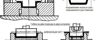
Bending is an operation in which a flat workpiece is given a curved shape (Fig. 81: 1 - punch; 2 - neutral layer; 3 - matrix): R and r - outer and inner bending radii, S - thickness of the material. It can be V-shaped, U-shaped, etc. (Fig. 82).
Rice. 81
Rice. 82
In Fig. 83 shows a drawing of a part in which the holes are made by punching. After this, the part is bent on the die.
Rice. 83
Drawing is an operation that turns a flat workpiece into a hollow spatial part or semi-finished product 2 (Fig. 84). The hood is used to produce not only cylindrical parts, but also complex-shaped box-shaped, conical and hemispherical ones. When drawing, the flat workpiece 5 is pulled by the punch 1 into the hole of the matrix 3. To prevent the formation of folds in the workpiece under compressive stress, clamps 4 are used.
Rice. 84
The hood can be without thinning or with thinning. In the first case, it occurs without a noticeable change, in the second, not only the shape of the workpiece changes, but also the thickness of its walls. In the case when it is necessary to obtain a deep drawing, it is carried out in several passes. In Fig. 85 shows a drawing of a typical part made from metal sheet 1, made by stamping with drawing.
Rice. 85
Beading is the operation of forming edges along the outer contour of a sheet blank or around pre-punched holes (Fig. 86). It is used mainly for the formation of necks in flat parts 2, necessary both for threading and welding or assembly. Usually it is performed sequentially (I, II, III) in one or several passes in dies consisting of punch 1 and matrix 3. The flanging operation is very often performed at the ends of pipes when connecting flanges to them, with the help of which the pipes will be connected in the future.
Rice. 86
Crimping is an operation of narrowing (reducing) the end part of hollow or three-dimensional parts. It is carried out by compressing the material with a stamp from the outside in a conical matrix. In this case, the configuration of the crimped part depends entirely on the shape of the die.
Molding is an operation associated with a local change in shape while maintaining the configuration of the outer contour of the part. An example of molding is the production of stiffeners on engineering parts, as well as an increase in the diameter of the middle part of a hollow part.
The technological process of processing various materials by pressure, as mentioned above, is carried out on presses. Presses are hydraulic and mechanical (crank, screw, rack and pinion, etc.). According to their purpose, presses are divided into forging, stamping, sheet-stamping, embossing, trimming, pipe-shaping, bending, straightening, briquetting (for the production of briquettes from lumpy or powdery materials), forging and stamping machines, thermoplastic machines, etc.
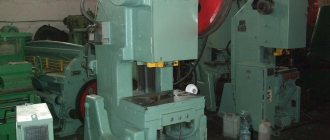
Crank hot stamping presses GOST 6809-87E (Fig. 87) are manufactured in Russia with pressures from 61.78 to 617.8 kN (mc is a unit of force and weight). They consist of a frame 1, a slider 2, a connecting rod 3, a crank shaft 4, 5 service columns, a gear 6 and a friction clutch 7. The use of presses for hot die forging is very effective in comparison with other technological equipment. They provide higher precision forgings with significant metal savings. The presence of induction electric heating in them helps to improve working conditions in the workshop: noise and shaking of the building are reduced, and smoke in production premises is eliminated. The press is controlled by regulatory bodies and with the help of compressed air from the workshop line.
Rice. 87
In Fig. Figure 88 shows a press for cold stamping GOST 9408-89E, consisting of a rack 1, an electric motor 2, a slider balancing cylinder 3, a gear 4, guides 5, a slider 6 and a press table 7. Both small and large sheet parts are produced on such presses , for example, car bodies. Possible press pressure is 30.89 kN.
Rice. 88
Hydraulic presses have the best characteristics for deep drawing and other sheet metal stamping operations, since they deform the metal at a constant speed. Such presses are widely used in the aviation and rocket industries.
In Fig. 89 and 90 show large aircraft assembly units, the parts of which are made by pressing. Thus, the floor frame of an aircraft passenger cabin (Fig. 89) includes: skin 1, frame 2, stringers 3, transverse beams 4 and continuous beams 5. And the nacelle of an aircraft turboprop engine (Fig. 90) consists of a propeller hub fairing - 1 , air intake 2, front hood cover 3, rear hood cover 4, hatch 5, power truss, casing 7, stacker 8, tail part of the nacelle 9, power frame 10, oil cooler frame 11, power frame 12 and side beam 13.
Rice. 89
Rice. 90
Progressive methods of cold sheet stamping. New types of stamping, due to their simplicity and efficiency, are widely used in small-scale and single-piece production. These include stamping with rubber, liquid, explosion, electro-hydraulic, etc.
Rubber stamping . With its help, separation and form-changing operations are carried out. In this case, the punch or matrix is rubber. Rubber stamping is most often used for products made of thin sheet metal up to 2 mm thick (aluminum, copper alloys, low-carbon steel).
Liquid stamping. In this case, the metal is deformed under fluid pressure, taking the form of a matrix. This method is used for drawing hollow parts of various shapes.
Explosion stamping . To plastically change the shape of a workpiece, explosives are also used (explosive gas mixtures of methane, propane, hydroxygen, etc.), creating high pressure, under the influence of which the workpiece takes the shape of a stamp.
Explosion stamping is used for the manufacture of large parts and parts of complex shapes, when their manufacture by other methods is impossible (for example, hard-to-deform alloys) or uneconomical. Such
stamping does not require complex and expensive equipment.
Electrohydraulic stamping . This method is characterized by the fact that the energy carrier is a high-voltage electric charge in the liquid. The discharge causes the appearance of a shock wave, which deforms the workpiece, giving it the required shape.
This type of stamping makes it possible to perform all cold sheet stamping operations with great accuracy and at relatively low cost.
Magnetic pulse molding. The formation of products by this method occurs when a pulsed magnetic field is created around the workpiece and the interaction of this field with pulsed currents flowing in the workpiece. As a result of this interaction, eddy currents are excited in the workpiece, which also leads to the formation of an electromagnetic field around it. This creates the prerequisites for a dynamic effect on the workpiece and its deformation.
This method is used to perform compression of pipe blanks, relief molding, cutting, etc.
There are other progressive methods of sheet stamping, but we will not consider them.
* Shaping operations are those by which spatially shaped parts are obtained from a flat workpiece
Fundamentals of the theory of technological processes of sheet metal stamping, forging
Drawing is a LS technological operation consisting of transforming a flat or hollow workpiece into a closed-loop hollow product open at the top. Based on the geometric shape of the resulting parts, products of axisymmetric, box-shaped and complex asymmetrical shapes are distinguished. In addition, a distinction is made between a hood with and without a clamp, as well as with and without thinning of the walls.
The drawing diagram without clamp is shown in Fig. 1.15. The punch, acting on the central part of the workpiece (Fig. 1.15a), causes its deflection by creating a bending moment from the side of the matrix and the punch. Further lowering of the punch leads to the appearance of radial tensile stresses sufficient to transfer the flange part of the workpiece to a plastic state. From this moment, the workpiece begins to be drawn into the matrix with the formation of the side surfaces of the drawn product while simultaneously reducing the diameter of the workpiece. The action of radial tensile stresses σρ leads to the fact that compressive stresses σθ arise in the flange in the tangential (latitudinal) direction. The combined action of these stresses ensures that the flange is pulled into the die hole and the product is obtained (Fig. 1.15b).
In one drawing operation you can get one shallow part, because... at high degrees of elongation in hazardous areas (transition from the flange to the wall and from the wall to the bottom), the magnitude of the radial tensile stresses may exceed the maximum σρmax, which will lead to separation of the flange or bottom from the wall of the part.
The stress-strain state in the sections under study in the case of drawing with clamping is shown in Fig. 1.16.
Section 1. The flange part is under the influence of tangential and axial compressive stresses and radial tensile stresses, that is, a volumetric scheme of stressed and deformed state is realized. Without clamping, axial stresses σz are equal to zero.
Under the influence of such a scheme of stress-strain state with the presence of a maximum value of tangential compression stresses (σθmax), loss of stability of the flange part of the workpiece and the formation of corrugations (folds) are possible. To prevent this phenomenon, a clamp or fold holder is used, when used, the axial deformation εz is significantly reduced and tends to zero, which ensures a reduction in folding due to a decrease in the thickness of the flange part.
Section 2. In this section of the transition from the flange to the cylindrical part of the product, complex deformation occurs, caused by spatial bending, the greatest radial stretch and slight tangential compression. The radial tensile stresses acting in this section are maximum and can lead to separation of the flange part of the workpiece, especially with a large clamping force Q.
Section 3. In the wall (cylindrical part) of the hollow product, a linearly stressed and plane-strained state is realized.
Section 4. The part of this rounding of the product is the most dangerous section from the point of view of the occurrence of cracks. This is caused by the action of a volumetric stress pattern of biaxial tension and uniaxial compression, under the influence of which a significant thinning of the walls in this part of the workpiece occurs. To prevent separation of the bottom from the walls, which is a consequence of the action of such a SS scheme, it is necessary that the magnitude of the radial tensile stresses does not exceed σθmax.
Section 5. The bottom of the product is in a plane-stressed and volumetric-strained state. During the first stretching transition, the thickness of the metal remains virtually unchanged, but in subsequent operations the bottom becomes significantly thinner.
Thus, during drawing, an opposite scheme of stressed and deformed states appears. The consequence of this is different thickness of the walls of the product, which can lead to three main reasons for defects during drawing: folding on the flange part of the workpiece, to prevent which it is necessary to use a clamp; separation of the flange from the workpiece wall; separation of the bottom from the wall of the workpiece.
To eliminate the last two types of defects, it is necessary to assign the amount of draft according to the transitions, taking into account the minimum permissible draft coefficients. Otherwise, the magnitude of tensile stresses is σρ. will exceed the maximum σρmax and separation will occur, and the higher the clamping force Q, the more likely the flange part of the product will be separated.
Draw force
To calculate the traction force, it is recommended to use the general formula:
Р=L·S·σρmax·k
where L is the perimeter of the part; S—thickness; k is a coefficient that takes into account the shape of the part; σρmax—maximum radial stress.
Since in all cases it is difficult to take into account the peculiarities of the process of drawing products of various geometric shapes, it is proposed to use various empirical coefficients on the basis of production and experimental data to determine the force. For example, for cylindrical parts with a wide flange, the generalized formula will be written in the form
Р= π d·S·σ·k
where σ is the tensile strength of the metal.
When calculating the pulling force of tall square boxes in the initial operations, it is recommended to use the last formula, and in the last operation the following relationship:
P=(4B-1.72rK)·S·σ·kb
where B and rK are, respectively, the width and radius of the corner curvature of the box; kv - coefficient.
Sheet stamping
Those. Sciences
24.10 1:11 363 VN:F [1.9.22_1171]
Wait…
Rating: 5.0/ 5 (1 vote cast)
303 Sergey Viktorovich
Sheet stamping is a method for producing flat and three-dimensional thin-walled products from sheet material, tape or strip using dies on presses or without the use of presses (pressless stamping). Sheet stamping is divided into hot and cold. The most widespread is cold sheet stamping. Sheet stamping operations are divided into two main classes: separation, in which one part of the workpiece is separated from another, and forming, in which complex-shaped products are obtained by deforming the metal of the workpiece without destroying it. The main separating operations include cutting, cutting and punching.
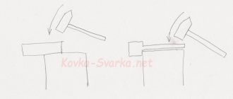
The main form-changing operations include bending, drawing, crimping, flanging, and molding (Fig. 3.32).
Rice. 3.32 Scheme of shaped sheet stamping operations; a) cutting down; b) flexible; c) hood; d) molding. 1 – punch; 2 – blank (product); 3 – stamp (matrix).
Cutting is the sequential separation of a part of a workpiece from a straight or curved line; this is a procurement operation. It is usually performed using guillotine shears.
Cutting is an operation of simultaneous separation of material from a workpiece along a closed contour, and the separated part is a product.
Punching - making holes by separating material along a closed contour inside a part. When punching, the separated part of the metal is waste.
Bending is a form-changing operation for obtaining a curved part from a flat workpiece. Drawing is an operation that turns a flat workpiece into a hollow part or semi-finished product.
The hood can be used to produce not only cylindrical parts, but also more complex shapes: box-shaped, conical, hemispherical. The drawing in one pass is regulated by the strength of the drawn cup. An attempt to pull too large a workpiece into the die results in the bottom being torn off. The possibility of drawing is determined by a coefficient representing the ratio of the diameter of the cap being drawn to the diameter of the workpiece and must be at least 0.5–0.6: d/D=0.5–0.6. If the coefficient is smaller, then the part is pulled out in two or more transitions.
Crimping is the operation of narrowing the end part of hollow or three-dimensional parts by compressing the material with a stamp from the outside in a conical matrix.
Beading and beading is the formation of beads along the outer edge of a workpiece or around punched holes by stretching the material.
Forming is an operation that changes the shape of a workpiece by deforming the material. The main equipment for sheet metal stamping are shears, crank presses and hydraulic presses. The advanced stamping method is pressless rubber sheet stamping, hydraulic drawing, explosion, magnetic pulse and other methods, which dramatically increase labor productivity and, therefore, reduce the cost of stamping.
Similar articles:
Cold die forging
Stamping on horizontal forging machines
Basic forging operations
- Stamping
Previous entry Next entry