FEATURES OF STAMPING ON KGSHP IN CLOSED DIES
LECTURE PLAN:
1. Features of stamping in closed dies.
2. Determination of the dimensions of the initial workpiece.
3. Compensators, their purpose and placement in dies
4. Design features of closed stamping dies.
Features of stamping in closed dies
In open stamping, the flash guarantees the receipt of the specified forging configuration, but, being a technological necessity, it simultaneously increases metal loss, deformation force, and requires a trimming operation. The method of stamping in closed dies (flareless stamping) is more economical, since it allows you to obtain a forging with minimal subsequent cutting processing. This method makes it possible to implement a scheme of uneven all-round compression with a significant amount of lateral compressive stress. It helps to better identify the plastic properties of metals. Closed stamping makes it possible to reduce the cost of forgings by 30...40% and significantly reduces the labor intensity of subsequent cutting processing.
When developing a forging drawing, it is necessary to change the shape and dimensions of individual elements of the part to prevent sinkage and clamps, facilitate shaping and ensure tool strength. When stamping forgings with a horizontal matrices parting plane, stamping slopes are provided on the forging surfaces parallel to the direction of the force and are taken equal to 1.5...1°. For vertical parting - on surfaces perpendicular to the punch stroke, and are taken equal to 0.5...1°. Internal slopes are 1…3°. Tolerances on the vertical dimensions of forgings depend on the accuracy of adjusting the closed height of the die space, fluctuations in the temperature of the workpiece, and the accuracy of die manufacturing and are 0.5...0.7 of the corresponding tolerances in accordance with GOST 7505. The tolerance on horizontal dimensions consists of the tolerance for the manufacture of the corresponding section of the die and the tolerance for its wear . The forging drawing must indicate the permissible dimensions of the end burr. Transition radii must be provided, the values of which are determined from the table. A slight increase in the mass of the forging is secondary compared to the improvement of forming conditions and the reduction of die wear.
Determining the dimensions of the original workpiece
When stamping in open dies, all calculation errors and workpiece cuts are compensated by the presence of excess metal going into the flash, and the accuracy of calculating the dimensions of the original workpiece is not of great importance. When closed stamping, it is very important to ensure the exact volume of the workpiece, since excess metal at the end of the deformation process can cause a significant increase in force, leading to overload of the mechanism and failure. During the stamping process, gradual wear of the die occurs, which leads to a change in the volume of the forging. If the workpiece is calculated based on the nominal dimensions of the forging, then the groove in the developed die will not be filled. Therefore, it is recommended to determine the minimum volume of workpiece using the formula:
, (1)
where is the average volume of the forging, determined by the largest horizontal dimensions (nominal + tolerance) and the smallest vertical dimensions (nominal - tolerance); -% burnout.
Thus, deviation of the workpiece volume is possible only upward by the amount of the calculated tolerance, which ensures filling of the die cavity.
The estimated dimensions of the initial workpiece are determined:
; ;
(2)
; .
To facilitate the selection of a workpiece and adjust its length depending on the actual rolling tolerance, special nomograms should be used.
In order to obtain more accurate dimensional workpieces, shear cutting is used in dies with differentiated clamping of the rod on both sides of the cut, which prevents the bending of the rod and the spreading of the knives, and reduces tool wear. In terms of quality and accuracy, this method competes with cutting with saws.
Stamping in closed dies
This process, carried out on horizontal forging machines, presses and hammers, is sometimes called flashless forging.
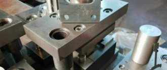
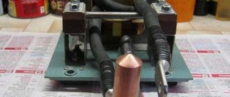
The essence of the process (Fig. 1) is that the workpiece with dimensions H0 and D0 is deformed while being in the cavity of one part of the stamp, into which the other part fits, like a guide (Fig. 1, a, 6). In this case, the stamp does not ensure the free removal of a cylindrical forging with dimensions Hk and DK from the strand. To avoid this, stamping slopes are used or forgings are removed in the following two ways. To remove the forging from the cavity, an ejector is used (Fig. 1, c). In part 1 of the die there is a rod 3, which pushes out the forging after part 2 of the die moves away (during the reverse stroke of the machine). To reduce the pushing force, stamping slopes α of relatively small sizes are used. According to this scheme, stamps are made using presses. In another case (Fig. 1, d), the part of the stamp in which the cavity is located is made detachable, consisting of two halves 1' and 1', the stamp consists of three parts and has a split in two planes; stamping slopes are not needed. According to this scheme, dies of horizontal forging machines are made, in which metal deformation usually occurs at the end of the rod. Recently, dies with a split matrix without slopes have also been used on presses when stamping dimensional workpieces.
Rice. 1. Stamping schemes in closed dies
Almost some of the metal flows into the gaps between the detachable parts 1 and 2 of the closed die, forming a slight burr, the volume of which depends on fluctuations in the volume of the workpieces due to the inaccuracy of their manufacture. Stamping in a closed die is characterized by the following features.
1. Fluctuations in the volume of workpieces should be insignificant. When stamping, no burr is provided, so the volume of metal in the cavity practically does not change: V = const.
2. The burr, often formed as a result of metal flowing into the gap at the die parting site, is insignificant, its thickness does not change during the stamping process, and the direction of flow coincides with the direction of movement of the die.
3. The macrostructure of forgings is characterized by the fact that the metal fibers receive the outline of the forging and are not cut.
Each of the described stamping methods has advantages and disadvantages, however, stamping in closed dies is more rational, since with it only an unforeseen and small burr is possible (0.5-1%), the quality of forgings is higher than those made from closed dies.
The stamping scheme in closed dies for low-plasticity alloys is especially effective. Significant lateral support of the cavity walls increases hydrostatic pressure, as a result of which the plasticity of the metal increases. A significant advantage of closed dies is that they are less demanding when it comes to shaping the workpieces; however, as in open dies, the centering of the workpieces must be ensured. The main requirement for stamping in closed dies is the accuracy of the volume of workpieces. A smaller volume of blanks than required leads to unfilled die corners and scrapped forgings. A larger volume of the workpiece due to the inability to record the moment of filling the cavity (end of stamping) leads to expansion of the die, which negatively affects its durability. When using overly large workpieces, dies are destroyed without being worn out. Increasing the accuracy of blanks is aimed at increasing the yield, which is desirable for all types of dies, not just closed ones.
The main disadvantage of the stamping method in closed dies is its non-universality and limited rational forms of stamped forgings (Fig. 2). For comparison, longitudinal sections of open and corresponding closed dies are shown, from which it can be seen that, for example, a round forging contour is unacceptable due to the small angle β and the low resistance of the die edge to: it is better if β ≥ 90°, which is not always possible. It is this circumstance that is decisive and explains why stamping in open dies is more common (closed dies account for less than 10% of stamped forgings).
However, stamping in closed dies is continuously being improved and its application is gradually expanding.
Figure 2. Cross-section of open (a) and corresponding closed (b) dies: α - die slope; β is the angle of the working edge of the inner part of the die
In order to avoid overloading of dies and equipment when workpieces enter the dies, the volume of which exceeds a certain limit, M. V. Storozhev proposed removing excess metal into a special receiver, called a compensator. The principle of the compensator design is that for each configuration of forgings and the corresponding design of the die, the place of the most difficult filling with metal is determined and a hole or slot is provided in it into which excess metal is squeezed out after the forging is formed. In Fig. Figure 3 shows the types of compensators used, the advantage of which is the ease of subsequent removal of excess metal entering the compensator. It is best if it is carried out by cutting off during the stamping process, and worse if it requires machining on machines. End compensators (Fig. 3, a) in the form of a conical receiver, as well as with a ring receiver (Fig. 3, b) are simple to make and more common than others.
Rice. 3. Scheme of closed dies with compensators;
1 - lower and 2 - upper ejectors; 3 — fixing clip; the metal entering the compensator is blackened
The internal compensator (Fig. 3, c) is used for ring-type forgings and is placed in the area of the jumper (film) in the form of a pocket of increased volume. The compensator according to the diagram (Fig. 3, d), which is designed in the form of an annular gap between the punch and the matrix, must be thin, since it is not located in the matrix itself; a place hard to reach for metal. The volume of compensated metal here is not large. The ring-type compensator is more capacious (Fig. 3, d), located between the through-type punch and the matrix in the lower part of the cavity. The original design of the die (Fig. 3, e) allows the use of a compensator in the form of an outer annular slot similar to a burr groove, but in contrast to it, the compensator has a constant slot height due to the fact that the fixing holder of the stamp, forming a metal receiver from the beginning to the end of the stamping is in the lower position.
A. 3. Zhuravlev, having studied in detail the conditions for filling the corners of closed dies, introduced their division into passive, which are located in the blind part of the cavity, and active, located in the inlet part of the cavity, between the fixed and moving parts of the dies. Metal enters passive corners, overcoming frictional forces against the side wall, which requires greater specific forces than when filling active corners. A typical location of the compensator in the blind part of the cavity is shown in Fig. 3, a, b, f. In Fig. 3d, the compensator is located in the active part of the cavity, therefore it must be narrow in order to make it difficult for excess metal to flow out and ensure that all corners of the cavity are filled. Thus, in some cases, the compensator performs the same functions as a burr groove, i.e., it inhibits the exit of metal from the cavity, but at the same time accommodates excess metal, preventing the die and equipment from being overloaded. At the same time, the die remains closed, and the dimensions of the metal receiver slot do not change during the stamping process.
Stamping in open dies
Open stamp
Stamping in open dies is different in that the die cavity remains open during the deformation of the workpiece (Fig. 11.2) and stamping is accompanied by the formation of a flash around the forging.
Rice. 11.2. Scheme of filling the die cavity with metal: a - initial stage, b - upsetting stage, c - simultaneous flow of metal into the die cavity and flash, d - filling of corners, e - additional stamping; 1, 3 - upper and lower dies, 2 - workpiece
Punching process
The stamping process can be divided into several stages. At the first stage (Fig. 11.2, a) when lowering the upper die 1, the workpiece 2 is subjected to upset between dies 1 and 3 until the metal comes into contact with the side walls of the die cavity (Fig. 11.2, b). From this moment, the second stage of stamping begins (Fig. 11.2, c), which is characterized by the simultaneous flow of metal into the die cavity and into the side gap between the dies with the formation of flash.
As the upper die is lowered further, the side gap decreases and the resistance to metal flow into the burr increases.
At this time, the flash, as it were, closes the cavity of the stamp and the metal flows into the corners that have not yet been filled and other difficult-to-fill areas of the stamp (Fig. 11.2, d). At the third stage, additional stamping occurs - the displacement of some excess metal from the filled cavity of the stamp into the flash (Fig. 11.2, d).
Technological functions
During open stamping, the flash performs a technological function - it closes the exit from the die cavity and forces the metal to fill it; in addition, it compensates for inaccuracies in the volume of the workpiece that arise during the cutting process of the latter, due to uneven waste of the metal during heating, etc. Fluctuations in the volume of the workpiece are reflected only in the dimensions of the flash, and forgings are imprints identical to the die cavity.
Requirements for blanks
Thus, the requirements for the accuracy of the initial blanks for open stamping can be reduced, which allows the use of cheaper and high-performance methods for cutting them using shear presses. On the other hand, the formation of flash leads to metal losses amounting to 20 ... 25% of the workpiece volume (and in some cases more); In addition, there is a need for an additional operation of trimming the flash in special trimming dies on trimming presses. Despite these disadvantages, stamping in open dies is currently the most common.