What is injection molding
When injection molding, a metal alloy in a liquid or solid-liquid state is fed into the pressing chamber of a special machine, from where it is pressurized at 20.
.250 MPa created by a piston moving in this chamber at a speed of 1 to 60 m/s through a thin (0.1...0.3 mm) slot feeder fills the cavity of a heated and lubricated mold and hardens in it When opened The mold casting is pushed out. Injection casting can produce complex (for example, a car carburetor body, a cylinder block of an internal combustion engine), thin-walled (up to 1 mm) castings with small (up to 1 mm in diameter) long holes, with finished threads, inscriptions, relief, knurling, and surface roughness no worse than Ra = 2.5, with dimensional accuracy up to 9th quality, with allowances for cutting 0.3. . . 0.5 mm from zinc, aluminum, magnesium and copper alloys within 0.08. . . 0.7 min.
For the first time, injection molding was used by G. Brousse in 7 in the manufacture of letters for setting letterpress forms in printing. In 1988, the first patent was received for a piston machine for pouring metal under pressure. In mechanical engineering, injection molding began to be used in 1849 for the production of small parts from tin-lead alloys. The machine designed by V. Sturzys, used for these purposes, had a manual piston drive, with the help of which a pressure of 100 was created in the pressing chamber located inside the crucible with molten metal. .150 Pa. In the 60s XIX century Die casting began to be used for the production of castings from zinc-based alloys. To increase productivity, the manual drive in piston machines was replaced by a pneumatic one. At the end of the 19th century, attempts were made to use aluminum and then copper alloys for injection molding.
In 1924, specialists from Ekkert (Germany) and Polak (Czechoslovakia) designed and manufactured machines with a cold vertical pressing chamber.
In the USSR, the industrial development of injection molding began in the 1920s. In 1923 A.F. Durnienko in Moscow, and in 1925 engineer B.Yu. Jungmeister in Leningrad organized the first production of injection moldings. In 1988, a series of ORP machines with a cold chamber located directly in the mold were produced in the USSR. In 1999 they produced a machine model LD-7 with a vertical pressing chamber.
Features of the production process
Aluminum die casting is used in production to produce parts of various sizes and shapes, as well as other castings. During the production process, molten aluminum heated to a temperature of 600˚ Celsius is fed under high pressure into a steel mold.
Press form
The main distinctive features and features of casting carried out in production workshops:
- rapid heating of the metal to the melting point;
- accurate supply of a certain amount of raw materials intended for casting;
- full automation of the production process;
- creating sufficiently high pressure to perform quality work.
All this allows us to obtain high-quality parts and components of machines and devices, manufactured with high precision and in the shortest possible time. Another distinctive feature that can be recognized as an advantage of manufacturing parts from aluminum using injection molding is high productivity with minimal labor intensity of the process.
Manufacturers take advantage of these positive qualities to create a large number of high-quality parts of various configurations intended for use in a wide variety of industrial applications.
The inherent advantage of aluminum injection molding also lies in the fact that the components of devices and other elements manufactured in this way practically do not require additional processing carried out mechanically.
To carry out all the necessary operations, the use of aluminum injection molding machines used in production workshops is especially popular among manufacturers.
These are machines equipped with a compression chamber:
- hot;
- cold.
Many enterprises widely use horizontally installed cold pressing chambers into which molten aluminum is fed under pressure.
Die casting of non-ferrous metals
Types of High Pressure Casting Equipment
Injection molding machines come with a hot (piston and compressor) or cold (piston) pressing chamber. Piston machines can have a vertical or horizontal compression chamber. Three schemes and, accordingly, three types of injection molding machines have become widespread:
- with a cold horizontal pressing chamber;
- with a cold vertical pressing chamber;
- with a hot vertical pressing chamber.
Rice. 1. Scheme of injection molding on machines with a cold horizontal chamber : a - pouring metal into the pressing chamber; b - filling the mold with metal; c - separation of the mold halves; g - pushing out the casting
In machines with a cold horizontal chamber (Fig. 1), the mold consists of a fixed 6 and movable 4 halves. The first is attached to the stationary plate 7 of the machine, and the second is attached to the movable plate 1. Molds may have channels 5 for water cooling. Rods 3 (metal) for forming cavities and holes in castings are, as a rule, located in a movable half-mold. To remove the casting from the mold, ejectors 2 are provided, which are rigidly fixed in the ejector plate.
The locking mechanism of the machine reliably presses the movable half-mold against the stationary one, after which a portion of the alloy is poured into cylinder 8, called the pressing chamber, through hole 13 and the pressing mechanism is turned on. The plunger 9 closes the filling hole and creates pressure in the chamber. The alloy fills the mold cavity through the sprue slot and hardens.
As soon as the casting hardens, the movable part of the mold, together with the casting, is withdrawn. Together with the movable part of the mold, plunger 9 moves, which pushes the press residue 10 out of the pressing chamber. The pusher plate moves along with the mold until it stops 11. The stop stops the pusher plate, and the mold continues to move. The ejectors “remove” the casting 12 from the rod 3, and it falls onto the conveyor or into the container. The mold is blown with compressed air, the working surface is lubricated, closed, and the process is repeated.
On the bed there is 1 machine with a cold horizontal pressing chamber, models 711A06. . . 71119 (Fig. 2) along the guides 3 under the action of a self-braking lever system 4 driven by a hydraulic cylinder 2, a movable plate 6 with a hydraulic ejector 5 moves. The movable part of the mold 7 is installed on this plate. The fixed part of the mold 8 is installed on a fixed plate 9 with a pressing chamber 10, into which a portion of the alloy is poured, driven into the mold by the press piston of the cylinder 11.
Rice. 2. Diagram of an injection molding machine with a horizontal cold chamber
The locking mechanism of the mold must ensure its reliable retention in the closed state. The locking force of machines with a cold horizontal pressing chamber is 1000. .35,000 kN. Often the locking mechanism is built on the basis of powerful lever self-braking systems.
In Fig. Figure 3 shows a machine model 711A08 with a cold horizontal pressing chamber with a mold locking force of 2500 kN. It has a moving plate stroke of 450 mm and a mass of the poured portion of aluminum alloy of 4.7 kg. The highest no-load speed of the pressing plunger is at least 5 m/s.
Rice. 3. Model 711A08 injection molding machine
The design of the machine provides the ability to connect an automatic manipulator for pouring metal, manipulators for lubrication of the mold and removal of castings, devices for controlling the removal of castings and lubrication of the press plunger, as well as controlling the rods installed on the movable and stationary half-molds according to a given program. The control system is implemented on a relay element base or on the basis of a programmable controller.
When using a scheme with a cold vertical chamber (Fig. 4), a dose of alloy 4 is poured into the lubricated vertical pressing chamber 5. When moving down, the plunger 3 presses on the alloy and together with it moves the heel 2 down, as a result of which hole 1 opens, connecting the pressing chamber with mold cavity. Molten metal under pressure fills the cavity. After filling the mold, the plunger rises up, and a special mechanism raises the heel 2 The heel cuts off the sprue and raises the press residue.
The CLV 100.01 injection molding machine with a vertical cold pressing chamber from VIHORLAT (Slovakia) with a mold locking force of 1000 kN is shown in Fig. 5. When removing the casting, it develops an ejector force from 5.5 to 70.75 kN with a hydraulic ejector stroke of 80 mm. Molten metal injection force from 54 to 178 kN. The injection piston stroke is 270 mm.
Up to 1.3 kg of aluminum can be poured into a feed chamber with a diameter of 80 mm. The time of one idle cycle is 6.5 s.
Machines with a vertical cold chamber differ from those previously discussed in their smaller overall dimensions, but have a longer cycle and approximately 20% lower productivity.
Rice. 4. Scheme of injection molding on machines with a cold vertical chamber : 1 - electrical cabinet; 2 — control panel; 3 - movable plate; 4 - fixed plate; 5 - power cylinder of the press plunger
Rice. 5. Vertical cold chamber injection molding machine
Rice. 6. Scheme of injection molding in machines with a hot vertical chamber
Machines with a hot vertical pressing chamber (Fig. 6) have a furnace 8 with a cast iron crucible 2, in which alloy 3 is maintained in a liquid state by an electric heater 7. The pressing chamber 6 is integral with the crucible. When the press plunger 4 is raised, the chamber is filled with alloy through hole 5. When moving downwards, the press plunger closes hole 5 in the pressing chamber and the alloy under pressure fills mold 1.
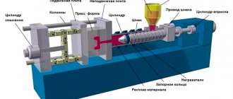
A block diagram of a machine with a hot vertical chamber is shown in Fig. 7. On the frame 1, along the guides 3, under the action of a self-braking lever system 4, driven by a hydraulic cylinder 2, a movable plate 6 with a hydraulic ejector 5 moves. The movable part of the mold 7 is installed on this plate. The stationary part of the mold is installed on the fixed plate 9 8 with a channel of the gating system for supplying molten metal. Pressing chamber 13 is connected through hole 14 to a bath of metal molten in the crucible.
Rice. 7. Diagram of injection molding machine with hot vertical chamber
When lowering the press piston 12 using cylinder 11, a portion of the alloy is driven through channel 10 into a closed mold 7-8. After the metal has cooled, the mold is opened, the casting is sent for further processing, and the mold is cleaned, lubricated, and closed. The filling cycle repeats.
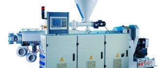
A machine with a vertical hot chamber for injection molding IPZ 300 from Italpresse (Italy) is shown in Fig. 8. Like the one shown in the diagram, it includes a furnace 1 for melting metal in a crucible 2, a press plunger 3, a high-pressure cylinder 4 for controlling the press plunger, a fixed plate 5 and other components necessary for operation.
The 713A05M machine automatically blows, lubricates and locks the mold, injects metal, waits for the casting to crystallize, opens the mold, and pushes out the casting. The weight of the poured portion of zinc alloy is 1.8 kg. The idle cycle time is no more than 3 s. It does not require the use of special filling and dosing units.
Low Pressure Casting Machines
Machines in which metal moves under the influence of compressed air are called compressor machines, or low-pressure casting machines (Fig. 9). The principle of their operation is that compressed air presses on the surface of the metal in a crucible, from which it flows through a metal pipe into the mold.
Fixed-line compressor injection molding machines have a large surface area of molten metal that is pressed against by compressed air. This leads to oxidation of the melt and does not allow the pressure to rise above 60 Pa (Fig. 9, a, b).
Rice. 8. IPZ 300 vertical hot chamber injection molding machine
Rice. 9. Schemes of low pressure casting compressor machines
Rice. 10. Structure of low pressure casting machine model ND14.10
In contrast, in machines with a moving metal wire, air presses on a small surface of the metal, which makes it possible to increase the pressure to 400 Pa and sharply reduce the oxidation surface of the liquid metal (Fig. 9, c).
The design of the low-pressure casting machine model ND14.10 from Roperwerk (Fig. 10) has a device for closing and unlocking mold halves with four guide columns for moving the upper movable plate 1, an upper movable plate for installing the upper half-mold 2, a rotary casting puller 4, cylinders fixation of the lower half-mold 5, machine table for installing the lower half-mold 6, machine base 7, furnace for melting metal 8, furnace lifting system for precise joining of the metal wire of the furnace and the mold 9. The working area is covered with a protective casing 3. This machine is made according to the scheme of a compressor machine.
Such machines are designed for the automatic production of aluminum blanks with increased strength characteristics. The control system is implemented on a programmable controller. The operating cycle of a low pressure casting machine includes:
- locking the chill mold;
- filling out the form;
- mold cooling;
- opening the mold halves and feeding the rotary casting puller;
- pushing the casting out of the mold
The machine has devices for thermal regulation of the furnace and maintaining the required pressure in it. For accurate dosing of metal during the casting process, a multi-stage injection system is used, which depends on the design of the casting. Low pressure casting machines operating according to the scheme shown in Fig. 9a, due to the significantly reduced gas segregation in the casting, have become widespread.
Pressing unit for injection molding machines
The main mechanism of the injection molding machine is the pressing unit. Most machines are equipped with pressing mechanisms that increase the pressure of the working fluid during the period after pressing, called pre-pressing. In such machines, the same battery is used to move the press piston and the multiplier piston (Fig. 11). When designing it, they try to achieve high pressing speed and minimal pre-pressing time.
Rice. 11. Pressing mechanism from Jdra (Italy)
The mechanism consists of a pressing cylinder 4, a press piston 3, a multiplier 10, a multiplier piston 11, an accumulator 7, a check valve 9, travel switches 1 and 2, valves 6 and 8, a multiplier accumulator 5 and a rod 12. The multiplier is attached vertically to the pressing cylinder , and the piston accumulator 7 is installed directly on the pressing cylinder 4. It provides the second and third phases of pressing, and the first phase is carried out by supplying liquid with a pump (arrow A). The manual valve regulator 6 adjusts the pressing speed, and the valve regulator 8 adjusts the pre-pressing time. Rod 12 allows you to control the stroke of the multiplier piston and the moment it begins to move.
Mechanisms with one battery have a simpler design, but depend on casting technological parameters. Low speeds lead to an increase in pre-pressing time, which reduces the technological capabilities of the mechanism. Mechanisms with two batteries are more complex in design, but in them the pre-pressing time does not depend on the pressing speed.
In pressing mechanisms with a multiplier, the inertia of the piston leads to an increase in pre-pressing time and increased pressure peaks during the transient process, therefore pressing mechanisms without a multiplier were developed and manufactured. They use high-pressure accumulators to perform pre-pressing. An example of such a mechanism is the pressing mechanism of the Fries company (Germany) (Fig. 12).
In the first phase, liquid from the accumulator 5 through valve 7 through channel 8 is supplied to the piston cavity of the pressing cylinder 1, causing the press piston 11 to move slowly. The speed of the press piston in this phase is controlled by valve 7. This phase continues until the rear end of the press piston 11 opens channel 9. After this, the second pressing phase begins, which continues until the chamber is filled with metal. Upon command from the limit switch, valve 6 opens and the press piston begins to move rapidly. To regulate the pressing speed in the third phase, valve regulator 6 is used
The limit switch, which is adjusted depending on the path of the press piston 11, turns on the fourth phase - pre-pressing. At this time, valve 2 opens and liquid from the high-pressure accumulator 3 enters the piston cavity of the pressing cylinder.
Rice. 12. Pressing mechanism without multiplier
Check valves 10 and 4 close, and high-pressure liquid from accumulator 3 is transferred to the piston cavity of cylinder 1, performing pre-pressure. The multiplying pressure is regulated by changing the pressure in the accumulator 3; the valve regulator 2 is used to adjust the pre-pressing time.
The mechanism has all the disadvantages that mechanisms with the inclusion of a pre-pressing device along the path of the press piston have.
Injection molding machines most often operate in semi-automatic mode. Additionally, the following operations are mechanized and automated:
- lubrication of molds of the pressing chamber and machine;
- heating or cooling of half-moulds;
- removing the casting and transporting it from the machine to the trimming press;
- feeding a portion of liquid alloy into the pressing chamber (pneumatic, magnetodynamic or mechanical manipulator);
- replenishing the crucible with liquid metal (for machines with a hot pressing chamber);
- installation of reinforcement in the mold.
These measures should increase the speed of the machine and reduce the percentage of defects. Separate kits for automation of injection molding processes are manufactured by Kuzlitmash OJSC (Pinsk). Automation can reach such a level that the machine becomes an automated complex.
The main means of automating injection molding processes is the use of molten metal dispensers, which can be of several types:
- pneumatic;
- mechanical rotary;
- mechanical on monorail
Variety and use of alloys, required machines and molds
Products made of aluminum alloys are in high demand:
- Silumin is an alloy of aluminum and silicon. After adding magnesium to its composition, the final product becomes extremely durable. This is one of the most low-shrinkage and highly airtight alloys. It is not subject to cracking during manufacture and is used to create elements subject to light loads.
- In order to create shaped castings, an alloy is used, which, in addition to aluminum itself, includes copper, silicon and iron. This workpiece is perfectly separated from the mold and is highly durable.
- When creating high-strength elements, an aluminum alloy with the addition of silicon, nickel, copper and zinc is used.
A particular alloy is selected depending on the tasks to be performed by the manufactured parts and the loads that the finished elements will have to withstand.
All operations are carried out on specially created equipment, which can be used both in a production workshop and in a small private workshop.
Using special equipment for aluminum casting, you can create items necessary in everyday life and parts that are very important when assembling various machines and units.
To create the above alloys, it is necessary to use machines equipped with both cold and hot chambers designed to melt the metal. Machines with hot chambers are necessary in the production of alloys containing zinc. The molten metal is introduced into the internal space of the mold gradually. He fills out the entire form.
When working with alloys that contain magnesium and copper, castings are produced due to the fact that the molten composition is introduced into the mold under fairly high pressure. Its level in certain situations reaches 700 MPa. It is this production method that makes it possible to significantly increase labor productivity without increasing the labor intensity of the process, and parts manufactured in this way do not require mechanical processing.
The choice of equipment when creating a workshop or organizing a casting process is based on the characteristics of the technological process. When casting aluminum under pressure, it is as follows:
- In a hot furnace, the metal is heated to the melting point and turns into a liquid state.
- At this time, a special mold must be prepared in the workshop, the internal contour of which fully corresponds to the parameters of the future part.
- Molten metal is fed under high pressure into a prepared mold.
- After cooling, the finished product is removed from the split mold.
Aluminum product in a mold
Today, some manufacturers use other casting methods. This can be casting into earth, sand or cement, but aluminum injection molding makes it possible to obtain a product with a minimum wall thickness of less than a millimeter. And everything can reach from 4 to 12 kg.
Injection molding machine dispensers
Pneumatic dispensers for aluminum alloys models 46141, 4699, 46153 (UE "Institute BelNIIlit") operate on a principle similar to that used in low-pressure casting machines, when compressed air presses on the surface of the molten metal and displaces it into the feed tray into the chamber pressing of a casting machine (Fig. 13) These machines can dose metal weighing from 4 to 70 kg in a time from 5 to 30 s, while allowing an error of no more than 3%. This dosing unit includes a melting furnace, pressure pumps and an automatic dosing device.
Rice. 13. Pneumatic dispenser model 46141 for molten aluminum produced by the BelNIIlit Institute Unitary Enterprise
Rice. 14. Gauss model CAM metal dispenser for Italpresse injection molding machines : a - general view; b - operation diagram; 1 - longitudinal guides; 2 — vertical guides; 3 - ladle; 4 — dispenser drive; 5 - injection molding machine; 6 — pressing chamber; 7 - crucible with molten metal
In Fig. 14 shows a general view and operating diagram of a mechanical monorail-mounted dispenser model CAM from Gauss, installed on Italpresse injection molding machines.
During operation, the ladle is immersed in the melt and the metal is transferred to the opening of the pressing chamber of the injection molding machine, where it is tipped over. Such dispensers can also be used to automate centrifugal casting machines.
915
Aluminum casting at home
When casting aluminum under pressure in a small workshop, similar technological features are used with some modifications. In everyday life, the melt is poured into prepared molds.
Preparation for the process
To maintain stability when casting metal, it is recommended to follow some rules:
- Make your own unit for melting the workpiece.
- Assemble a mold into which the alloy will later be poured.
The aluminum casting process itself consists of several stages:
- cleaning raw materials from contaminants, cutting them into specific pieces to speed up melting;
- heating the metal to a critical value, removing slag from the surface;
- pouring material into a mold.
Features of mold production
The production of thick-walled castings is the initial stage before direct casting. In everyday life, alloys are produced by closed and open methods.
Materials for casting molds
The following materials are used for the manufacture of special forms:
- Earth containing silicon is placed in a prepared container in layers, while compacting it. A layout corresponding to the part that will be cast is installed in the gap.
- Sand combined with liquid glass.
- Cement in solution with fluid used in brake systems.
- Gypsum mixtures.
Closed form
This type of molding is used to produce blanks of complex shapes with high quality. In this case, the form consists of two components on which the future silhouette of the part is made.
Closed form