Basic definitions
A countersink is a special cutting tool that allows you to make canonical or cylindrical holes. It is used to process finished holes in order to chamfer the center hole.
A countersink is a tool consisting of a certain number of blades designed for cutting. Designed to improve the quality of the hole and expand existing holes, creating holes of cylindrical or canonical shape. Machining holes using a countersink is called countersinking . Countersinking refers to semi-finishing metal processing.
You can come across the wrong concept when they say that a countersink and a countersink are the same thing. Using a countersink, the technical quality of the hole is improved. And it is not intended for making recesses.
Countersinking holes - removing chips or irregularities from a drilled hole. Countering holes is the process of deepening a canonically shaped hole in order to hide the head of a bolt or self-tapping screw. You can also come across the definition of hiding a self-tapping screw in a pattai.
Countersinking a hole
Countersinking of holes - processing of drilled holes for the heads or heads of bolts, screws, hardware.
Countersinking and countersinking, the difference between the processes
Distinguish the multitude. It’s easier to say that the procedures are the same. Basically, that's where we'll start. Both processing options are driven from the same source. A motor with a shaft, a machine, a device – it doesn’t matter. The main thing is the supply of torque. At the same time, there are a lot of differences in the type of impact on the surface. Let's start in order.
The countersink is designed for cleaning. This is a tool that removes all irregularities and brings holes to perfection. He polishes it and gets rid of the mustache. It also affects its overall shape. That is, the rod is usually larger than the groove. And he can make it larger, align it along the edges, give it a geometric shape.
This is how a countersink differs from a countersink; the difference mainly concerns the fact that the device itself does not affect the structure of the connector in the second type of processing. He only chamfers at first or makes a small indentation. So that when we screw the bolt there, for example, it doesn’t go completely into the surface, along with the head. And on top it was possible to install a new covering without openings.
It is also worth remembering that the processes have completely different stages. More precisely, the first type of work has its own stage. Immediately after drilling, before reaming, you need to align the groove along its entire symmetry and get rid of wall defects. And in this form, move on to the next stages. But, in fact, the operator can make a cut along the head at any time when it is convenient for him. Although it is best to do this after the final processing of the hole. To accurately represent its volumes. Yes, it is logical to carry out the countersinking of the chamfer at the end.
The mechanism of this action itself is as follows:
- First you need to completely measure the hat, which you will have to hide later. And here it is important to identify both the usual dimensional aspects - height, width, and more specific ones, such as bevel. Usually it is present if the fastener itself is, in principle, designed to be hidden.
- Select a cutting tool that accurately matches the dimensional aspects. Place it in a machine or other device.
- Fix the object with the groove, identify the correct axis point. An error of any percentage will lead to the fact that the cover will simply “fall off” the mark.
- Set the required speed. Either use standard regulations in production, or calculate the speed yourself, based on the hardness of the metal.
- Turn on the equipment and perform the operation.
Types of countersinks
Countersinks and countersinks are used to process holes or create recesses of canonical shape. In different conditions, the holes being machined may have different parameters. They are performed using varieties of countersinks or countersinks. Let's figure out what types of countersinks exist:
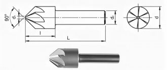
- Conical. In this countersink, the knives are located at an angle from 30 to 120 degrees and the center to the edges.
- Cylindrical. They have a cutting edge around the circumference of the cylinder, resulting in smooth cylindrical holes
- End countersinks.
Using a countersink it is possible to perform the following actions on a hole:
- Machining a hole to create a cone
- Obtaining a conical recess for self-tapping screws or other fasteners.
- Removing chamfers and chips from holes.
Countersinks are made of alloy or carbon steel for tool purposes.
Countersinks, countersinks, counterbores, reamers. Plumbing |
Countersinks (Fig. 3.34, a) are designed for processing holes in workpieces obtained by casting, stamping or pre-drilling. Unlike a drill, a countersink has a larger number of cutting edges (three or four), which ensures surfaces with higher accuracy and roughness.
By design, countersinks are mounted and solid and can have a different direction of the spiral angle (right, left, straight). Countersinks are made of high-speed steel or equipped with plates made of hard alloy grades VK6, VK8, BKbM, VK8V, T5K10, T15K6. Carbide plates are fixed in the countersink using soldering or wedge fastening, which allows the countersink body to be reused. The working part of countersinks made of high-speed steel has a reverse taper (towards the shank) of the order of 0.05... 0.1 per 100 mm of the length of the working part and is connected to the shank in the same way as with drills, by a neck. Solid countersinks are fixed directly in the conical hole of the machine spindle, and attachment ones are installed on a special mandrel, which also has a conical shank for installation in the machine spindle.
Multifaceted carbide plates are used as the cutting part of mounted countersinks. The fastening of such plates in the body of the mounted countersink is carried out mechanically (Fig. 3.35). The cutting plates 1 are fixed in the housing 2 using a rod 3, which makes it possible to replace the plates directly on the machine. To do this, it is enough to move the rod 3, rotate the plate with the next edge or replace it with a new one, fasten the rod again and continue working. The ability to equip such countersinks with plates made of various tool materials can significantly expand the technological capabilities and productivity during countersinking.
The geometric parameters of the cutting part of the countersinks (see Fig. 3.34, b) are selected depending on the processing conditions: leading angle f = 30... 60 rake angle y = 3... 30 ° for countersinks made of high-speed steel, for countersinks equipped with hard plates alloy, this angle ranges from 5 to -5°; clearance angle a on the main cutting edges is 8... 15 The choice of countersink design and material of the working part largely depends on the material being processed and the parameters of the hole being machined:
• countersinks made of high-speed steel, having three to four teeth and a diameter of 10 to 40 mm, are used for machining holes in workpieces made of structural steel;
• countersinks equipped with hard alloy plates, having three to four teeth and a nominal diameter of 14 to 50 mm, are used when machining holes in workpieces made of difficult-to-cut and hardened steels;
• countersinks with mounted heads made of high-speed steel with a nominal diameter from 32 to 80 mm are designed for processing holes in workpieces made of structural steel;
• countersinks are used for processing blind holes in workpieces made of cast iron and non-ferrous metals;
• for processing blind holes with a diameter of 15 to 25 mm, a special countersink is used, in which a special hole is made in the body for supplying coolant to the cutting zone (Fig. 3.36).
Wear of countersinks (Fig. 3.37) occurs along the rear surfaces, where areas with a rear angle equal to zero and width h4 are formed; along the front surfaces with the formation of a hole; along the ribbon with the formation of transverse grooves along the length Ll; along the corners to form conical or cylindrical sections hy. As a criterion for the wear of countersinks when processing steel workpieces, the countersink wear at the corners is equal to 1.2 ... 1.5 mm, and when processing cast iron workpieces - 0.8 ... 1.5 mm. Sharpening and regrinding of worn-out countersinks is carried out, as a rule, on special equipment in sharpening shops.
Countersinks and counterbores
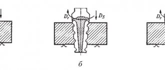
Countersinks and counterbores (Fig. 3.38) for processing supporting surfaces for mounting screws, unlike countersinks, have cutting teeth at the end and guide pins, which provide the desired direction of the countersinks and counterbores during processing. The pin is inserted into a pre-drilled hole, and the axes of the hole and the recess formed by the countersink coincide. Countersinks for processing holes for cylindrical screw heads are manufactured with a cylindrical and conical shank. Countersinks with a cylindrical shank (Fig. 3.38, i) are available with a diameter of 15; 18; 20; 22 and 24 mm: and countersinks with a conical shank (Fig. 3.38, b) - with a diameter of 15; 18; 20; 22; 24; 26; thirty; 32; 33; 34; 36 and 40 mm.
Countersinks for processing conical recesses with angles of 60, 90 and 120° (Fig. 3.38, c, d) are made with both a cylindrical and a conical shank. Countersinks with a cylindrical shank are made with a diameter of 8; 10; 12; 16; 20; 25 mm, and with a conical shank - diameter 16; 20; 25; 31.5; 40; 50; 63 and 80 mm.
To trim the ends of bosses and bosses in cast body parts, single- and double-sided castings (Fig. 3.38, e, f) made of high-speed steel or equipped with hard alloy plates are used. They are mounted on special mandrels using a bayonet lock. Counterbores with a diameter of 25 are produced; 32; 40; 50; b3; 80 and 10C mm.
Sweeps
Reamers (Fig. 3.39) are made solid and mounted with a conical and cylindrical shank, equipped with insert knives, soldered carbide plates, or made of high-speed steel. Reamers, unlike drills and countersinks, have a larger number of cutting edges, which allows, during processing, to remove a layer of material of small thickness, amounting to tenths and even hundredths of a millimeter. Allowances for reaming are selected from tables depending on the diameter of the hole being processed. There are reamers for manual and machine reaming, cylindrical and conical. Reamers for manual reaming have a square part at the end of the cylindrical shank, on which a knob is installed to rotate the reamer in the hole being machined.
Structurally, a reamer for manual reaming consists of a working part, a shank and a neck. The working part of the cone includes a cutting part (a sampling cone and a guide cone, which ensures centering of the reamer in the hole) and a calibrating part, which ensures the production of a hole with a given accuracy and roughness of the machined surface.
The cutting part of the intake cone of the reamer has an apex angle of 2°. For processing ductile metals, this angle is 12... 15°, and for processing brittle and hard materials - from 3 to 5°.
Carbide reamers have an apex angle of 30...45. The guide cone of the working part of the reamer is located at an angle of 45 oe to its axis. The clearance angle a on the cutting part ranges from 6 to 15°, on the calibrating part this angle is usually zero, and the clearance angle y is 0... 15. For brittle materials, the rake angle is zero, and for carbide reamers it ranges from 0 to -5°. Manual reamers are used, as a rule, when processing holes with a diameter of 3 to 50 mm in materials of low hardness (structural steels, non-ferrous metals). Conical reamers (Fig. 3.40) are used to ream conical holes and, as a rule, work in a set of two or three pieces.
Machine reamers are cylindrical and conical, mounted and solid. Solid machine reamers are designed for processing holes with a diameter of 3 to 100 mm, and for reaming holes with a diameter of 25 to 300 mm, attachment reamers are used. Both solid (Fig. 3.41, a, b) and mounted (Fig. 3.41, c, d) reamers are made of high-speed steel or equipped with carbide plates. The design and material of the machine reamer is selected depending on the nature of the work performed, the material of the workpiece being processed and the requirements for the quality of the machined surface.
dlja-mashinostroitelja.info
Design features
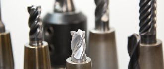
If we look at the countersink, we can highlight some of its parts
- Cutting part. This is the main part that performs the countersinking process. Consists of several cutting edges located at an angle from the center to the sides.
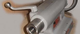
- Shank. Using a shank, the countersink is secured in the tool or machine in which the work will be performed. The shank can be tapered or cylindrical.
- The part between the shank and the cutting part has a particularly thin shape in one place. This part acts as a fuse. If the countersink gets stuck, in order to avoid serious consequences, it is in this part of the countersink that it breaks.
The structure of a countersink
One of the varieties of a countersink has welded blades on the working part, which makes it possible to process hard metal alloys.
Rules for working with a countersink
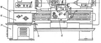
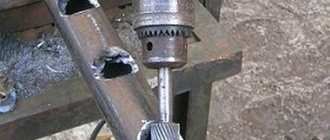
When performing work on a lathe or drilling machine with a countersink, you need to remember and follow a number of simple rules. Before starting work, check the condition of the chuck on the machine. After all, if the cartridge is in a faulty condition, it will not be possible to secure the countersink well, and thus you will not be able to get a high-quality machined hole. Countersinking of holes is carried out in accordance with the following rules:
- To perform the work, the countersink must be strictly in the center of the hole being machined.
- When processing hard metals such as cast iron, you need to take breaks from work and use special solutions to remove heat. In everyday life, technical oil is used for such purposes.
- When operating, do not exceed the speed specified by the manufacturer. Failure to comply with this rule will result in rapid wear of the cutting edges due to heating.
- Select the correct countersink diameter for the hole being machined. If you choose the wrong size, the processing will not be of high quality, namely incorrect centering, uneven edges.
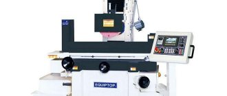
Areas of application
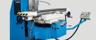
The areas of application of countersinks include use on machines such as: - lathes; — drilling; — milling; — boring; — turning-turret; — aggregate. In terms of the level of purity, the countersinking procedure, as a technological process, is classified as semi-finish processing. It is usually used before drilling holes in blank elements made of various materials. Carrying out such a technological operation must be performed at low machine speeds. Some types of countersinks are also used for processing and chamfering holes that are located in hard-to-reach places - these are reverse-type tools.
Countersink
Countersink
Metal processing by countersinking is similar to drilling - this is the rotation of a countersink around its axis. When countersinking, the hole is improved to 9-11 accuracy grades. Also, with the help of a countersink, the roughness of the hole is improved to Rz 2.5 microns.
Main purposes of the countersink:
- Calibration of ready-made holes for fasteners (bolts, studs)
- Improving hole quality before tapping or using a reamer.
Countersinking is not done using a conventional drill or any other manual method. After all, the purpose of this operation is aimed at improving the quality of the hole, which is almost impossible to do with a drill. Therefore, countersinking is performed using a machine tool using drilling, turning, and milling machines.
If we divide countersinks into groups, then in metalworking there are two groups according to accuracy:
- Countersink number 1 - Mainly used for semi-finishing as preparatory work before reaming or cutting threads.
- Countersink with number 2 - Used for final work. Has a relatively high accuracy class H11
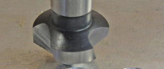
According to the design, two types of countersinks are used - solid and mounted (disassembled). If we talk about solid ones, they are used more often, and they have a cone-shaped end. It has a groove for chip removal and cooling and cutting teeth. If we talk about mounted countersinks, their design is distinguished by a removable tip, which is attached through an internal hole.
There are also countersinks that are used much less frequently, in special cases. Namely, these are countersinks with welded plates made of the hardest metal, welded or prefabricated countersinks.
The material from which the countersink tip is made
In solid countersinks, P18 or P19 steel is used to make the cutting teeth. If a countersink is made for processing carbide metals, then its teeth are made of metal-ceramic alloys VK4, VK6 or VK8. If steel products are to be processed - T15K6
The difference between countersinking and related operations
We have already found out that this stage occurs after drilling and before deployment.
But the initial stage is not always drilling. Sometimes the first stage is considered to be casting or stamping. In this version there may be even more defects. Various sagging, layering of metals, beveled walls, serious rough protrusions and the like. Accordingly, it will definitely not be possible to finish the surface for a final look in one stage. It is worth understanding that deployment is already a finishing process; it cannot cope with serious defects. Doesn't fit the shape. Countersinking will almost always raise the accuracy class to level 5. If the work is done using high-precision equipment, and it is also performed by professionals, then class is achievable. But unlike drilling, the process is longer. You will have to perform almost twice as many tool movements.
The most important difference from drilling and reaming can also be the level of permissible roughness after processing and quality, that is, the degree of compliance of the resulting part with the original parameters in the drawing or diagram. The first stage - drilling usually leaves a “whisker” of 20 microns, and the degree of accuracy can reach up to 12. After grinding with a countersink, the surface will be cleaned to 2-3 microns, and the quality will increase to 9. Finishing brings the hardware to full readiness. The roughness drops to a threshold value of less than 1 micron, and the degree of accuracy is around 6.
That is, the differences are clearly visible. This includes the degree of quality, duration, and sequence. But if you compare a countersink and a countersink, the difference will be even more obvious. After all, these are, in principle, actions from different spheres.