Drilling
As you might guess, before machining a hole you need to do something to make it. So, the most common and common method of making holes is drilling.
Drilling is a type of machining for the purpose of forming holes, performed with a drill. This process can be “manual” (as you might guess, it is done with hand tools), as well as “machine” (performed on special machines).
Typically, to make a hole less than twelve millimeters in not particularly hard materials (such as structural steel, non-ferrous metals and alloys made from it, as well as polymer alloys), hand-held drilling devices are used.
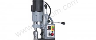
And in order to make holes larger than 12 millimeters or to improve productivity in the case of mass production, the drilling process takes place on stationary or desktop drilling equipment (machines). The first ones are vertical or radial drilling.
Tool used
The finishing of the hole is done with a special tool, a “reamer”, manually, on a drilling or lathe. It is subdivided:
- Depending on the installation location, manual and machine.
- The shape of the hole is cylindrical and conical.
- Depending on the type of fixation in the cartridge - tail and attachment.
- According to the location of the cutting edges - with uniform and
uneven. The latter make it possible to impart different degrees of roughness to areas of the treated surface. Manual reamers differ from machine reamers in that they have elongated cutting teeth and a square shank for installation in a driver. The tool, designed for drilling machines and electric drills, allows you to machine deep holes thanks to its short working part and long neck. The shank has a cylindrical or conical shape.
Reaming
Hole drilling is a subtype of conventional drilling. At its core, it is an expansion of the size of the hole made earlier. Drilling holes is also done with drills.
Advice: It is highly not recommended to try to drill holes formed not by drilling, but by other methods, such as stamping. The reason is that such holes differ in the different hardness of the material of the internal walls.
During casting, scale is formed. During forging and stamping, non-uniform internal stress occurs in different places of a metal workpiece. This results in the drill being subjected to constantly changing loads during machining. And this can cause a displacement of the drill axis or even breakage.
If you process holes using a similar method (drilling and reaming), you can achieve X quality (accuracy measurement). The roughness after drilling at the hole walls is possible within the limits of no more than Rz 80.
Manufacturers of metal cutting tools
Conventionally, the market for metal cutting tools is divided into 3 segments.
- Asian manufacturers. First on the list of exporting countries is China. Product characteristics meet the requirements of our standards. Prices are below average. This determines the high level of popularity of Chinese instruments. But, having bought a batch, you may encounter a large number of defects.
- European brands. The main offices and factories of top companies are located in Germany, Italy and France. The quality of EU instruments is at a high level. Marriage is rare. It is in Europe that the most reliable and durable tools are produced, coated with regular and aluminum-alloyed titanium nitrides (markings: TiN and TiAN).
Photo No. 15: Bosch drills coated with titanium nitride
- Russian manufacturers, as well as companies from the former CIS countries. Their products satisfy the needs of most consumers. Prices and quality are at the optimal level.
By the way, we ourselves are one of the manufacturers of metal-cutting tools. Our brand is SEKIRA.
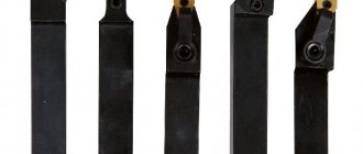
Photo No. 16: SEKIRA drills
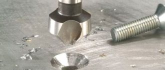
Countersinking
The name “countersinking” was used to describe mechanical processing by cutting previously made holes. Its main purpose is to give the hole the desired shape and get rid of various defects, as well as increase accuracy (up to the VIII grade), reduce the roughness index (Ra 1.25 or less).
If the hole is not particularly large, then similar processing is done on a regular table-top machine, but if you need to process a larger hole, then it is easier to do it using special equipment on the foundation.
Separately, we note that there is no point in using manual equipment. It is simply impossible to achieve the desired indicators with it.
Countersinking has 2 subtypes, such as countersinking and countersinking.
When countersinking holes, you need to adhere to a number of rules:
- Drilling and countersinking are performed during one approach. Countersinking must be done after completion of drilling work, without removing the parts from the machine fixtures. In fact, during one “approach” the part is processed with two tools.
- When countersinking holes that have not been processed in housing parts, the part must be securely and firmly fixed.
- When choosing the size of the allowance, be sure to do this according to special tables.
- Countersinking must be done in the same operating mode of the machine as drilling in front of it.
- Labor safety rules must be observed similar to those used during drilling.
Laser hole punching
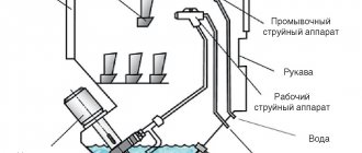
Lasers are beginning to be widely used to produce small diameter holes. This is due to the possibility of producing holes with a diameter from tens of micrometers to several millimeters of significant depth (up to 50 diameters) with high productivity and accuracy in any metals, alloys and ceramics. Laser perforation of holes has found wide application in the manufacture of gas turbine engine parts.
The main indicators of laser drilling depend on the equipment used and the material being processed and can vary widely. During laser drilling, material is removed in the form of a mixture of melted and evaporated particles, the ratio of which depends on the properties of the material and the intensity of laser radiation. Most often, processing is performed with a “pack” of laser pulses.
Laser drilling can produce a variety of hole shapes in a variety of materials, including difficult-to-cut superalloys used in aerospace applications. It is possible to drill holes at small angles to the surface. The high productivity of this method ensures the production of hundreds and thousands of holes in one part. For laser drilling in metals and alloys, pulsed Nd:YAG lasers are usually used, and in non-metallic materials, CO2 lasers are used.
Rice. 7. Laser drilling schemes: a - piercing with a single pulse; b - pulse firmware; c - trepanation; g - screw “drilling”
Depending on the size and shape of the holes, as well as the type of equipment used, various technological methods are used ( Fig. 7 ): - flashing with a single pulse; — pulse firmware; - trephination (contour cutting); — screw “drilling”; — firmware for the mask.
Firmware is performed with one or multiple laser pulses, and it is necessary to ensure high power density. The dimensions of the focal spot, depending on the hole diameter, are df = 0.05...0.75 mm.
For laser firmware, lasers with a power of 100...400 W are used. The pulse duration is selected based on the required hole quality. It should be borne in mind that reducing the pulse duration reduces its energy. Typical pulse durations used for laser drilling are in the range of 0.5...2 μs, however, there are installations that operate with pulse durations of several tens of nanoseconds. It should be borne in mind that reducing the pulse duration sometimes improves the quality of the resulting holes ( Fig. 8 ). The selected pulse frequency must provide an optimal balance between productivity and processing quality. When flashing, it is assigned within 5...20 Hz from (Nd:YAG lasers) to 1000 Hz (CO2 lasers). The pulse energy depends on the diameter of the hole being machined, the thickness and type of material. As it increases, productivity increases, but the quality characteristics of the hole decrease.
Rice. 8. Features of hole formation during processing with pulses of various durations
The size of the focal spot determines the diameter of the hole being machined. When piercing thin materials (up to 1 mm), it is set equal to the diameter of the resulting hole. The thicker the sheet being stitched, the longer the required focal length of the lens. Typically it is 100...250 mm. The focal point can be located on the surface of the workpiece, above or below it, depending on what effects are required to be provided. Most often, the focal point is set below the surface at a distance corresponding to 5...15% of the material thickness. The best position of the focal point is usually determined experimentally, based on the best quality of the resulting hole. Processing accuracy decreases with increasing laser wavelength. The latter also affects processing productivity ( Fig. 9 ).
Rice. 9. Effect of laser radiation wavelength on the volumetric rate of material removal
When assessing the quality of hole processing, its accuracy, surface roughness, shape, taper, the presence of microcracks and burrs, and the size of the heat-affected zone are taken into account. As with laser cutting processes, an assist gas is often used to help remove molten material from the hole being cut. The number of pulses required for piercing depends on the depth of the hole being machined, the required accuracy and the quality of its surfaces.
Typical defects in holes produced by piercing are traces of metal spattering at the entrance to the hole, taper and other shape distortions, the presence of melting and thermally affected zones, microcracks and other defects caused by crystallization of the material, thermal stresses and interaction with the environment.
To combat metal spattering, special coatings are used. The taper that occurs during laser piercing is quite difficult to eliminate. For these purposes, techniques are used in which, during the piercing of holes, the parameters of the pulses are changed (SPDPC method), for example, their energy is gradually increased. The effectiveness of these measures is illustrated in Fig. 10 .
Rice. 10. Typical microphotographs of holes after laser piercing using traditional technology (a) and using a protective coating and the SPDPC method (b)
In Fig. Figure 11 shows typical dependences of the hole depth obtained per unit pulse and its diameter on the laser radiation intensity.
Rice. 11. Effect of laser radiation power density on the depth of the hole pierced by a single pulse (a) and the diameter of the hole (b). Processing of copper with a laser with a wavelength of 355 nm, pulse duration 50 ns with a focal spot diameter df = 4.5 µm
When machining multiple holes, a technique called Fire-On-The Fly is sometimes used, in which pulses from a stationary laser are applied to the part as it rotates or otherwise moves, and the pulses are synchronized with the movement of the part to ensure that the beam precisely hits the hole locations. . By software changing the focus position, the power of the number and shape of the pulses, you can control the size, taper and quality of the resulting holes. The advantage of this technology is that it reduces the size of the heat-affected zone and the likelihood of microcracks. In Fig. Figure 12 shows a part with many holes obtained using Fire-On-The Fly technology. The piercing speed in parts with a thickness of ~1 mm is up to 50 holes per second. The second technique - trephination is usually performed by moving the laser beam along a given contour. The processing is carried out similarly to laser cutting with a preliminary starting hole in the center and then the beam extending beyond a given contour and moving along it. The term “drilling” instead of “cutting” is used in cases where the diameter of the hole being machined is less than its depth (thickness of the part). By changing the inclination of the beam and the trajectory of its movement, you can control the shape and size of the hole both in the section perpendicular to the axis and in the axial one. It should be noted that the accuracy achieved by trepanation techniques is higher than with piercing. Trephination is usually used to produce holes larger than 0.5 mm in diameter.
Rice. 12. Laser drilled holes using Fire-On-The Fly technology
Screw drilling is a relatively new technology for laser processing of holes, which can significantly improve their quality. Unlike trephination, a hole is obtained through several passes of the laser beam. Screw drilling, compared to piercing, makes it possible to obtain holes of a more regular shape ( Fig. 13 ), and when using nanosecond lasers, it can significantly reduce the size of the fused layer. This technology produces holes with a diameter of 100 microns. In addition, you can process holes other than round ones. Screw machining is especially effective in cases where the diameter of the hole being machined is close to the diameter of the focal spot.
Rice. 13. A hole in 1 mm thick steel produced by screw drilling with an Nd:YAG laser with a pulse duration of 10 ns (Friedrich Dausinger)
Using stitching with focusing on the mask, holes of any shape are stitched ( Fig. 14 ).
Rice. 14. Holes obtained by mask-focused piercing in a stainless steel plate 0.3 mm thick
Rice. 15. Laser stitching of shaped holes on the mask: 1 - laser; 2, 4 — elements of projection optics; 3 — mask; 5 — rotating mirror; 6 — focusing lens; 7 - detail
The diagram of such firmware is shown in Fig. 15 . In this case, a mask with a hole of the required shape is installed in the path of the unfocused beam. After focusing on the surface being processed, the focal spot has the shape of a hole in the mask, reduced by D times. Beam scaling is determined by the expressions:
(1/u) + (1/s) = (1/f) and D = (u/s) ,
where and is the distance from the mask to the focusing lens; s is the distance from the focusing lens to the surface of the part; f is the focal length of the focusing lens.
To perform laser drilling operations, special machines are produced that differ in the purpose and power of the laser used. For example, the 400W JK704 has an autofocus system and processes holes with an accuracy of ±0.025mm. It pierces a ø0.5 mm hole in 24.5 mm thick steel in 90 seconds, and the same hole in a 1 mm thick nickel alloy in one second.
Installations are available for producing very small holes on parts up to 1 mm thick. They can produce holes with a minimum diameter of 15 microns. The maximum diameter of the hole is not limited if it is obtained by cutting.
For the needs of the aerospace industry, laser installations with multi-coordinate CNC devices have been developed, for example, the HD-205 installation from Huffman has a five-axis CNC device (three linear coordinates (X, Y and Z) and two rotational coordinates (B and C). It is equipped with Nd:YAG- laser P50L with a power of 500 W and is intended for processing holes in cooled turbine blades and other parts.
Currently, six-axis CNC machines are used to make holes in turbine blades. To obtain an output beam with an average power of 400 W and a maximum pulse energy of 35, 70 and 75 J with a pulse repetition rate of 55, 45 and 30 Hz with a nominal pulse duration of 0.5; 1.0 and 1.5 ms use two 200 W pulsed Nd:YAG lasers arranged in an oscillator-amplifier configuration. Holes whose dimensions exceed 0.75 mm are produced by trepanation with a thickness of workpieces up to 19 mm. The machining time for a 0.5 mm hole at a depth of 3.2 mm is 0.25 s.
Countersinking
Countersinking is the finishing of cylindrical or cone-shaped holes that are intended to form recesses for recessed fastener heads. This is done with a special tool called a “countersink”.
There are a number of rules that must be followed when countersinking holes:
- A hole is countersunk only after it has been completely drilled.
- Drilling and countersinking holes are performed during one approach. Countersinking must be done after drilling is completed, without removing the parts from the machine fixtures. During one “approach”, processing is carried out with two tools.
- You can only use a low spindle speed (no more than 100 rpm), and at this time you need to use an emulsion. The processing depth can be checked with a regular caliper.
- If you use a cylindrical countersink for countersinking, in which the trunnion size exceeds the size of the hole that needs to be machined, you need to do the following. First, a hole is drilled that is the same size as the trunnion. Then it is countersinked, and after all this it is drilled to the desired size.
Features of application
When manually drilling holes, you must adhere to the following procedure:
- Select a reamer based on the requirements for the hole parameters.
- Securely fix the part or workpiece in a vice.
- Insert the reamer into a pre-drilled or cast hole.
- Place the knob on the tool shank.
- Rotate the knob clockwise (in the direction of the cutting edges) avoiding sudden movements. During operation, periodically pour coolant onto the tool.
- After completing the roughing pass, the tool must be removed without turning back.
- Place a finishing reamer in the hole and put the knob on.
- Rotate with minimal feed clockwise.
- Once completed, remove the tool without reverse rotation and check the roughness and hole size using a gauge or other measuring equipment.
The cutting mode during machine reaming (speed and spindle rotation frequency) is selected according to special tables based on the diameter of the hole, the grade of steel from which the part is made and the material of the tool.
Before machine reaming, it is necessary to wipe the shank cone and the mounting hole in the spindle. When processing, the reamer axis must coincide with the axis of the hole in the workpiece.
Areas of use
We looked at what cutting tools there are, but where and when are they in demand? They are virtually indispensable in all major industries, but they can only be used effectively if certain requirements are met:
- the material they are made must be harder and stronger than the metal they process;
- the workpiece must be securely fastened;
- It is necessary to strictly observe safety precautions and the parts production scheme.
If all these conditions are met, you can count on long-term and cost-effective operation.
Another important niche is small private and home workshops. They require manual devices - all kinds of machines and machines designed for piece operations, at low speeds and with low feeds.
Tips for choosing metal cutting tools
When choosing metal cutting tools, consider the following recommendations.
The best choice will always be a tool that is designed for specific operations on workpieces made of certain materials. Lists of suitable devices can be found in the process descriptions. Also note that many operations are performed using multiple tools - for roughing, semi-finishing and finishing. A great example is cutting external and internal threads. The second factor, which also has a strong influence on the choice of metal cutting tools, is the type of equipment used. Purchase devices with suitable fastenings. Such tools are fixed as securely as possible. Runout is reduced to a minimum. At the same time, the quality of processing of blanks and products is significantly improved. Study technological maps, which indicate the main cutting parameters. This will help you select tools whose working and main parts are made of suitable alloys. For example, carbide metal cutting tools are used for operations on workpieces made of difficult-to-cut materials. Consider performance. It is greatly influenced by the wear resistance and quality of the tools. For processing workpieces and products at home, devices in the low price segment are best suited. At enterprises specializing in serial and mass production, they usually do not skimp on the quality of cutting tools for metalworking
This is especially important in the manufacture of complex and high-precision parts and products. Purchase devices of suitable design. Maximum productivity and savings are achieved using prefabricated cutting tools
The parameters of their working parts can be quickly changed. Achieve high efficiency. Tools and equipment must use the maximum amount of available power without compromising the quality of metalworking and productivity.
About the types of cutters
These instruments come in a variety of types, which are usually classified into certain groups, united by a common feature. Such signs include, for example:
- design features;
- geometric shapes;
- types of processed parts.
Design features include cutters:
- solid, made from one type of material as an indivisible whole with its own cutting side;
- compound cutters, characterized by a toothed part made of durable steel, soldered or welded to the shank;
- prefabricated, in which the toothed part is attached to the shank in a simple mechanical way (using bolts or screws).
According to their geometric type, such cutting devices include cutters:
- end;
- cylindrical type;
- end;
- conical type.
The milling operation is associated with cutting actions performed on the surfaces of various parts, for example:
- grinding surfaces;
- cutting grooves;
- cutting various types of threads;
- simple cutting of metal.
There are also standardized cutting tools, depending on the type of workpiece being processed, for example, milling cutters for processing:
- copper, aluminum and other ductile metals;
- stone;
- wood;
- plexiglass;
- become.
In such cases, the material of the cutting parts themselves on the cutters depends on the rigidity of the workpiece being processed and, accordingly, on the design of special grooves for removing chips, which can be:
- plastic;
- small;
- large;
- fragile.