Thread characteristics
A thread is a screw profile cut into metal in the form of a recess or protrusion, which is formed, respectively, on the internal or external surface of the part. To form a thread on the outer surface, a special tool called a die or die is used. Taps are used to obtain internal threads. In both cases, thread cutting can be achieved using a lathe and specialized cutters. Next, we will consider the issues of cutting internal threads in the recess of a metal part. To figure out which hole to drill for a thread in each specific case, you should know the types of threads and their main characteristics.
If the thread is formed on a cylindrical surface, then it is called cylindrical. If the surface of the hole has the shape of a cone, then the thread obtained on it will be, accordingly, of a conical type. Basic terms and concepts relating to the structure and characteristics of cylindrical and conical threads are contained in the GOST 11708-82 standard.
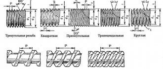
By profile type they are divided into:
- triangular;
- trapezoidal;
- round;
- rectangular;
- special.
Round threads are used in fire fittings and plumbing fittings.
Trapezoidal ones are used in running mechanisms to transmit translational motion. The most common are triangular threads, which we will discuss below.
Drilling for threads requires knowledge of its other characteristics. Based on the movement of rotation, the thread contours are divided into right and left.
For a right-hand thread, the profile groove is formed by rotation to the right side and longitudinal movement away from the entry point. For left-hand threads, rotation is directed in the opposite direction. In technology, right-hand threads are more common and in their coding this is implied by default and is not indicated additionally. LH marks appear in the left-hand thread markings. Depending on the number of starts, threads can be single-start or multi-start (usually no more than two- and three-start). Multi-start threads allow working under heavy loads.
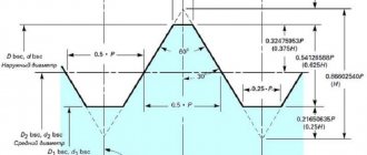
Important criteria influencing the choice of a drill for a thread are its nominal diameter, as well as the pitch. The diameter corresponds to the actual diameter of the outer profile.
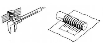
The thread pitch is the distance between the vertices of the nearest two vertices of the profile. The step can be large or main and small (there may be more than one). The thread length is the full size of the profile cutting area on the part.
To select a drill for threading, you also need to know that, based on the totality of thread parameters, threads are classified into several main types:
- Metric. The most commonly used thread in the engineering industry and in household items. Its main dimensions are fixed in GOST 24705-81. Designated by the letter M indicating the nominal diameter. For example, M6 defines a metric thread with a diameter of 6 millimeters, right rotation, coarse pitch.
- Inch threads are used in countries where the inch system of sizing is adopted. The size is indicated in inches – ½”.
- Cylindrical pipe threads have found application in plumbing for detachable connections of units, parts and fittings. Its dimensions are determined according to GOST 6357-81. The designation contains the letter G and the size in inches – G ¾, G 1.
- Inch tapered threads in accordance with GOST 6111-52 are used in low-pressure pipelines.
- Tapered metric threads are used in pipeline connections and are determined according to GOST 25229-82.
- Trapezoidal threads are used in moving mechanisms to transmit translational motion.
- Round thread is determined according to GOST 13536-68 and is used in sanitary fittings.
Tables for selecting the diameter of a drill for threading
When making an internal thread, a hole is pre-drilled for it. It is not equal to the diameter of the thread, since when cutting, part of the material is not removed in the form of chips, but is squeezed out, increasing the size of the protrusions. Therefore, before application, it is necessary to select the diameter of the drill bit for the thread. This can be done using tables. They are available for every type of thread, but here are the most popular ones - metric, inch, pipe.
| Metric thread | Inch thread | Pipe thread | |||||
| Thread diameter, inches | Thread pitch, mm | Drill diameter, mm | Thread diameter, inches | Thread pitch, mm | Drill diameter, mm | Thread diameter, inches | Threaded hole diameter, mm |
| M1 | 0.25 | 0,75 | 3/16 | 1.058 | 3.6 | 1/8 | 8,8 |
| M1.4 | 0,3 | 1,1 | 1/4 | 1.270 | 5.0 | 1/4 | 11,7 |
| M1.7 | 0,35 | 1,3 | 5/16 | 1.411 | 6.4 | 3/8 | 15,2 |
| M2 | 0,4 | 1,6 | 3/8 | 1.588 | 7.8 | 1/2 | 18,6 |
| M2.6 | 0,4 | 2,2 | 7/16 | 1.814 | 9.2 | 3/4 | 24,3 |
| M3 | 0,5 | 2,5 | 1/2 | 2,117 | 10,4 | 1 | 30,5 |
| M3.5 | 0,6 | 2,8 | 9/16 | 2,117 | 11,8 | — | — |
| M4 | 0,7 | 3,3 | 5/8 | 2,309 | 13,3 | 11/4 | 39,2 |
| M5 | 0,8 | 4,2 | 3/4 | 2,540 | 16,3 | 13/8 | 41,6 |
| M6 | 1,0 | 5,0 | 7/8 | 2,822 | 19,1 | 11/2 | 45,1 |
| M8 | 1,25 | 6,75 | 1 | 3,175 | 21,3 | — | — |
| M10 | 1,5 | 8,5 | 11/8 | 3,629 | 24,6 | — | — |
| M12 | 1,75 | 10,25 | 11/4 | 3,629 | 27,6 | — | — |
| M14 | 2,0 | 11,5 | 13/8 | 4,233 | 30,1 | — | — |
| M16 | 2,0 | 13,5 | — | — | — | — | — |
| M18 | 2,5 | 15,25 | 11/2 | 4,33 | 33,2 | — | — |
| M20 | 2,5 | 17,25 | 15/8 | 6,080 | 35,2 | — | — |
| M22 | 2,6 | 19 | 13/4 | 5,080 | 34,0 | — | — |
| M24 | 3,0 | 20,5 | 17/8 | 5,644 | 41,1 | — | — |
Once again, please note that the diameter of the drill bit for the thread is given for large (standard thread).
Thread cutting tools
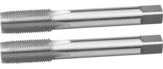
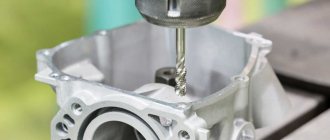
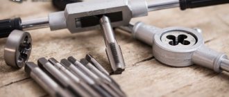
To form an internal thread in a part, a specialized tool is used - taps. They are cylindrical rods with a cut thread profile in a mirror image. But before using the tap, it is necessary to obtain a hole with the required diameter in the workpiece. We will explain below what the diameters of drills for threads should be, and in this section we will describe the thread-cutting tool.
In addition to the screw profile, the cylindrical surface of the tap has longitudinal grooves, which extend beyond the working part of the tool in size. These grooves are designed to remove metal shavings from the working area. In addition, these axial grooves divide the tap rod into several elements - combs. Their sharp edges are the main working elements of the tap. The tail part and square of the tool are designed for fixation in the spindle and chuck of the machine or in the driver. The working area of the tap is divided into cutting and calibrating parts. The cutting or tapping part cuts a groove in the hole, and the calibration part brings the dimensions of the thread profile into exact compliance with the required ones.
If one universal tap is used for cutting, then along its length it will have several areas with different characteristics of the working profile. This allows you to simultaneously cut out a layer of metal, remove burrs and irregularities, and also bring the dimensions to the required value. Taps, whose working profile has constant dimensions, are used to update the damaged profile of an existing internal thread. But more often in practice, several taps are used, which are used in turn.
The roughing tap cuts a groove of insignificant thickness on the inner cylindrical surface, that is, such a groove is a preparatory groove. Then, using a finishing tap, the groove is cut to the required depth, and also cleaned and leveled.
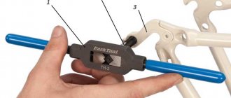
For large diameters and complex thread profiles, an adapter tap can also be used. When cutting threads manually, special holders called knobs are used. The shank of the thread-cutting tool is fixed in them. Also, the knob, due to the lever, allows you to reduce the force of manual action on the tool.
Thread hole parameters
The dimensions of the prepared hole must strictly correspond to the nominal thread sizes. It is also necessary to form a chamfer, which will facilitate the centering of the threading tool. The length of the hole must exceed the length of the thread, since an undercut consisting of a run-out and an undercut will form in its lower part. To determine the dimensions of these parts of the preparation hole, you should be guided by the data of GOST 10549-80 and GOST 27148-86.
When working with brittle materials such as cast iron, the drilling depth should be increased by an additional 25%. For many lightweight alloys, the increase factor is increased even more.
But the most important parameter of the hole is its diameter, so you need to choose certain sizes of drill bits for the thread. These dimensions will vary depending on the type of thread and its geometric characteristics. If the hole is larger than necessary, the resulting thread will have a groove that is too shallow. This will lead to a decrease in reliability and subsequent destruction of the threaded connection. If the diameter of the hole is too narrow, then it will be impossible to cut a thread in it efficiently. This is more likely to cause the threading tool to break.
It should be borne in mind that thread cutting can be performed in almost all common metals and alloys. The exception is brittle or hard metals, such as hot iron. It will not be possible to achieve a high-quality thread profile, and therefore you should not count on the reliability of this threaded connection.
Tables for selecting the diameter of a drill for threading
When making an internal thread, a hole is pre-drilled for it. It is not equal to the diameter of the thread, since when cutting, part of the material is not removed in the form of chips, but is squeezed out, increasing the size of the protrusions. Therefore, before application, it is necessary to select the diameter of the drill bit for the thread. This can be done using tables. They are available for every type of thread, but here are the most popular ones - metric, inch, pipe.
| Metric thread | Inch thread | Pipe thread | |||||
| Thread diameter, inches | Thread pitch, mm | Drill diameter, mm | Thread diameter, inches | Thread pitch, mm | Drill diameter, mm | Thread diameter, inches | Threaded hole diameter, mm |
| M1 | 0.25 | 0,75 | 3/16 | 1.058 | 3.6 | 1/8 | 8,8 |
| M1.4 | 0,3 | 1,1 | 1/4 | 1.270 | 5.0 | 1/4 | 11,7 |
| M1.7 | 0,35 | 1,3 | 5/16 | 1.411 | 6.4 | 3/8 | 15,2 |
| M2 | 0,4 | 1,6 | 3/8 | 1.588 | 7.8 | 1/2 | 18,6 |
| M2.6 | 0,4 | 2,2 | 7/16 | 1.814 | 9.2 | 3/4 | 24,3 |
| M3 | 0,5 | 2,5 | 1/2 | 2,117 | 10,4 | 1 | 30,5 |
| M3.5 | 0,6 | 2,8 | 9/16 | 2,117 | 11,8 | — | — |
| M4 | 0,7 | 3,3 | 5/8 | 2,309 | 13,3 | 11/4 | 39,2 |
| M5 | 0,8 | 4,2 | 3/4 | 2,540 | 16,3 | 13/8 | 41,6 |
| M6 | 1,0 | 5,0 | 7/8 | 2,822 | 19,1 | 11/2 | 45,1 |
| M8 | 1,25 | 6,75 | 1 | 3,175 | 21,3 | — | — |
| M10 | 1,5 | 8,5 | 11/8 | 3,629 | 24,6 | — | — |
| M12 | 1,75 | 10,25 | 11/4 | 3,629 | 27,6 | — | — |
| M14 | 2,0 | 11,5 | 13/8 | 4,233 | 30,1 | — | — |
| M16 | 2,0 | 13,5 | — | — | — | — | — |
| M18 | 2,5 | 15,25 | 11/2 | 4,33 | 33,2 | — | — |
| M20 | 2,5 | 17,25 | 15/8 | 6,080 | 35,2 | — | — |
| M22 | 2,6 | 19 | 13/4 | 5,080 | 34,0 | — | — |
| M24 | 3,0 | 20,5 | 17/8 | 5,644 | 41,1 | — | — |
Once again, please note that the diameter of the drill bit for the thread is given for large (standard thread).
Selecting the diameter of the drill for threading
The drill size must strictly correspond to the nominal thread diameter. The most reliable sizes of holes for metric threads are given in GOST 19257-73 . This standard provides hole sizes for any thread diameter, taking into account the thread pitch and the applicable tolerance range. When working, it is convenient to have on hand a table of drills for threads, in which data on holes for the most commonly used standard thread sizes should be collected.
The size of the drill for threading, when there is no table at the right time, can be determined by the following method. You need to subtract the pitch value from the thread diameter. A drill for M6 thread with a main pitch will have a diameter of 5 mm. This is calculated by subtracting the step value of 1.0 mm from the diameter of 6 mm: 6 mm – 1.0 mm = 5.0 mm. A drill bit for an M4 thread with a main pitch will have a diameter of 3.3 mm: 4 mm – 0.7 mm = 3.3 mm. In this way, the drill diameter can be determined for a thread of any nominal diameter. To check this calculation, it is better to look at the GOST table.
To determine from the table which hole to drill for the M10 thread, you need to look at the last line. With a coarse pitch of 1.5 mm, we need to drill a hole with a diameter of 8.5 mm. To determine which hole to drill for the M8 thread, look at the last column of the corresponding row and see a diameter of 6.7 mm. More detailed tables are presented in GOST 19257-73 .
The question often arises as to which thread drill bits should be used. It all depends on the brand of material being processed.
For regular low-alloy steel, standard twist drills made from high-speed steel are used. To work with stainless and high-alloy steel, it is recommended to use a thread drill made from steel alloyed with cobalt and tungsten.
Hole parameters
The following thread parameters are distinguished:
- diameters (internal, external, etc.);
- profile shape, height and angle;
- step and entry;
- others.
The condition for connecting parts to each other is the complete coincidence of the external and internal threads. If any of them are not performed in accordance with the requirements, the fastening will be unreliable.
The fastening can be bolted or stud, which, in addition to the main parts, includes nuts and washers. Before joining, holes are formed in the parts to be fastened, and then cutting is carried out.
To perform it with maximum accuracy, you should first form a hole by drilling, equal to the size of the internal diameter, that is, formed by the tops of the protrusions.
When performing a through design, the diameter of the hole must be 5-10% larger than the size of the bolt or stud, then the following condition is met:
- dresponse = (1.05..1.10)×d,
where d is the nominal diameter of the bolt or stud, mm.
To determine the hole size of the second part, the calculation is carried out as follows: the pitch value (P) is subtracted from the value of the nominal diameter (d) - the resulting result is the desired value:
- dresponse = d - P,.
The calculation results are clearly demonstrated by the table of threaded hole diameters, compiled according to GOST 19257-73, for sizes 1-1.8 mm with small and main pitches.
| Nominal diameter, mm | Pitch, mm | Hole size, mm |
| 1 | 0,2 | 0,8 |
| 1 | 0,25 | 0,75 |
| 1,1 | 0,2 | 0,9 |
| 1,1 | 0,25 | 0,85 |
| 1,2 | 0,2 | 1 |
| 1,2 | 0,25 | 0,95 |
| 1,4 | 0,2 | 1,2 |
| 1,4 | 0,3 | 1,1 |
| 1,6 | 0,2 | 1,4 |
| 1,6 | 0,35 | 1,25 |
| 1,8 | 0,2 | 1,6 |
| 1,8 | 0,35 | 1,45 |
An important parameter is the drilling depth, which is calculated from the sum of the following indicators:
- screw-in depth;
- reserve of external thread of the screwed-in part;
- her undercut;
- chamfers.
In this case, the last 3 parameters are for reference, and the first is calculated through the coefficients for taking into account the material of the product, which are equal for products from:
- steel, brass, bronze, titanium – 1;
- gray and ductile cast iron – 1.25;
- light alloys – 2.
Thus, the screw-in depth is the product of the material factor and the nominal diameter, and is expressed in millimeters.
Types of carving
According to the measurement system, threads are divided into metric, expressed in millimeters, and inch, measured in corresponding units. Both of these types can be made in either cylindrical or conical shapes.
They can have profiles of various shapes: triangular, trapezoidal, round; divided according to application: for fasteners, plumbing elements, pipes and others.
The diameters of the preparation holes for threading depend on its type: metric, inch or pipe - this is standardized by the relevant documents.
Holes in pipe connections, expressed in inches, are specified in GOST 21348-75 for cylindrical shapes and GOST 21350-75 for conical shapes. The data is valid when using copper and nickel-free steel alloys. The cutting is carried out inside the auxiliary parts into which the pipes will be screwed - slates, clamps and others.
GOST 19257-73 shows the diameters of holes for cutting metric threads, where the tables show the size ranges of nominal diameters and pitches, as well as the parameters of holes for metric threads, taking into account the values of maximum deviations.
The data given in the GOST 19257-73 table confirms the calculation given above, in which the parameters of holes for metric types are calculated from the nominal diameter and pitch.
How is thread cutting done?
When it is determined which thread drill is needed and the hole is cut, you can move on to the next stage - direct cutting.
The walls of the hole should be cleaned of foreign contaminants. This can be done with a metal brush or by blowing it with air. The workpiece must be securely fixed. The tap must be installed in the hole strictly parallel to its axis. For high-quality centering in the hole when drilling, a chamfer is usually made at 30 or 45 degrees. The parallelism of the axes of the tap and the hole is checked using a square, which is applied to the surface of the tool and the edge of the part. Then the thread is cut by rotating the tool clockwise (in the case of a right-hand thread). It is especially important to cut the first turns of the thread exactly.
The crank is turned gradually. Having made a full turn, the tap is unscrewed half a turn. If the applied force increases, the tap is removed from the hole and chips are removed from it. It is recommended to use lubricant during operation. This can be a special lubricant, for example, a paste based on fats and wax, which is applied directly to the instrument. A replacement can be drying oil, kerosene or machine oil. Thread cutting on a drilling machine is carried out using special taps. The cutting process itself is no different from handmade technology.
