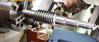
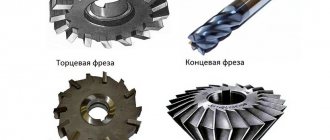
Modification 5M14
The 5M14 universal mechanical gear shaping machine, like its analogues, is intended for cutting teeth of various types of cylindrical wheels.
The chisel tip of the equipment has a small overtravel, which makes it possible to cut gears in blocks. The work process is carried out by rolling the part with circular modular devices. The unit has a vertical layout, the chiselling tool is made in the form of a gear wheel, the module of which is identical to that of the workpiece being processed. During operation, the cutter receives translational and reciprocal movement and synchronous rotation around its own axis. At the beginning of the operation, the working part moves relative to the axis of the workpiece after each stroke in automatic mode. This process continues until the required tooth height is reached.
Processing and stopping of the equipment is carried out under the control of an automatic controller.
Varieties
Gear shaping machines are divided into three main types:
- Modifications with a table movable in a horizontal plane, allowing for infeeding. Its design also includes a fixed stand.
- Options with a fixed table and a stand that moves horizontally and serves to transport the tool at the time of cutting.
- Models with a static table, a horizontally moving stand and a carriage capable of extending the slotting tip vertically, changing the position of its stroke.
An automated unit with a fixed table has more advantages than its counterparts. To make it possible to produce conical teeth, one of the tool axes is mounted at a certain angle. On machines used in mass production, there is an intermediate plate placed under the vertical stand. Universal modifications are equipped with the ability to tilt the table or stand within a range of 10 degrees.
Read also: Fuel pump for transferring diesel fuel
Chain for cutting the cutter into the workpiece (radial feed).
Radial cutting of a cutter into a workpiece in machines mod. 514, 512, 5A12, 5B12, 5M14 and others are carried out using a cam, which can be one-, two- or three-pass. According to the selected cam, the workpiece is cut in one, two or three passes (depending on the material, module and required accuracy). The cam has two sections: cutting in (a, B) and running in (bc).
In the cutting area, the radius of the cam gradually increases by the amount H - the pitch of the spiral rise. When processing in one pass, after turning the cam by 90° and turning each of them (after cutting in), the table with the workpiece made one revolution. Calculated movement in a radial feed chain
Radial feed kinematic chain: shaft II, chain drive shaft IV, XIII, radial feed guitar shaft XIV, wheels EMBED Equation.3 shaft XV, worm gear EMBED Equation.3 coupling M2, shaft XVI, transmission EMBED Equation.3 shaft XVII, cam K1 radial plunge.
Kinematic balance equation:
Types of machine drives
The design of gear hobbing devices is characterized by high technological complexity. Manufacturers offer various drive designs with the following features:
- Worm type table drive. A special feature of the design is the installation of an additional worm with a variable coil thickness, the gap of which is adjustable over a wide range.
- Separate worm gear installed in a separate unit. Adjustment is carried out using radial movement.
- A scheme in which two worm gears with opposite directions of turns are installed on the spindles is considered universal. By adjusting one gear, the current gap is changed.
- Hydraulic type. In this case, the transmission is driven by hydraulic fluid supplied by a pump.
- Double type. The adjusting gear is made of two halves. When their position relative to each other changes, the gap changes.
- Conical. When implementing this scheme, gears with a small taper are used. With axial displacement, the engagement changes and the gap is corrected.
- Multi-toothed. Using a spindle-mounted multi-tooth gear allows the speed of the base wheel to be slowed down. The kinematic chain is adjusted by braking the wheel.
When considering various drives, it is worth mentioning the use of CNC gear hobbing machines.
The use of numerical control narrows the range of responsibilities of the operator due to the absence of a division guitar. Note that the cost of such machines is quite high, which does not allow their use in enterprises with small production volumes.
Features of CNC models?
Today, the most widespread models are those operating from a numerical control unit. The characteristics of such equipment are determined by the following points:
- The machine can operate in automatic mode. To do this, you need to install the workpiece and set the required program.
- The operating instructions determine the possibility of obtaining high-precision parts. All nodes are positioned with high accuracy relative to each other and the dimensional error is significantly reduced.
- There are models that automatically load/unload workpieces. They are installed in conveyor production shops when a part is transferred from one processing stage to another.
CNC gear shaping machine
CNC gear shaping machine model
There are a large number of design options for CNC gear shaping machines. When considering a passport, you need to pay attention to what language or programming method is used. The electrical circuit of CNC models is more complex than conventional ones.
Kinematic diagram and setup of gear shaping machine 5A12
Kinematic diagram of gear shaping machine 5a12
The kinematic diagram of the machine provides the following basic movements:
Reciprocating movement of the cutter
From an electric motor with a power of N = 1.2 kW at n = 960 rpm, through a pair of bevel wheels 1 and 2, replaceable speed wheels A and B, shaft I rotates. At the front end of shaft I there is a crank gear disk 33, which rotates the connecting rod 35 transmits the rocking motion to the rocker arm 36. The toothed sector 37, mounted on the rocker arm, is in engagement with a circular rack on the slider (spindle) 38 and imparts reciprocating motion to it.
Rotation of the cutter
On shaft I there is a four-threaded worm 3, which meshes with a worm wheel 4. When shaft I rotates through a worm pair 3-4 and replaceable circular feed wheels B and D, the movement is transmitted to shaft II. Next, shaft III rotates through conical wheels 5 and 6 (a reversible mechanism that changes the direction of rotation of the cutter). The conical wheel 7, mounted on shaft III, engages with wheel 8, freely sitting on shaft IV. When clutch M1 is engaged, rotation is transmitted to shaft IV through a worm pair 9 10 to the slider. Guide half-bushings of the same type as on machine 514 are fixed on the slider and in the hole of the worm wheel (Fig. 94).
Table rotation
At the right end of shaft II, a replaceable gear wheel D of the division guitar is fixed, which through replaceable wheels E, G and 3 imparts rotation to shaft V. Further, through bevel wheels 11-12 shaft VI receives rotation and through bevel wheels 13-14 (reversible mechanism) - worm 15 and worm wheel 16, rotating the table with the workpiece.
Radial feed (plunge)
Just like in the 514 machine, the plunging is controlled by a cam, but in this machine the cam rotates continuously and evenly both during the plunging and after the plunging stops. One of the three wheels of the gear block, sitting on a sliding key on shaft V, is engaged with the corresponding wheel mounted on shaft VI. Thus, through wheels 17-18 or 19-20, or 21-22 and then through the worm pair 23-24, the plunge cam K1 is rotated. Wheel 24 (Fig. 114) sits freely on the feed cam shaft and rotates this shaft with the help of a pawl a, which engages with a ratchet wheel b mounted on the shaft. The rotation of cam K1 causes longitudinal movement of the rack 28, which in turn pushes the caliper with the cutter in the direction of the product, thereby imparting a radial feed (plunging). A weight 42, suspended from a chain stretched over a sprocket 43, tends to turn the sprocket, and with it the rack and pinion wheel 30 counterclockwise. Since the rack wheel 30 is in engagement with the rack 31 attached to the caliper, the caliper always tends to move along the machine guides to the left. Due to this, roller H, fixed at the end of the rack 28, is constantly pressed against the curved surface of the plunge cam K1.
Caliper installation movement
The installation movement of the caliper is achieved by manually rotating (handle P5) the worm 25, on the axis of which a dial (circular scale) is mounted. In this case, the worm wheel 26 and the wheel 27 attached to it on the same shaft rotate, engaging with the rack 28. The rack remains motionless, since under the action of the load its roller is pressed against the plunge cam, and the caliper moves along the guides relative to the rack. When the worm 25 is stationary, the caliper relative to the rack cannot move, since the worm wheel 26 is braked by the worm. It is known that worms with a small lift angle are called self-braking and, no matter what the load on the wheel, do not turn on their own. To quickly move the caliper manually, use the square Po on the wheel axis 29. In this case, you need to remove the worm 25, which prevents rotation, from engagement with the wheel 26.
Reciprocating movement of the table, retracting the workpiece when the cutter is idling
This movement is obtained from cam K2, mounted on shaft I. The cam, with the help of a pusher 39 and a crank lever 40, pushes the rod 41, which moves the table with the workpiece along the guides. The stroke is no more than 0.5 mm.
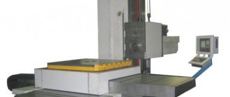
7D430, 7D450 Slotting machine with hydraulic drive. Purpose and scope
The hydroficated slotting machine model 7D430 and 7D450 is designed for the production of keyways, splines and grooves on shaped and flat surfaces, for slotting flat and shaped surfaces, cutouts, grooves in cylindrical and conical holes and slotting with an undercut of up to 10°.
The machine is designed for processing by chiselling flat and shaped external surfaces of product surfaces with a height of up to 500 mm and processing of internal surfaces of products with a height of up to 250 mm. The machine is suitable for use in individual and small-scale production, as well as in repair shops.
The machine is designed for processing grooves and grooves in a variety of parts, as well as various types of dies installed directly on the table or in fixtures. The ability to rotate the frame with the cutter allows you to process inclined planes without changing the position of the part.
Description of the design of the machine and the operating principle of the machine 7D430, 7D450
The presence of three types of table feeds (longitudinal, transverse and circular) makes it possible to process several surfaces on this machine from one installation. The presence of mechanical table feeds, an automatic stop mechanism, and remote control allows multi-machine service.
The table moves both manually and mechanically. The circular feed of the table makes it possible to process round parts and gears on the machine.
Technical characteristics of the slotting machine with hydraulic drive 7D430 (7D450)
Manufacturer Gomel Machine Tool Plant, StankoGomel.
Basic parameters of the machine in accordance with GOST 1141-74.
- Table diameter – Ø 630 (Ø 800) mm
- Stroke of the cutter – 120..320 (120..500), mm
- Distance from the table plane to the cutter guides, mm – 500 (700) mm
- Distance from the table plane to the bottom edge of the cutter head – 500 (710) mm
- Distance from the cutter to the frame (reach) – 615 (710) mm
- The largest longitudinal table movements are 650 (800) mm
- The largest transverse table movements are 510 (650) mm
- The largest movements of the table are circular – 360°
- The largest dimensions of the cutter holder are 32 x 20 (40 x 25) mm
- Electric motor power – 11 kW
- Total weight of the machine – 5.7 (8.2) t
The drive for moving the cutter and the drive for feeding the table for each double stroke of the cutter are hydraulic.
The machine has step-throttle speed control.
The speed of the cutter is controlled by two handles located on the control panel cover. One of them sets four stages, the other smoothly regulates the speed within each stage.
Changing the direction of movement of the cutter occurs by switching the control spool with two stops located on the control panel cover. The same stops regulate the length and relative position of the cutter stroke. The speed of movement of the cutter is constant over the entire stroke length.
The cutter slide is hinged in the cheeks of the upper frame and can be rotated together with the cutter in a vertical plane up to 10° in the longitudinal direction of the frame.
The machine table has three types of feeds:
- longitudinal
- transverse
- circular
Rapid movement of the table in the indicated directions is carried out by a separate electric motor.
The table can also be moved manually in three directions.
The feed box has a dividing mechanism for rotating the table, which allows you to accurately divide the workpiece into the required number of parts.
The machine has a mechanism that allows you to configure the machine for a certain length of processing of a part and automatically turns off the machine at the end of processing; in this case, the cutter stops in the upper position. The design of the machine ensures automatic removal of the cutter from the product during the reverse stroke of the cutter.
The pendant push-button station provides remote control - starting and stopping the main movement electric motor, rapid movement electric motor, electric cooling pump, as well as starting and stopping the cutter and setting it to adjustment mode.
The lubrication of the cutter guides and the return of oil to the bath are carried out by a double plunger pump. The pump drive is eccentric. In addition, there is a manual pump to lubricate the guides. Lubrication of table guides is centralized from manually driven lubricators.
Gear planing machines
Gear planing machine mod. 5A250 operates using the rolling method and is designed for rough and finishing cutting of spur and bevel gears in serial and mass production. Using a special attachment head, you can also cut screw teeth.
Technical characteristics of the machine mod. 5A250
| Largest diameter of cut gears, mm | 500 |
| Number of teeth of cut wheels | 10…100 |
| Number of double strokes of sliders-cutters | 73…470 |
| Duration of cutting one tooth, s | 8…123 |
Straight tooth cutters of accuracy classes A, B:
- disk in the range of modules (M 1...8 mm), cup (M 1...6.5 mm) and tail (M 1...5 mm) according to GOST 9323-79 and GOST 6762-79 and special;
- fine-module disk and tail ones in the range of modules M 0.3...0.9 mm according to GOST 10059 and special;
- cutters for files.
Disc shaver:
standard and special in the range of modules 0.3...8 mm (85...3 DP) with pitch diameters 85, 180, 250 and 280 mm accuracy classes A, B according to technical specifications GOST 10222-81, GOST 8570-80 for processing cylindrical gears wheels with an involute profile of 5-8 degrees of accuracy.
Reference measuring wheels:
standard and special according to GOST 6512-74 and customer drawings in the range of modules 0.3...8 mm, 4...5 degrees of accuracy.
CJSC "Heavy Gear Cutting Machines" is the only enterprise in Russia and the CIS countries that produces a complete set of equipment (gear cutting, gear broaching, gear grinding, gear lapping, control rolling, hardening machines) for the production of bevel and hypoid gears with a circular tooth and bevel spur gears using methods milling, planing and broaching. The plant produces more than 30 modern models. The machines are deeply modernized technological equipment based on models that have proven themselves well before. The most popular models (527VF3, 5S280VF3, 5A26VF3, 5A270VF3, 5A872VF3, 5A284FZ, etc.) are supplied with Siemens CNC systems (Fig. 4).
Currently, the plant produces unique machines 5A284 and 5E283 for the production of gears with a diameter of 1600 mm and a module of 30 mm (Fig. 5, 6).
The plant has mastered a new direction - the production of CNC machines for the production of cylindrical gears with a diameter of up to 2000 mm, module 25 mm. Currently, gear shaping machines 5S140F3, 5S150F3 (Fig. 7), 5S161F3 and gear hobbing machines models 53S42F4, 53S11F4, 53S80F4, 53S50F4 with Siemens CNC are supplied.
The delivery of each unit of gear-processing equipment is accompanied by the transfer of technology for processing parts. Based on the technical requirements of customers, optimal supply options for the following gear-processing complexes are developed and proposed:
- specialized with technology for mass production of standard gears;
- universal with technology for the production of gears of various types.
Rice. 4. General view of the machine model 527VF3
Rice. 5. General view of the machine model 5A284
Rice. 6. General view of the machine model 5АЭ283
Rice. 7. General view of the machine model 5С150Ф3
Gear-processing complexes include universal 6-axis coordinate measuring machines for testing gears and gear-cutting tools, the main advantages of which are:
- 6 degrees of freedom of movement of the probe;
- built-in self-calibration system;
- two-stage vibration protection system.
Guidelines
for full-time, evening and part-time students
Tula 2006
Developed by G.V. Sundukov, associate professor
The developer expresses gratitude
for constructive comments on the content
engineer N.I.’s job desire Lapkina
| Considered at a meeting of the ACC department. Protocol No. 4 of January 10, 2006 Head Department ___________________ A.N. Inozemtsev |
1GOAL OF THE WORK
The purpose of the work is to consolidate the educational material on gear shaping machines: studying the structure and operation of gear shaping machines, analyzing the kinematics of a semi-automatic gear shaping machine mod. 5A12, calculation of machine settings for processing a cylindrical gear, familiarization with setting up and setting up a machine for processing parts.
2 sequence of
WORK
1) Study of the operating principle and capabilities of gear shaping machines.
2) Study of the design, operation and kinematics of a semi-automatic gear shaping machine mod. 5A12; recording equations for kinematic balance of drives and deriving tuning formulas.
3) Performing individual tasks to calculate the settings of the machine mod. 5A12 for the production of straight teeth of cylindrical wheels and drawing up a report on the work.
4) Familiarization with setting up the machine and processing a gear on it.
ATTENTION: being near the machine and operating with it is allowed only in the presence of a teacher or laboratory assistant!
3 General information about gear shaping machines
and cutting gears using the rolling method
On gear shaping machines, cylindrical wheels of external and internal gearing with straight and helical teeth, blocks of gear wheels, wheels with collars, gear sectors, spline rollers, gear racks, ratchets, etc. are cut. (Fig. 1). These machines are indispensable for cutting blocks of gears, as well as gears with internal gearing.
| Based on the location of the spindle, gear shaping machines are divided into vertical and horizontal. Vertical gear shaping machines are most widely used in industry. | Rice. 1. Products manufactured on gear shaping machines |
Gear cutting on most models of gear shaping machines is carried out by the rolling method, on some models - by the copying method.
On machines operating according to the rolling-in method
, in the process of gear shaping, the meshing of two cylindrical gears is reproduced (Fig. 2). One of these wheels has teeth equipped with cutting edges and is a cutting tool - a gear cutter, and the other, which does not have teeth, is a blank for the wheel to be cut. The cutter and the workpiece must be rotated in the same way as two gears would rotate if they were in mesh. To do this, the workpiece and the cutter are connected by a rigid kinematic chain with replaceable wheels for adjustment to obtain a product with the required number of teeth.
When chiseling the teeth of wheels with external gearing, the direction of rotation of the cutter is opposite to the direction of rotation of the workpiece, and when chiselling wheels with internal gearing, the direction of their rotation coincides. Therefore, a reversing device is included in the kinematic chain connecting the movement of the cutter and the workpiece.
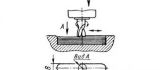
To carry out cutting, the cutter is given a reciprocating movement along the axis of the part. The cutting process occurs only during the working stroke of the cutter - the downward stroke. During the reverse idle motion of the cutter, the rotation of both it and the workpiece continues. Therefore, the layers of metal to be cut will roll onto the teeth of the cutter. At low feeds, this can cause jamming of the cutter and the workpiece and the emergence of a large friction force acting on the rear edges of the tool teeth and leading to their intensive wear, and
| at high feeds – jamming and breakage of the cutter teeth. To avoid this, when the cutter moves upward, the workpiece moves away from it. By the beginning of cutting, when the cutter moves downwards, the workpiece returns to its working position. To start the gear shaping process and obtain teeth with the required height h, the shaper must gradually | Rice. 2. Scheme of movements during chiselling straight teeth cylindrical wheel external gear |
foam into the workpiece.
Principle of operation
The technical characteristics of gear shaping machines allow the cutting process to be carried out through the reciprocating movement of the working part. Semi-automatic units have a vertical layout. Setting the center distance and cutting the tooth to the required depth is adjusted using a table moved by a hydraulic cylinder. The equipment is capable of operating in setup and semi-automatic mode with the possibility of reusable finishing of products.
An electric DC motor allows you to change the circular feed. It receives power from a special amplifier with an automatic switch that switches the cyclic processing of the workpiece. With the help of a three-speed main drive motor, double tool movements per minute can be transformed. Radial insertion is carried out by the operation of a wedge slider moved by a hydraulic cylinder. The general tapping range is carried out through the stops, and the idle retraction is carried out through the spindle. Removal of the part at an angle is realized by shifting the stand relative to the axial part of the table. The revolutions of the workpiece are taken into account by an electronic pulse controller, which makes it possible to adjust the rolling arc. The machining of internal gears involves automatic upward movement of the tool.
Model 5122
Gear shaping machines 5122 are also designed for cutting cylindrical geared circles by rolling in a slotting tool. The units are used in mass and individual production.
Equipment parameters:
- The maximum dividing size of the workpiece being processed is 200 mm.
- Gear module – 5.
- The maximum width of the processed crown is 50 mm.
- The working surface of the table in diameter is 250 mm.
- The nominal value of the cutter is 100 mm.
- Weight – 4.4 tons.
- Overall dimensions – 2/1.45/1.96 m.
- The power of the power plant is 3 liters. With.
- The number of double strokes of the working part in one minute is 200/280/305/400/430/560/615/850.
Scope of application and operating principle
Using gear shaping machines, you can cut a chevron or worm wheel of a spur or helical type. The functionality of the units is expanded when they are equipped with a special device - a disk or finger type cutter, which allows you to cut any type of wheels with internal gearing. At the same time, the disk cutter is multifunctional; by installing it, you can not only process the teeth, but also cut through the internal plane of the part.
Modern gear shaping machines make it possible to accurately form teeth on wheels of a minimum size (up to 12 mm inclusive), while up to 30 modules can be applied using a hob cutter, up to 40 with a disk cutter, and up to 75 with a finger shaper. If the unit is equipped with a reverse motion system, then teeth can be cut even on wheels with a closed chevron angle.
The main working tool of a gear shaping machine is a cutter - a rigidly fixed gear wheel, one side of which is attached to the supporting frame of the machine, and the second is in contact with the workpiece being processed and, using a cutting edge made of a high-hard alloy, forms teeth on it.
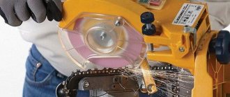
Teeth cutting principle
The teeth on the workpieces are cut using rolling technology, and the profile of the protrusions on the cutter may not correspond to the required profile configuration of the part. This makes it possible to cut workpieces with a different number of teeth using the same cutter.
Before starting work, the gear cutting machine is always run-in. The essence of running-in is to select the correct ratio of the teeth of the working tool in relation to the profile of the workpiece. During the running-in process, the part and the cutter each rotate around their own axes, while when cutting the outer wheels, the rotation is multilateral, while the internal wheels are unilateral.
Machining of inner and outer rings
When cutting, the cutter is given not only a rotational, but also a translational movement, due to which the profiled edge of the cutter cuts (chisels) teeth on the edge of the workpiece in contact with it. At the very beginning of cutting, it is impossible to set the gouge to the required depth due to the high resistance of the metal, so the working tool cuts into the workpiece sequentially due to radial feed, thereby increasing the depth of the teeth.
Upon completion of the full cycle of the working stroke, so that the teeth of the cutter and the edge of the part do not rub against each other while turning the wheel to its original position, the work table fixing the workpiece is moved back. There are also units in which the workpiece remains stationary, and the cutter itself moves. to menu
to menu
Design Features
Almost all modern gear shaping machines have a vertical layout. The main structural components of the unit are:
Diagram of a gear shaping machine
- Bed.
- Guitar break-in.
- The spindle in which the cutter is fixed.
- A work table in which the workpiece is mounted.
- Shtossel.
- Caliper guide.
- Guitar (circular feed).
- Lever for setting the cutting depth.
- Slotting support.
- Guitar (radial feed).
- Insertion mechanism.
- Cam drive mechanism.
- Plunge cam.
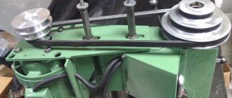
Let's consider the kinematic diagram of equipment of this type using the example of a 5M14 machine. It consists of four main chains - main movement, radial feed, rolling and circular feed. An electric drive is responsible for the main feed, the rotational torque from which is transmitted to the spindle through a V-belt transmission and a gearbox.
Kinematic diagram
data-ad-client=»ca-pub-8514915293567855″ data-ad-slot=»5929285318″>
The 5M14 gear shaping machine is equipped with a gear gearbox, allowing 4 speeds of the working tool. Speed adjustment is performed by changing the position of the gearbox gears. In addition to the main engine, the machine has 3 auxiliary drives, the first of which is responsible for the rapid rotation of the work table, and the rest drive the hydraulic drive and the cooling system pump. Overload protection of drives is provided by built-in thermal relays of class PTI-PT4. to menu
Purpose
Gear shaping machines, unlike other types of metalworking equipment, have a narrow direction. With their help you can:
- Carry out processing of worm or chevron wheels. It is acceptable to work with oblique and straight teeth.
- Cut teeth of different shapes on wheel parts up to 12 mm.
Modern equipment is complemented by some functions that expand their functionality. After installing the disk cutter, it becomes possible to process various surfaces, teeth of complex shapes, and different sizes.
Mechanism for implementing the automatic cycle of gear shaping machine 514
Diagram of the automatic cycle mechanism of gear shaping machine 514
Purpose of the automatic cycle mechanism
The purpose of this mechanism is that it controls the mechanism for cutting the cutter teeth into the body of the wheel being cut to a set cutting depth. When the required plunge depth is reached, the radial feed is automatically turned off and the counting device is turned on, controlling the number of full spindle revolutions. In addition, after a set number of table revolutions, the mechanism automatically moves the cutter away from the workpiece and turns off the machine.
In the process of cutting teeth, cam K1 moves roller P to the right (Fig. 107), the screw XVIII and caliper connected to it and installs the cutter sequentially in the positions appropriate for cutting. Cam K1 rotates from two mechanisms: a radial feed mechanism and a counting mechanism.
The operation of the radial feed mechanism was described above. The mechanism is turned on by turning lever P2 to the right and the lever is secured with lock F. While turning lever P2, its fork through rod T will engage clutch M2 (engaging worm wheel 40 with shaft XVI). At the same time, the rod T will shift the stop Y, which will lift the pawl C, disengaging it from the ratchet wheel X.
The left end of the lever P1, under the action of the spring P1, will rest on the protrusion of the cam K1, located on its rear side. During its rotation, cam K1 moves roller P and the screw XVIII connected to it to the right, and thus the cutter cuts into the workpiece. Before cutting begins, the cutter is brought manually by handle 4 (see Fig. 105) into contact with the surface of the workpiece. At the moment of completion of the plunge, the left end of the locking lever P1 (see Fig. 106) slides off the protrusion located on the back side of the cam K1, and the spring P1 lifts its right end with the lock and the lever P1 is released. The latter, under the action of the spring P2, turns to the left and with the rod T turns off the clutch M2, retracts the stop Y, freeing the pawl C, which, under the influence of its own weight, lowers and engages with the ratchet X. Cam K1 is now driven by shaft XI, on which the worm sits , rotating table XII with a workpiece.
On the same shaft (see Fig. 106) there is an eccentrically mounted cam K2, which imparts a rocking motion through the rod XIX to sector e (Fig. 107) with a pawl C attached to it. In this case, for each double stroke, the pawl captures one tooth of the ratchet wheel X. At this time, roller P will roll along the cylindrical part of cam K1 and therefore there will be no radial feed.
From the moment the cutter finishes cutting into the full height of the tooth, the process of processing the wheel blank begins, which continues for one revolution of the table with the workpiece. When the processing cycle ends, roller P enters the cavity of cam K1. Screw XVIII, together with the caliper, will move to the left under the action of the spring, disengaging the cutter from engagement with the cut wheel. At the same time, the stop B presses the limit switch KB and stops the machine.
The fast installation rotation of the table is transmitted from a separate electric motor MP (N = 0.5 kW, n = 1440 rpm) through a belt drive 80-180 to shaft XI and a dividing worm gear 1-240 of the table (see Fig. 106).