When drawing up a project for an external drainage network, it must include a sheet “table of sewer wells”. It displays all the wells, grouped into groups. They are listed indicating the operating parameters, in increasing order of the diameter of the pipes or trays.
For each unit, the main operating parameters, dimensions, depth of immersion in the ground, volume of the working part, and the amount of material spent on manufacturing are displayed. As a result, a complete list of containers accepted for a given system appears and are grouped by purpose and type.
Types and varieties
Scheme of a drop well with a water trench wall
At the moment, builders distinguish between several types of sewer pits:
- Inspection sewer wells. They are built if there is a need to control the functioning of the entire system.
- Drop wells. They are built on slopes, in beams and other places where differences in sewerage pipelines are possible.
- Turning. They are often installed as intermediate ones in areas where pipes are turned to prevent blockages
- Filtration. They have the function of waste water purification.
- Cumulative. Collect (accumulate) waste water.
However, in practice, the same pit can perform several functions at once.
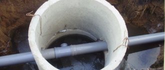
Sewer inspection wells provide access to sewer lines, which allows them to be inspected and repaired (if necessary) and makes it possible to control the degree of contamination, the presence of blockages and clean the system. Such pits are used in places where the direction of pipes changes, in the presence of slopes, when the diameter of the pipeline changes, in places where several pipes are joined/attached.
Well design
To assemble the tanks, concrete rings of a certain diameter are used. The dimensions of typical sewer wells are determined by the size of the equipment and the tasks for which the tank is being built. The general design of all structures is the same, a noticeable difference is found only in storm water tanks.
Working sewer tanks made of concrete consist of several elements:
- working part;
- shaft (aka neck;
- bottom;
- Luke.
The lower part is made up of a bottom and service rings. Their number determines the depth of immersion in the ground. Usually it exceeds the freezing level in winter, although such values are not needed for stormwater networks. The diameter of a sewer well is determined by the size and number of lines that enter and exit it. In addition, the type of well and its purpose are of great importance. Types of tanks:
- observation;
- turning;
- distribution;
- differential;
- extinguishing;
- cumulative;
- filtration.
Despite their different purposes, these units have almost the same design. The difference lies in the number of pipes and the presence of additional equipment - extinguishing shields, filtration grids and other equipment.
The neck of a sewer well is the area between the manhole casing and the top cover of the working part. It takes on external loads from layers of soil, weight from passing cars, and withstands the pressure of soil water. It is noteworthy that in areas of private houses, the neck and casing ring are often combined into one unit. This is allowed, since large loads on this element are not expected.
Materials
Concrete well dimensions
At the end of the 19th and beginning of the 20th centuries. all wells were made of brick. In the mid-20th century, reinforced concrete began to be made, but now plastic structures are most often used. They can significantly reduce the cost of construction work and installation costs. However, in the countries of the former USSR this type has not found its application, since it is not resistant to low temperatures. Now a number of Russian manufacturers have begun the development and production of plastic wells for the cold zone.
Externally, the designs made from all types of material are absolutely identical. They have a shaft pipe, a cover, and sewerage entry points. In this case, holes for sewer pipelines are laid out in a brick well, in reinforced concrete ones they are drilled, and in plastic ones they are usually made in advance. Therefore, the construction of reinforced concrete and brick ones is much more expensive compared to plastic ones.
The covers of all wells are standardly equipped with storm water inlets, which allows storm drainage to be introduced into them. Hatches are usually made of cast iron and have their own load classes. The most common classes are “B” and “D”, which can withstand 12.5 and 40 tons, respectively.
You need to build a sewer system and a well using your own funds, because this determines what type of material will be used.
Regulations
The table of sewer wells is compiled on the basis of current standards and rules (SNiP, SP). These are basic documents that list all the requirements for the design of containers, their sizes and other parameters. Any inconsistencies discovered during the defense are regarded as grounds for project rejection.
However, if you use only basic regulatory documents, the risk of making mistakes increases. For each tank you will have to select parameters separately, which will significantly slow down the preparation of the project. The structure of SNiP or SP is designed to list rules, requirements and standards. It is inconvenient for carrying out design work, so a special database has been created to help compilers - the Standard Project (TP). Currently, a more modern edition is used - TPR (Typical Design Solutions), which is a revised version of the database.
Sewer wells, Standard Project is a set of tables for different groups of containers. They are united by purpose, size, and features. The designer’s job is to select the desired option based on the values given in the columns.
Volume
The volume of the sewer well is greatly limited. Thus, the maximum permissible height is only 2500 mm. The diameter is a maximum of 1 meter, but modern ready-made wells have a diameter in the range of 400-700 mm.
For the calculation, the figure taken is 150 liters of drainage per person per day. For a family of 4 people, the consumption is assumed to be 700 liters per day. Based on this, the well must have a volume of at least 2.4 m3.
More accurately, the volume of the well is selected based on the type of soil in which it is planned to be installed. To increase the volume of the well (if necessary), you should build 1 or more additional wells nearby, connecting everything with overflow systems.
Main types of drop wells
Depending on the design of the drop well, the following varieties are distinguished:
- Changes in which there is a drain of water of a practical profile. There is a water well in the downstream;
- Tubular drops. Such wells have different designs, but they are all united by a single element - a vertical pipe;
- Drops that have a spillway wall;
- Chess multi-stage changes. They have different designs. In design feature - each stage extinguishes the energy of the flow;
- Rapid flow wells. They have small channels with a large slope.
Preparation for installation
Layout of the sewer well on the site
Before installing wells, sewer pipes should be laid. To do this, a detailed sewerage diagram is drawn, which is compiled based on existing regulatory documents. The diagram should take into account the following points:
- It is necessary to clearly determine the location of the sewer pipe exit from the basement/basement of the building. This affects the location of the object. At the same time, we must not forget that suction pumps must approach the well to pump out waste.
- The requirements of SNiP must be strictly observed. So the interval between 2 pits should not be more than 15 m. The interval is calculated to the nearest pit (including the neighbor’s). The interval from the pit to the building should be in the range from 3 to 12 m. Installation of filtration-type sewer wells requires maintaining a distance of 30 m to the water supply or water intake.
- The section of sewer pipes from the building to the well must be straight and without differences in height. If this is not done, the pipes may become clogged.
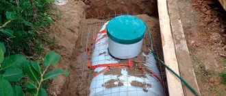
Storage well installation diagram
When designing, preference should be given to sealed wells without the possibility of discharge of runoff into groundwater. This is especially important since it is almost impossible to independently determine the type of soil and the depth of groundwater flow.
If a brick or reinforced concrete well is chosen, then a foundation must be made for it, which significantly increases the cost of construction work.
In addition, digging a hole for the foundation and for installing the well itself is only possible with the help of heavy equipment (excavator).
SNiP requirements for sewer wells ↑
Sewage facilities have been used by people for hundreds of years. It is quite logical that the technology for their arrangement during this period was worked out to the smallest detail. Clear requirements and instructions for the construction of treatment facilities are given in SNiP2.04.03-85 “Sewerage. External networks and structures.”
The document states that when installing a septic tank in a private household, an inspection well must be installed between the outlet of the internal sewage system from the house and the receiving chamber of the treatment device.
For post-treatment and disposal of wastewater after a septic tank, it is recommended to also equip a filtration tank
According to SNiP, inspection wells must be installed at connection points in the case of connecting a local sewerage system to the central collector, as well as:
- on long straight sections of pipelines;
- when turning the pipeline and at the entry points of branches;
- when the slope of the location or diameter of the pipes changes.
Attention! If the diameter of the external sewerage pipes reaches 150 mm, the distance between the tanks should be 35 meters; if the cross-sectional size of the pipes is 200 mm, the distance is increased to 50 meters.
As for filtration and storage wells, other location standards apply. They are based on maintaining the distance of the well from significant objects in nearby areas:
- 1 meter to outbuildings;
- 5 meters to the foundation of a residential building;
- 3 meters to the fence and the highway;
- 20 meters to planting garden crops;
- 30 meters to a pond or well with drinking water.
The current standards are designed to prevent the release of untreated wastewater into the soil, which can occur as a result of the failure of a treatment plant.
Dimensions of structures ↑
SNiP also imposes a number of requirements on the design of a treatment device for autonomous sewerage. The inspection tank must include four main elements:
- Mine.
- Working chamber.
- Neck.
- Protective cover.
Dimensions of reinforced concrete rings used in the construction of sewer wells
The shape of the protective cap is determined by the geometric dimensions of the neck. When arranging treatment facilities, round hatches are traditionally installed. The dimensions and overall characteristics of external hatches are regulated by GOST 3634 99. The key criterion when choosing the shape and size of a product is its scope of application.
Table of standard sizes of round hatches
When constructing autonomous sewer wells, plastic or cast iron hatches with a diameter of 450-550 mm are used.
The parameters of concrete filtration structures vary within the following limits:
- Inner diameter 1000/1250/1500/2000 mm;
- The height of the elements is from 2410 mm to 2870 mm.
The dimensions of round filter tanks are 1.5-2 meters with a burial depth of 2.5 meters. The dimensions of rectangular containers are on average 2x2.8 meters.
The cross-section of the shaft must be such that a person can freely descend into the well and, if necessary, carry out cleaning of the system and maintenance of sewer pipes. The height of the working part of the manhole is determined based on the height of the person and is on average 1.8 meters.
The depth of the storage tank pit should also not exceed 2.5 meters
The diameter of the pit for the treatment facility should be half a meter larger than the size of the well. A distance of 60-70 cm is maintained between the lower part of the sewer pipe and the level of the bottom of the pit. If the groundwater level is high, waterproofing must be laid when constructing a sewer well.
Diameters of treatment facilities ↑
Current standards also regulate the size of tanks. This parameter directly depends on the diameter of the laid pipeline.
The diameter of sewer wells according to SNiP should be:
- on pipelines with a cross-sectional area of up to 150 mm - from 70 mm and above;
- on pipes with a diameter of up to 600 mm – 1000 mm;
- with a pipe size of 700 mm - 1250 mm;
- when connecting pipes measuring 800-1000 mm - designs D 1500 mm;.
- on pipelines of 1200 mm and above - 2000 mm.
When constructing square-shaped wells, the length of each side of the tank must be at least 1 meter.
Material of manufacture ↑
A number of requirements are imposed by the current regulatory document on the material for the manufacture of sewer wells.
Treatment facilities must have high strength and tightness parameters
When constructing sewer wells, it is permissible to use:
- Production sample plastic structures. Manufactured in full compliance with GOST standards. The consumer’s task is to choose a product of optimal size.
- Concrete rings. Reinforced concrete products are also produced by factories in accordance with current GOSTs and are offered for sale in a wide range.
- Rubble or brick. Moisture-resistant materials are used in the construction of sewer wells on their own. But due to the complexity of installation, moisture-resistant brick and rubble stone are used much less frequently.
The main advantage of plastic structures is that they are produced already equipped with outlets, the dimensions of which clearly correspond to the standards of pipes made of any type of material: plastic, asbestos, cement. Production sample shafts can be connected to any sewage system within 15-20 minutes immediately after installation.
Design and structure of sewer wells
The design of a sewer well usually has a standard structure.
This:
- Manhole cover (located on the surface of the sewer well).
- Neck.
- Working chamber.
- Mine.
- Bottom.
Depending on the material from which the sewer well is made, the sizes and shapes of its structured parts can vary significantly.
Design for sewer wells
The type of underground chamber is also determined independently, depending on the type of underground communications.
Such wells and their sizes are determined in accordance with the requirements for servicing communications adjacent to this well.
Typically, a sewer well has a working chamber height of 1.8 meters.
The sewer well shaft, as a rule, has a circular cross-section and is equipped with a special ladder to make it convenient to descend into it.
All sewer wells must be covered with a special cover. It is needed to prevent foreign objects, including dirt and debris, from getting inside the well, as well as for the safety of people.
Very often in the media they talk about people and animals falling into a well that is not covered with a special lid. Therefore, neglecting the installation of a special cover on installed sewer wells is not advisable and is strictly prohibited.
The working part as a structural element of the well
The working part of the well, mounted using wall rings, has a height of 1.8 m. The size of the internal diameter of the KS Dv is 1000-2000 mm, which is determined by the diameter of the pipes.
The rings are installed on the leveled surface of the tray. The minimum dimensions of the working part of the well, depending on its type, are subject to the following requirements:
- height - not less than 900 mm;
- shaft diameter is 150-200 mm with a pipe diameter of no more than 70 mm.
The height of the working part of the well varies between 1.0-2.8 m. The transition to the neck from the working chamber of the structure is carried out using a floor slab (PP), the thickness of which is 100 mm. It has a hole with a diameter of 700 mm.
Installation of the neck is carried out using wall rings (WR) with internal and external diameters equal to 700 mm and 840 mm.
To protect the well from contamination and insulate it, an additional cover made of wood or metal should be installed in the tray part of the support ring.
Brackets in the working part coated with anti-corrosion varnish are provided for lowering workers into the structure.
For their manufacture, reinforcing steel is used, the diameter of which is 16-19 mm. They must be firmly embedded in the walls of the wells.
The initial bracket is installed at a height of 0.7 m from the very top of the structure. Next, the staples are placed down in a checkerboard pattern.
In this case, the distance between them is taken into account, equal to 0.30 - 0.35 m. The width of the running brackets when they extend from the walls of the structure at 0.12 - 0.15 m should be 0.15 m. The horizontal distance between the rows of running brackets is provided equal to 0.15 m.
Construction of an observation structure
There are different types of sewer chambers, the choice of which depends on their purpose.
When constructing a well for wastewater, you will need to install a special tank, which is large in size, suitable for human growth.
All sewage must flow into a special chamber of the sewer well, for which a pipeline is connected to the working part. Any type of structure installed on a wastewater route provides the following schematic diagram:
- The bottom, which is the lower part of the working chamber, where the direct treatment of sewage occurs.
- A shaft or cavity for carrying out inspection or repair work inside the chamber, providing a ladder or walking brackets for lowering and lifting.
- The neck required to enter the working part, which has a cover with a hole for the hatch.
- The working part, which is a space inside the well intended for the accumulation of wastewater that requires periodic pumping along with sewage.
- A hatch is an element of the well cover or a closing link in the system, which helps prevent precipitation, debris and foreign objects from entering the working chamber.
Construction of a well requires digging pits or drilling wells, since the working part must be underground.
For the arrangement of waste chambers or working parts, the same materials are used as for the installation of other types of tanks for sewer systems:
- concrete;
- brick;
- plastic, etc.
According to regulatory documents, the diameter of the well neck is 700 mm. To move from it to the working chamber, it is necessary to install a conical part or a reinforced concrete floor slab.
If the structures are located at a distance of 300-500 m, then the size of the neck should be sufficient to lower various cleaning devices into the chamber.
The hatches provided in the lid to close the neck can be light or heavy. The latter are often installed on roadways where the road surface is of the highest quality. The requirements for the location of the hatch, according to regulatory documents, are as follows:
- in green areas - 50-70 mm above the soil level;
- in undeveloped areas - 200 mm above the soil level.
In areas without a road surface, a blind area around the hatch is required. This will ensure water drainage.
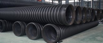
To create storm drains of modern models, high-quality polyethylene or polypropylene is used.
These materials are used to make double-walled pipes with a rigid surface.
The use of these pipes makes it possible to cope with various loads associated with displacement or freezing of the soil, and the movement of groundwater.
The structures of inspection and service wells are equipped with a hatch.
They provide for a neck having a width of 630-800 mm. GOST requires the installation of round wells, the working part of which includes reinforced concrete rings, which represent a reservoir for the pipeline.
To create structural elements of the manhole, elements are used that are manufactured in accordance with GOST 8020-68 in the factory.
The working part can consist of CS or wall rings with the following dimensions of internal and external diameters (DvxD):
- 700x840 mm;
- 1000x1100 mm;
- 1500x1680 mm;
- 2000x2200 mm.
The inner and outer diameters of the support rings (OK) are 660 mm and 840 mm, respectively. The thickness of the concrete adjustment stones is 65 mm. The height of the hatch installed above the neck is 175 mm. It is laid flush with the road surface.
Technological part of the inspection well
Concrete or reinforced concrete well slabs are laid on a crushed stone base.
The main technological element of the structure is a tray made of monolithic concrete grade M200.
The installation of the structure is carried out using formwork templates, which require grouting the surface with a cement solution and subsequent ironing.
The pipeline in the working chamber of the well usually goes into a tray.
Linear structures are equipped with straight trays, the surface of which in the lower part should repeat the surface inside the pipe. The upper part provides for a vertical surface.
The slope of the shelves formed on both sides of the tray towards it is 0.02°. Since the shelves are located in the working part of the well, they serve as platforms where workers involved in carrying out technical activities can fit. The dimensions of the working part at a height of 1800 mm vary. They are selected taking into account the pipe diameter (d):
- d=600 mm - 1000 mm;
- d=800 mm - 1000-1500 mm;
- d=1200 mm - 2000 mm.
The working parts of rectangular wells depend on the diameter of the pipes (d), the size of which is large:
- with d=700 mm - 1000 mm;
- with d>700 mm, the length of the structure along the axis of the pipeline is d+400 mm, and the width is d+500 mm.
The radius of rotation of the tray axis inside the structure should not be less than the diameter of the pipes. The channel for connecting the side branch in the junction structure is made curved, having the same radius of rotation in the direction of movement of the drains.
For larger collector structures with a diameter of 1200 mm or more, a turning radius of at least 5 pipeline diameters is provided. Installation of inspection type wells is carried out at the beginning and end of the turning curve.