Translation from the Electric DIY Lab website
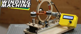
Hello everyone, I present to you a machine I made for winding toroidal coils based on Arduino. The machine automatically winds the wire and rotates the toroid. I used an encoder and a 16×2 LCD screen as the interface. The user can enter parameters such as coil diameter, number of turns and winding angle.
In this article I will tell you how to build this machine and give details of its operation.
Everything is described in detail in the video - you can watch it or read the article.
Assembly Details
Winding ring
I made the ring from 12 mm plywood. External diameter – 145 mm, internal – 122 mm. There is a recess 43 mm long and 5 mm deep for the coil.
I made one cut in the ring and a lock to open it. Having opened the lock, we place the toroidal coil inside the ring.
The ring also has a recess on the outside, 8 mm wide and 4 mm deep, which accommodates a 6 mm wide belt.
Coil
A spool of copper wire that I machined from a nylon rod. All sizes are shown in the picture.
The material was chosen because nylon, firstly, is lighter than aluminum, and secondly, it is easy to sharpen on a machine. Also, when the machine is running, it doesn't fluctuate as much.
Machine body
The body is also made of 12 mm plywood. Three guide rollers are attached to it, spaced approximately 120° from each other.
The rollers are made from 626Z bearings, nuts and bolts. Our wooden winding ring will rotate on them.
The upper part of the ring folds back and, after closing, is clamped using a wing nut. Having folded this part, we install the ring inside the machine. Having returned it to its place, you need to press the roller against it so that it fits into the groove.
Toroid holder rollers
This is a roller that rotates the reel and at the same time holds it. I turned them from nylon rod on my mini lathe. All sizes are shown in the photo.
I equipped the rollers with foam tape; it holds the reel well and does not slip. It is important to use wing nuts to secure the guides - regular ones are unscrewed due to vibration.
I placed a flange bearing on the top and bottom of each roller.
Stepper motor mount
This is how I mounted the stepper motor, NEMA17. It rotates the reel, which allows you to automatically wind the wire around its entire circumference and does not require manual rotation.
DC motor
This motor rotates the winding ring. I used Orange Jhonson 12v Dc Motor 300 RPM. I advise you to take a 600 RPM or 1000 RPM motor.
The belt is 600 mm long and 6 mm wide. The motor holder attached to the aluminum profile is also made of plywood.
Infrared sensor
Your browser does not support HTML5 video.
I used a sensor from SeedStudio. It sends a signal to the Arduino's interrupt pin so the Arduino can count the number of revolutions of the ring.
I mounted the sensor on an aluminum profile so that the ring lock also acts as a reflective surface to which the sensor responds.
This sensor produces 2 signals per rotation of the ring - when wood is replaced by metal, the signal changes from low voltage to high voltage, and then vice versa. The interrupt handler registers two state changes. Therefore, to calculate the actual number of turns, I had to divide the number of operations in half.
Apparatus base
The base is also made of 12 mm plywood and has dimensions of 300x200 mm. Four rubber feet will hold the machine firmly and well, and help avoid unnecessary vibration.
To install the components, I attached an aluminum profile to the base. I love it for its flexibility in use. All components can be easily installed on the profile and moved along it. Allows you to easily align components relative to each other.
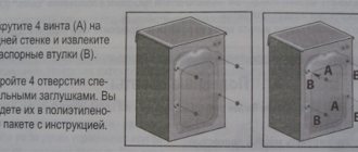
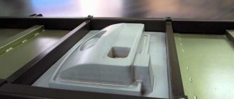
Controller housing
The box is printed on a 3D printer, with a board, LCD display and encoder installed inside. The case gives a professional look to the entire project, and also allows for convenient setup of the device. The housing is secured to the base using a metal bracket.
Connection diagram
Design and operating principle
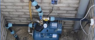
The design feature of such a transformer lies in the shape of the magnetic circuit, which represents a closed ring, called a torus.
Otherwise, the composition of its elements is identical to other types of electrical machines:
- Winding - made with a copper conductor, divided into primary and secondary. Both windings may differ in conductor cross-section.
- Toroidal core - has the shape of a ring, is made by typesetting, strip steel or monolithic iron, depending on the dimensions and purpose. The material used is ferromagnetic alloys, which provide good magnetic conductivity.
- Insulating materials - part of the dielectric is pre-applied to the installation wires, the rest of the dielectric is separated by the torus coil with the iron, the windings among themselves, between the coils and the casing. Tape or varnished fabric materials, electrical insulating cardboard, glue, etc. are used as insulation.
- Protective casing - designed both to protect the power transformer from mechanical damage and to prevent human contact with the surface of the windings.
- Conclusions of the secondary and network windings , fasteners and auxiliary parts.
Rice.
1. Design of a toroidal transformer The principle of operation of a toroidal transformer is to supply voltage to the terminals of the primary winding. After which an electric current begins to flow in it, which creates a magnetic flux inside the turns. The magnetic flux moves inside the coil frames and induces an emf in the secondary winding. If a load is connected to its terminals, the specified power will be consumed.
This device has found application in toroidal autotransformers (LATRs), radio electronics, welding transformers and other converters. At home, they rewind this type of transformer through a relatively simple process.
Transformer Winding Tools
First of all, you should think about making your work easier with the help of various devices. In the factory production of transformers, they are made, of course, using special machines, and not by hand.
It hardly makes sense for an amateur to think about a machine, but simple devices to make work easier will certainly pay off.
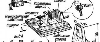
The simplest option is two posts attached to a wooden board, and a metal rod between them, curved on one side in the shape of a handle. Externally, it looks like a spit. The rod is threaded through the holes in the racks, usually no more than 1 cm thick. The axis of the “skewer” must be threaded through the frame of the future transformer (we do not stop at its manufacture, since its type and features depend on the intended function of the device). Typically, a wooden block with a hole for the axle and a size suitable for the frame is used for this.
Diagram of a machine for winding transformers.
If you have a hand drill, the task becomes easier. The drill is securely attached parallel to the table (you can simply clamp it in a vice) so that its handle can rotate freely. A metal rod is inserted into the drill chuck with a block mounted on it, on which the transformer frame is fixed. Ideally, the rod should be threaded, then the block can be easily fixed by simply clamping it on both sides with nuts. In some cases, it is possible to do without a block altogether, clamping the frame either with the nuts themselves, or with wooden planks or textolite plates.
You can use a telephone inductor, a machine for textile bobbins, a device for rewinding film and other similar mechanisms as a winding mechanism. The key point is the “soft”, without jerks, progress of the process.
In addition, you will also need an unwinding device (especially if you are using an old transformer as a wire source). Its stroke should also be uniform, so as not to complicate the process of winding a new transformer, and also not to damage the wire insulation. Typically, the unwinding device is made in a similar way to the winding device, but a handle for rotation is optional.
An additional device for counting the number of turns may also be useful. You can get by with an oral count, when each turn (or a couple of turns) is counted, and every hundred is marked on paper. If you use a machine with a gear drive, you should not forget about the gear ratio.
However, you can use some kind of device. A water meter, an electric meter, and a bicycle speedometer are suitable. The meter is connected to the winding machine using a flexible roller (a rubber tube with fairly thick walls) or gears.
DIY winding machine
One possible option is to make a machine equipped with an adjustable stacker and a thread counter, using the principle of a bicycle wheel.
The wheel is placed on a pin in the wall, and its rim is equipped with a rubber ring. In order to put the core on the rim, you will first need to cut it and then fasten it again, obtaining a solid circle. Having wound the required length of wire around it, one end of it is connected to a core freely located on the rim. The coil moves along the rim in complete circles, as a result of which the wire is laid on the frame. In this case, a bicycle counter is used to count revolutions.
Creating a more advanced device will require the use of stepper motors with positioning of their position. For this, microcontrollers and an electronic counter are used. Such design requires certain skills in radio electronics.
Self-production
The price of finished products is high, and it is not always possible to find a device with the required parameters. Therefore, it is advisable to make a transformer or autotransformer with your own hands. In addition to making a transformer from scratch, it is possible to rewind a faulty device.
To manufacture the product you will need transformer hardware and wire. Iron consists of plates assembled in the form of a torus and forming a magnetic circuit. You can buy it or take it from old disassembled devices. For example, take plates from industrial transformers and, using a device in the form of a cut ring, roll the metal into donut-shaped plates. Assemble the plates, cover the core with fiberglass and fill it with varnish.
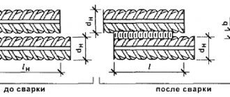
The turns of the windings are made of copper wire of the required diameter. The winding itself is not difficult:
If a retraction is necessary during the winding process, then the wire being wound is broken. A tap is soldered to the break site, and the main wire is wound further. The outlet site is usually carefully isolated. Fastening the ends of the windings is usually done using threads that tie the wires to the surface of the core or laid wire. It is better to place the strip of wire being threaded on the “shuttle”. It is made from a small plastic profile with slots in the ends for fixing the wire.
Such work requires care and precision, especially when winding the primary winding. To manufacture several devices, it is advisable to use a machine for winding toroidal transformers. It is difficult to make such a device with your own hands, but it is possible.
DIY winding machine
In the last article, I shared with you how to rewind the secondary windings of a transformer to the required voltage. The thick wire was wound manually, since it was not possible to carefully lay the coil to the coil in any other way at home. With a smaller diameter of the winding wire, a more technologically advanced method can be used, which will reduce the time and effort during winding, and also, which is important, the manufacture of the transformer will not differ from the factory version. Next, we will describe the simple design of a homemade winding machine, with which you can easily wind coils, chokes, power and sound transformers.
Principle of operation
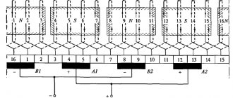
The simplest toroidal transformer consists of two windings on a ring and a steel core. The primary winding is connected to a source of electric current, and the secondary winding is connected to a consumer of electricity. Due to the magnetic circuit, the individual windings are connected to each other and their inductive coupling is strengthened. When the power is turned on, an alternating magnetic flux is created in the primary winding. Meshing with individual windings, this flux creates an electromagnetic force in them, which depends on the number of turns of the winding. If you change the number of windings, you can make a transformer to convert any voltage.
Photo - Operating principle
Also, converters of this type are either buck or boost. A toroidal step-down transformer has a high voltage on the secondary winding terminals and a low voltage on the primary winding. Increasing is the opposite. In addition, the windings can be of higher or lower voltage, depending on the characteristics of the network.
Revolution counter for counting turns
One revolution is equal to one turn - this is how I used to calculate in my head when winding a transformer on a primitive device. With the advent of a full-fledged winding machine with a counter provided, it became much easier, but the most important thing is that when winding turns, the error rate was reduced to almost zero.
The winder under consideration uses a mechanical counter UGN-1 (SO-35) from Soviet equipment. It can be replaced with a bicycle meter or a mechanical counter from an old household tape recorder, where it measured tape consumption. You can also assemble a simple meter with your own hands, having only a calculator, a reed switch, two wires and a magnet.
Disassemble the calculator into two contacts closed by the “equal” button, solder two wires, and solder a reed switch to the ends of the wires. If you bring a magnet to the reed switch, its plates inside the glass flask will close and the calculator will simulate pressing a button. Using the 1+1 addition function of the calculator, you can count the revolutions.
Next, we attach the homemade disk to the first axis. We glue a magnet to the disk, and attach a reed switch to the machine body or bracket. We position the reed switch so that when the disk rotates, the magnet passes next to the reed switch and closes its contacts.
Using this principle, you can replace the reed switch with a limit switch, and make the disk in the form of an eccentric. The eccentric disk, rotating with its convex part, will press on the limit switch
Menu navigation
The LCD display is used for output and the encoder is used for input.
First welcome screen.
On the second screen you need to enter the outer diameter of the coil - the device supports coils of different diameters.
On the third screen you need to enter the number of turns.
On the fourth screen you need to enter the coil coverage angle. 360° means that the entire coil will be covered with wire. 720° means that the coil will be wrapped with wire twice around the circumference.
On the 5th screen you can check all input data before starting the machine. If everything is correct, press the encoder and the machine starts.
The 6th screen shows the number of turns in real time.
The 7th screen appears when work is completed.
Oops, your banner ran away!
Reading now
Editorial Digest
We send the best articles once a month
A letter will be sent to this address soon. Confirm your subscription if everything is valid.