Translation from the Electric DIY Lab website
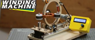
Hello everyone, I present to you a machine I made for winding toroidal coils based on Arduino. The machine automatically winds the wire and rotates the toroid. I used an encoder and a 16×2 LCD screen as the interface. The user can enter parameters such as coil diameter, number of turns and winding angle.
In this article I will tell you how to build this machine and give details of its operation.
Everything is described in detail in the video - you can watch it or read the article.
Assembly Details
Winding ring
I made the ring from 12 mm plywood. External diameter – 145 mm, internal – 122 mm. There is a recess 43 mm long and 5 mm deep for the coil.
I made one cut in the ring and a lock to open it. Having opened the lock, we place the toroidal coil inside the ring.
The ring also has a recess on the outside, 8 mm wide and 4 mm deep, which accommodates a 6 mm wide belt.
Coil
A spool of copper wire that I machined from a nylon rod. All sizes are shown in the picture.
The material was chosen because nylon, firstly, is lighter than aluminum, and secondly, it is easy to sharpen on a machine. Also, when the machine is running, it doesn't fluctuate as much.
Machine body
The body is also made of 12 mm plywood. Three guide rollers are attached to it, spaced approximately 120° from each other.
The rollers are made from 626Z bearings, nuts and bolts. Our wooden winding ring will rotate on them.
The upper part of the ring folds back and, after closing, is clamped using a wing nut. Having folded this part, we install the ring inside the machine. Having returned it to its place, you need to press the roller against it so that it fits into the groove.
Toroid holder rollers
This is a roller that rotates the reel and at the same time holds it. I turned them from nylon rod on my mini lathe. All sizes are shown in the photo.
I equipped the rollers with foam tape; it holds the reel well and does not slip. It is important to use wing nuts to secure the guides - regular ones are unscrewed due to vibration.
I placed a flange bearing on the top and bottom of each roller.
Stepper motor mount
This is how I mounted the stepper motor, NEMA17. It rotates the reel, which allows you to automatically wind the wire around its entire circumference and does not require manual rotation.
DC motor
This motor rotates the winding ring. I used Orange Jhonson 12v Dc Motor 300 RPM. I advise you to take a 600 RPM or 1000 RPM motor.
The belt is 600 mm long and 6 mm wide. The motor holder attached to the aluminum profile is also made of plywood.
Infrared sensor
Your browser does not support HTML5 video.
I used a sensor from SeedStudio. It sends a signal to the Arduino's interrupt pin so the Arduino can count the number of revolutions of the ring.
I mounted the sensor on an aluminum profile so that the ring lock also acts as a reflective surface to which the sensor responds.
This sensor produces 2 signals per rotation of the ring - when wood is replaced by metal, the signal changes from low voltage to high voltage, and then vice versa. The interrupt handler registers two state changes. Therefore, to calculate the actual number of turns, I had to divide the number of operations in half.
Apparatus base
The base is also made of 12 mm plywood and has dimensions of 300x200 mm. Four rubber feet will hold the machine firmly and well, and help avoid unnecessary vibration.
To install the components, I attached an aluminum profile to the base. I love it for its flexibility in use. All components can be easily installed on the profile and moved along it. Allows you to easily align components relative to each other.
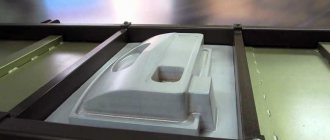
Controller housing
The box is printed on a 3D printer, with a board, LCD display and encoder installed inside. The case gives a professional look to the entire project, and also allows for convenient setup of the device. The housing is secured to the base using a metal bracket.
Connection diagram
Wire laying device
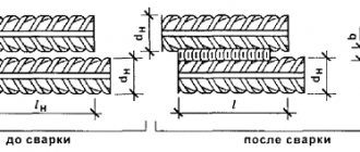
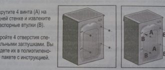
The process of distributing long material is carried out using three plates connected to each other. A 6 mm hole is drilled in the upper part of the structure being created. It is used to install the screw:
- Bushings with a diameter and length of 20 mm are installed in the plates.
- The outer elements are connected by gluing the leather gutter. They are required to align and tension the coils.
- A steel rod with threads is attached to the top. It is designed to hold plates together.
- You can simplify the process by installing a folding bracket.
A homemade winding machine is characterized by great efficiency. The winding device can be made quite simply even using simple materials and tools.
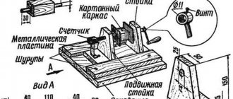
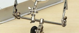
Manufacturing of turns counter
Sometimes it is very important to know the number of turns laid. To do this, you need to install a special device that you can make yourself. Among the features, the following should be highlighted:
- An ordinary electric magnet is attached to the upper ball.
- An insulated wire is connected to one side.
- The lead-out contacts are connected to a special calculator.
- The coil with wire is placed separately.
Due to this arrangement of the main elements, the counter is compact and very effective in use. A winding machine with a homemade device for counting turns gives a small error, which also needs to be taken into account.
Winding machine mechanism
The winding machine is classified into groups:
Each product has an individual design.
A winding machine that performs row laying of wire consists of the following elements:
The standard model of a device for laying wires with several bends in one turn assumes the presence of the following elements:
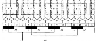
Winding of wire onto toroidal cores is carried out using specialized ring-type equipment:
Winding machine on Arduino version 2.0
More than a year has passed since the publication of the first version of the winding machine on Arduino. Since then, I have rethought some important points in the mechanics, electronics and control program, and in this article I will talk about the implementation of update 2.0. In terms of the basic design and electrical circuit, both versions are very similar and, in order not to repeat myself, I will make references to the first article and recommend that the dear reader familiarize himself with it before reading this one.
During the discussion on the forum and working with the machine, one of the main problems was identified in the “jerky” auto-winding mode, when the main engine had to stop while the stacker was operating, which led to wire jerking and loosening of the entire structure. In addition to the previous one, there was no acceleration of the main engine, which further aggravated the situation. The second problem was the extremely inconvenient way to install and remove the mandrel on which winding was carried out. To do this, it was necessary to disassemble the entire winding axis, which made the work extremely difficult.
So, first things first. The operating program for both stepper motors is now organized in one interrupt, which makes it possible to “steer” them simultaneously. At the same time, for better density of turns, the stacker motor makes a movement at the end of the turn cycle, which allows you to press a new turn closer to the previous one. In addition, the main engine reaches a given speed with acceleration, or more precisely, it starts moving at a certain speed Vo≈4 rpm and accelerates per revolution to the given one. This reduces the wire jerk at the beginning of winding. The “Speed” menu parameter now sets the speed in revolutions per minute, the software limit is 300 rpm, although I did not test speeds even close to the limit during real winding, because To do this, it is necessary to exclude all or almost all plastic parts from the mechanics. A Direction parameter has been added to the auto-winding menu, which specifies the initial direction of the stacker.
In connection with the use of the SD 23HS5628, power is now provided by an LRS-75-24 power supply with an output of 24 Volts, the driver for the large motor is now TB6600, and for the small one the same DRV8825 is left. Read the previous article about setting the current on the DRV8825. The microcontroller control pins for the drivers remain unchanged. If a CNC Shield is installed, there will be an "A" axis for the stacker and a "Z" axis for the winder motor. The KP08 bearings have been replaced with KFL08, but this is specific and both options are quite functional.
Winding machine operating method
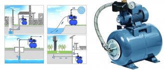
A winding machine is a popular equipment with which transformer single-layer and multilayer cylindrical coils and all kinds of chokes are wound. The winding device evenly distributes the winding wire with a certain tension level. It can be manual or automatic, and works on the following principle:
The manual device for laying wires is quite primitive, so it is rarely used in production.
A mechanically driven winding machine allows you to perform complex winding:
It operates using an electric motor that drives the intermediate shaft using a belt drive and three-speed pulleys. The friction clutch plays a big role in this. Thanks to it, the machine operates smoothly, without shocks or wire breaks. A spindle with a fixed frame, on which a coil is placed, starts the counter. The winding machine is adjusted using a screw to any width of the reel frame.
Modern models are equipped with digital equipment. They work through a specially defined program that stores information in a storage device. The value of the length and diameter of the wire allows you to accurately determine the point of intersection of the lines.