Casting alloys: about the main technological properties
The first among them is fluidity. This means that the molten material spreads through the channels of the casting mold and fills the contours. Thanks to this property, the latter are reproduced with maximum clarity.
Using special tests, it is determined whether the property of fluidity is present or not. The measurements take the length of the completed Archimedes spiral.
The minimum wall thickness of the casting is selected depending on the fluidity:
- 3.4 mm for small castings from midrange in sand molds.
- 8-10 mm in the case of medium dimensions.
- 12-15 – for large ones.
The remaining castings are produced with a thickness of 5-7, 10-12 or 12-20 mm.
Don't forget about shrinkage. This name was given to the process in which the casting decreases in volume during cooling. It all starts in the mold, with the metal in liquid form. And until the ambient temperature rises.
Different materials have different levels of shrinkage. To determine it, the following factors become important:
- Chemical composition.
- Filling temperature.
- Workpiece configuration.
The standard value is between 1.9% and 2.1%.
To avoid the formation of large stresses and cracks, it is important to ensure the preservation of the following properties:
- Uniform wall thickness.
- Smooth transitions.
- Normal radii of mating surfaces.
- Elimination of elements that complicate shrinkage.
Rods and materials must have increased flexibility to achieve better results.
Gas absorption is the ability to dissolve various gases that cast alloys may have in the molten state. The solubility of gases decreases when they are in a solid state and then cooled. Because of this, defects appear in the castings in the form of gas shells and pores.
There is a concept of segregation - it is used for heterogeneity of composition in different parts of the casting. It can be dendritic or zonal.
Dendritic occurs within a single nucleus.
Zonal is called heterogeneity that manifests itself throughout the entire volume of the casting.
Castings are made using the following several methods:
- Centrifugal casting.
- Injection molding.
- In the chill mold.
- In forms with special shells.
- According to lost wax models.
- In sand forms.
There are so-called special casting methods:
- Compositional.
- Using magnetic fields.
- Suspension.
- Electroslag centrifugal.
About sand casting
Foundry production is aimed at producing castings. These are cast metal products that are produced by pouring metals in molten form into special casting molds. Then comes solidification, acquisition of specific outlines.
Technological equipment for casting
Foundry equipment is special devices that are used to produce the necessary products with the required characteristics. Example - flasks, core boxes, sub-model slabs, models, and so on.
Let's start with the models. This is the name of the devices with the help of which impressions of the cavity are obtained that correspond to the external configurations of the casting. During assembly, rods are installed in the mold, which contribute to the formation of holes and cavities inside the castings and other contours with complex dimensions.
Initially, models are made larger than castings to take into account the amount of linear shrinkage characteristic of the alloy. The size of allowances is taken into account when machining castings. Allowance is the layer of metal that is removed during such work. It is determined by the size of the castings and the types of alloy. Compared to the side and top parts of the structure, the allowance for the top should be slightly larger. This is due to the appearance of accumulations at the top in the form of gas inclusions, particles of the molding sand, and slag. Some problems arise when removing the core mixture, sintered inside, from small holes. During subsequent mechanical processing, this negatively affects the durability of the cutting tool. It is recommended to use casting to make holes whose diameter is in the range of 25-30 mm.
The molding slopes depend on the height of the casting. They are added to models to make it easier to remove them from the mold. Surfaces are subjected to treatment. Forms may be destroyed during removal if there are no slopes. And the molding mixture itself most likely simply crumbles.
Signs are the names of the protruding parts of the model, with the help of which prints of the sign parts of the rods are obtained. The main thing is the absence of slopes and sharp corners in places where the walls of the castings meet.
The term fillet is applied to rounded internal corners. External ones suggest the use of the name “rounding”.
The following types of materials are used for models:
- Plastic.
- Metal alloys.
- Wood.
In the case of wood, use a well-dried base, made of beech or ash, pine. The product is glued together from individual blocks, rather than from a single piece, this prevents warping. At the same time, they adhere to different directions for the fibers that make up the product. But such designs cannot boast of durability.
A clean working surface and high precision are the main advantages of metal analogues, in addition to increased service life. Aluminum alloys with reduced density are used in production. This material does not oxidize and can be processed by cutting.
Light weight, protection against warping, and resistance to moisture are the main advantages of plastic models. One of the promising areas is the use of foamed polystyrene. It does not need to be removed from the mold before pouring; the material is gasified while the work is being done.
For the manufacture of cores, special core boxes are used. They provide increased speed when removing the rod and make the mixture compact evenly. They differ in the presence of slopes, which makes them look like models. The design is either one-piece or detachable, and the materials used in production are the same as the models.
Opokami are frames of various shapes made of metal. Their main purpose is the use of molding sands for the manufacture of foundry molds. The following types of materials are used in production:
- Steel.
- Cast iron.
- Aluminum alloys.
They are assembled from separate parts and can be cast or welded. To reduce weight, walls are often made with additional holes. This simplifies the removal of gases and promotes better bonding between structural elements. Staples and other similar devices are used for fastening.
About molding and core mixtures
Foundry production involves the widespread use of clay and other mixtures to produce castings with different shapes. There are one-time forms in which you can only receive one product at a time. The mold is destroyed when the finished part is removed or knocked out.
For molding and core mixtures, it is important to have certain characteristics. It is worth taking a closer look at some of them.
Gas permeability.
Due to porosity, many mixtures allow gases to pass through the walls of the mold. Molten forms of metals always contain a dissolved form of gases, which are released as they cool and solidify. When heated, gases are also released in large quantities from the molding materials themselves. Gas bubbles or cavities appear in the body of the product if gas permeability is insufficient.
Non-stick.
With this property, the mixture is able to withstand high temperatures for a long time without entering into chemical reactions with them or melting. The quality of the surface deteriorates due to burnt films, in which case further surface treatment is difficult. Gas permeability begins to decrease sharply if the material melts.
Compliance.
The name for the ability of a mixture to reduce its volume when exposed to metal shrinkage. The casting is produced with stresses if this characteristic is not enough. The result is the formation of cracks in the future.
Plastic.
Preserve the resulting shape with the mixture, perceive the outlines of the model or core box.
Surface strength or crumbling.
The way the mixture resists the abrasive effects of a metal jet. If the level is insufficient, the particles of the molding sand separate from each other and enter the casting.
Strength.
Maintaining its shape without breaking while it is being prepared and processed. Even strong shocks during assembly and transportation should not lead to the rapid appearance of defects. The pressure of the metal being poured must also be maintained.
Core and molding materials are equally made from artificial or natural sources. The basis for most mixtures is sand. In most cases, the quartz variety, consisting of silica, is chosen. It is fireproof, hard and durable material. For small castings, varieties of fine-grained compositions are used. Thanks to this, the molding mixture boasts gas permeability.
Zircon sand, chromite and some other materials are rarely used in the manufacture of parts. These are expensive analogues, although they are better than quartz sand in terms of thermal conductivity and thermochemical stability. An example of the purpose of such bases is large steel castings with a clean surface, when maintaining certain characteristics becomes especially important.
The second source material for molding sands can be called clay. This is a binder that helps maintain strength and ductility. Bentonite and kaolinite varieties of composition are widespread. Hydride shells of water molecules form on the surface of clay particles in the presence of moisture. After this treatment, the adhesion of the material improves and easy gliding is ensured. The binding ability of clay becomes better if it holds more water on the surface, and the plasticity of the molding sand is also better in this case. The strength of the mixture increases as water is removed from the surface.
Not only clay, but also other components can act as binders for molding sands:
- Sulfite-alcohol stillage.
- Dextrin.
- Resins of synthetic origin.
- Liquid soap, and so on.
Such substances are included in the composition in an amount of 1.5-2%. Once cured, it takes much less time.
Other additives are also added to sand-clay mixtures to improve the initial qualities. Example of non-stick materials for steel casting:
- Chromium iron ore.
- Dust-like quartz.
Coal dust and fuel oil are used in the case of cast iron and non-ferrous castings. Sawdust is added to increase gas permeability and pliability.
Molding sands can be divided into several groups according to the nature of their use:
- United.
- Fillers.
- Facing.
They can be wet or dry depending on the condition of the casting mold during its manufacture.
Depending on the casting alloy, the composition of the molding sand is chosen. Factors such as melting and shrinkage temperatures, weight and dimensions, and casting configuration are taken into account.
A thin layer of non-stick materials is used to prevent burning and improve surface cleanliness. Dusts are used in the case of raw molds.
Molds for cast iron castings involve the use of:
Powdered mixture of magnesium oxide.
Charcoal.
Concrete.
Powdered graphite.
In the case of steel castings, the main mixture consists of other components:
- Zircon.
- Dust-like quartz.
- Fire-clay.
- Magnesium oxide and other similar materials.
Non-stick paints are relevant when it comes to dry forms. It is permissible to add aqueous suspensions of materials together with binders.
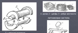
Gating systems
When pouring metals, the so-called gating system is used. This is a set of channels and reservoirs through which the alloy enters the mold cavity from the ladle. The gating system works to force the metal into the mold and the process is continuous. Other stages of work are also provided:
- Feeding the casting to compensate for shrinkage.
- Protection from further damage in the form.
- Protection against ingress of slag and air jets.
Any gating system consists of the following components:
- Feeders.
- Slag catcher.
- Riser.
- Sprue bowl.
The scouring effect of the melt jet is reduced by using a bowl. The same part helps to retain floating slag. Sometimes filters are installed to increase the efficiency of retaining slag inclusions not only in the bowl, but also in other elements. These are ceramic meshes, or special fiberglass is used.
A riser is a channel with a round cross-section, it can be conical or tapering towards the bottom. Through it, the metal enters the slag trap.
The slag catcher itself is needed to retain slag and other particles. This is a horizontal channel located in the upper half of the mold, usually of a trapezoidal cross-section.
The essence of feeders is that these are channels with a cross-section in the form of a rectangle or trapezoid. They are adjacent to the slag trap at the bottom. The purpose of the parts is to supply metal directly into the mold cavity.
The usual mounting location for slag catchers is the lower half of the mold; they must still maintain some distance from the riser and the ends of the slag catcher. Otherwise, slag and other particles are likely to be retained inside. The largest section is at the riser, followed by the slag catcher, then the feeders.
The channels for the exit of air and gases from the mold are also called supports. They are mounted above the highest point of the mold cavity, most often this is the side opposite to the place where the metal is brought inside. Thanks to this design, shrinkage of the hardening material occurs instantly. It is easier to control the completeness of filling the mold with the metal part.
There are also special cavities filled with metal in liquid form. When making castings, they are made of steel for the most massive parts. Thanks to this part, the castings are protected from looseness and shrinkage cavities. Such “profits” themselves are the last to solidify; they contribute to the uninterrupted process of filling the mold with liquid metal.
Tiered, upper and lower gating systems are used depending on the size and shape of the castings, the composition and properties of the casting alloy. For small parts with a small height, the upper system is relevant; it is the simplest and most affordable. The greater the height, the more the metal is washed away by the jet, increasing the process of splashing and oxidation. The number of non-metallic inclusions in casting bodies increases after this.
In the case of medium and thick-walled castings, the lower system is relevant. It makes filling with metal go smoothly. But design and operation in this case become more complicated.
With a tiered feeding system, castings proceed sequentially from bottom to top. Suitable for the largest types of castings. It is difficult to manufacture and requires additional metal consumption.
We often encounter cases where the customer does not understand the difference between a part and a casting. The dialogue comes to a dead end and each time we have to explain seemingly simple things. Therefore, I considered writing this short note simply necessary.
Let's give a definition: a part is a product that is an element, part of any machine, structure, or assembly, made from a material that is homogeneous in structure and properties without the use of any assembly operations.
Detail
A part installed in a machine or assembly usually goes through several stages of technological preparation before this: mechanical processing, heat treatment, painting and much more.
Now consider what a casting is - it is a workpiece obtained by casting, i.e. pouring molten metal (or plastic, etc.) into a mold of a certain, pre-prepared and calculated configuration.
In the future, a part will be obtained from the casting.
A casting or cast workpiece is initially designed taking into account allowances for machining on those surfaces that will be processed in the future. This is necessary due to the fact that the casting has a rough surface and, in some cases, minor surface defects (sinks, pores, scuffs, burns, etc.). All this is removed during processing using a processing tool.
Casting
The casting is always larger in size and weight than the part.
Machining allowance is the surface layer of the casting that will be removed during processing.
Allowances are calculated by the foundry technologist at the enterprise. The initial data and dimensions are taken from the part drawing, therefore, when you send us an order for aluminum or cast iron castings, we always ask for part drawings.
All data is taken into account - casting method, casting mold material (type of molding sand or metal from which the mold or mold is made), casting technology, pouring temperature and speed, alloy grade, conditions and modes of operation of the part, how and what tool will be used processing of cast blanks, customer requirements, and much more is carried out.
As a result, a casting drawing is developed, which must be agreed upon with the customer.
The author of the article is Alexander Evgenievich Shcherbakov, foundry engineer, Voronezh, 2021.
Manufacturing of casting molds
Manual production of molds involves performing actions in the following sequence.
They start by making the lower half of the mold.
The lower half of the model, which does not have centering tenons, is installed on the fake board. After this, a flask is placed. The surface of the model and boards are covered with a release agent so that the mixture and equipment do not stick to each other. Typically, graphite or talc powder and quartz sand are used for this. A 20-30 mm layer of the facing mixture is also applied to the model, and the same part is compacted with hands around the model itself. The remaining volume of the flask is filled with the filling mixture. Tamping first occurs at the walls of the flask, then moves to the middle part. A ruler is used to cut off excess. Holes for the release of gases are placed at a distance of 10-15 millimeters from the model, and 40-50 mm from each other. The second fake board covers the molded flask, then everything is turned over 180 degrees.
Making the upper half-mold.
The upper half of the model is installed on the lower half, along the centering spikes. Next, models of slag traps are installed along with a riser and vents. A thin layer of dry quartz sand is sprinkled on the mold parting surface to protect against sticking of the mixture in the lower flask to the molding analogue. Using the centering pins, the upper one is installed on the lower flask. Filling with molding mixtures proceeds in the same way as in the case of the upper part. The sprue bowl is cut through with a trowel when compaction of the mixture is complete.
Extracting models.
It is necessary to rock the models of the riser and thrusts and remove them from the upper half of the mold. The flask at the bottom is also removed, then rotated 180 degrees so that the connector is at the top. The feeders are cut with a trowel in the plane of the connector of the lower half of the mold. Half of the conventional models and the slag catcher model are also removed from the mold halves by slightly rocking the structures. It is important to remove any defects that appeared during the work. To remove possible blockages, blow dry, moist air over everything. Young charcoal or graphite is used to dust the surface.
Assembling the casting mold.
The rod is installed in the lower half of the mold when such an action is necessary. Then the upper half-form comes on top. The structure is fixed with staples or pins, then a load is placed on the upper half of the mold. This is necessary to prevent liquid metal from escaping through the connector during casting. The metal is poured into the mold until the entire volume is filled.
Making castings - Main stages
Castings are made in a foundry. casting production operations is shown in Fig. 38
.
Castings are produced in a casting mold (Fig. 39, g) with a cavity corresponding to the configuration of the casting ( Fig. 39, a
).
To form a cavity in a mold with a configuration corresponding to the outer surface of the casting, a wooden or metal model is used ( Fig. 39, b
), using the model, make an imprint in the molding sand placed in frames, the so-called flasks 1 and 2 (
Fig. 39, c
).
To obtain holes for internal cavities in castings, rod 5 is placed in the mold ( Fig. 39, d
).
The rods have internal casting cavity configurations. They are made in core boxes ( Fig. 39, e
) from core mixtures consisting of sand and binders, which impart the necessary strength to the dried cores.
Rice. 38
. Scheme of the casting manufacturing process
Fig.39
. Sequence of casting production: a-drawing of the part; b-model; c and d - the process of making molds; d-core box; e-rod; g-casting mold; z-casting
Models and rods are produced with rod signs. Rod signs ( Fig. 39, b
) are parts protruding in the model and in the core that do not directly form the casting configuration.
The pattern marks of the model serve to form recesses in the mold into which the rods are installed. Let's consider the sequence of casting production. In the model shop, according to the drawing of the part ( Fig. 39, a
), a model and a core box are made from wood or metal.
For ease of manufacturing the mold and core, the model ( Fig. 39, b
) and the core box (
Fig. 39, e
) are made detachable.
In the molding department, a mold is made from the molding sand using a model. Half of the model and the flask are placed on the slab, the molding mixture is poured into it and compacted. The flask is turned over and its second half is placed on the molded half of the model ( Fig. 39, c
) and a model of gating system 4, which forms channels for pouring metal into the mold.
Then a second flask is placed, the molding mixture is poured into it and compacted. Then the following operations follow: the upper half of the mold is raised; halves of the model are removed from both halves of the mold ( Fig. 39, d
);
rod 5 is installed in the mold ( Fig. 39, d
);
the upper half of the mold is covered ( Fig. 39, g
).
In the core department,
a rod is made from the core mixture
Fig. 39, e Fig. 39, f
). To increase the strength of the rods, they are dried in drying ovens.
metal is melted in special melting furnaces and poured into molds. After the metal hardens in the mold, a casting is formed ( Fig. 39, h
), which is removed, destroying the form.
And in the cleaning department, the rods are knocked out of the castings, then the gating system 4 is beaten or cut off ( Fig. 39, h
), cleans the casting from burnt molding sand, cleans the remains of the sprue, if necessary, heat treats it and subjects the casting to inspection. After cleaning and inspection of the cast, it is sent to the machine shop for processing or to the finished product warehouse.
Lost wax casting
This method was used for casting sculptures many years ago. In the 40s of the twentieth century, it found application in the field of mechanical engineering.
It is characterized by a labor-intensive process and high prices. But in many situations the use of such technology is justified, for example:
- In the absence of subsequent mechanical processing.
- If the machining itself is too complex and time-consuming.
- Difficult-to-cut alloys are used.
There are a large number of castings made using lost wax models, as well as recipes for model and molding mixtures.
A mixture containing 50% stearin and paraffin is widely used. Under slight pressure, a low-melting alloy in a molten state is placed into the mold from the furnace. The result is fusible models that maintain precise dimensions.
The low-fusibility model is removed from the mold when the product has completely hardened. Then everything is assembled into blocks with a gating system. The next stage is immersion in a refractory suspension, the composition of which includes 70% quartz flour and 30% hydrolyzed ethyl silicate solution with increased adhesiveness. The block with the models is sprinkled with quartz sand and then dried. These operations are repeated several times to ultimately obtain a structure with a thickness of 5-8 millimeters.
Melting occurs with the help of hot air, the temperature of which will be 120-150 degrees; the use of cold water is also acceptable. The lined and dried mold is placed in the metal jacket when it comes to large varieties of castings. Then everything is covered with sand and compacted, or covered with metal mixtures.
Then the finished mold is calcined until the temperature reaches 850-900 degrees. Under such conditions, all remaining fusible metal burns out. The mold itself becomes a durable ceramic shell.
The molten alloy is placed into a mold. Use centrifugal forces when the need arises.
The casting blocks are knocked out of the flasks after the metal has hardened. Separately, the ceramic crust is beaten. To do this, the castings are leached in a bath of solution at 120 degrees. Then all that remains is to rinse everything in hot water. Many factories automate and mechanize processing processes.
To obtain precision castings, the industry began to use the following technologies:
- According to gasification models.
- Based on burnt-out models.
- By defrosting.
- Based on soluble.
- Gas-firing models or the use of foam models are one of the most promising methods.
In this case, it is assumed that one-piece forms will be used. The model is not extracted from them. The heat of the molten metal provides gasification. The mass of the final castings ranges from 0.2 kilograms to several tons.
Expanded polystyrene itself, which is used in the manufacture of parts, is characterized by its low density. Its decomposition occurs at 300-350 degrees. As a result, only styrene vapors are released; processing is carried out even with ordinary wire and knives.
For individual production, foam models are taken and undergo manual processing. Saws, planes and machines become indispensable assistants in this process. Models can be made in parts and then combined into a single whole.
Foaming inside molds made of plastic or metal is a method that is used in the case of large-scale production. Polystyrene granules are loaded inside a mold with a cavity that resembles the model in configuration and size. The granules begin to foam and expand when heated and sinter with each other. The mold cavity is filled completely. The model is removed from the mold after cooling is complete.
Conventional methods are used to mold foam models in molds. Shaking and vibrating machines are used for molding sands.
The mold is filled with alloy when production is almost complete. The model is undergoing gasification. Gases are removed into vents. The casting is formed in the place where the model used to be.
Making castings on a foam base also involves other methods. At the final stages, model removal involves the use of the following technologies:
- Dissolution.
- Calcination of the mold.
- Electric smelting.
- Mold blowing.
Foam models can easily replace lost wax counterparts.
Lost wax casting
This method allows for high-precision casting. An exact copy of the model is made in advance from paraffin, wax and stearin and other materials, as well as a gating system. It is used in cases of manufacturing high-precision parts (for example, turbine blades, etc.).
A suspension is applied to the model block and sprinkled with a refractory filler made of quartz, distensilimanite, electrocorundum, etc. It is necessary to apply 6 - 10 layers, each of them dries for about half an hour. This process is accelerated by drying ovens pumped with ammonia gas. Thus, a shell is formed from which the model composition is melted. This is done in water, by exposure to high pressure steam or by burning.
The next stage of investment casting is calcination of the block by heating at a temperature of 1000 degrees Celsius. Then the heated block is placed in the furnace and molten metal is poured into the shell. The last stage is cooling, knocking out and cutting the casting. The advantage of this method is the casting of castings from alloys that are difficult to machine. This technology is used both for the production of single parts and in mass production.
Application of shell forms
Molten metal is freely poured into shell molds based on thermosetting mixtures.
A type of casting method with one-time sand molds. The result is surfaces with high quality workmanship. The mixture is based on quartz sand and resin of synthetic origin. At 70 degrees, phenol-formaldehyde resins begin to dissolve, their melting point reaches 120 degrees. After a few seconds, the material begins to harden. At 450 degrees, the resin burns out. Methods for obtaining shell forms are based on the ability of resins to pass from a liquid to a solid state irreversibly. After pouring, the model is easily destroyed, freeing up the necessary space.
Casting into metal molds or chill molds
Models made of metal are called chill molds. The molten compositions flow freely over them to obtain the result.
Cast iron, steel and other alloys are most often used in the manufacture of chill molds. These casting methods have their own advantages:
- A large number of fills, from several tens to hundreds of thousands.
- The lower the temperature of the alloy being poured, the greater the resistance.
- The use of molding sand in this method is excluded.
- Technical and economic indicators of production are improving.
- Better sanitary and hygienic working conditions.
The process of catalyzing the alloy is accelerated due to the high thermal conductivity of the chill mold. Then the castings have increased tightness, and their mechanical properties are also increased.
It is permissible to repeatedly produce castings of different sizes, because metal molds are durable. The surface quality is improved with minimal physical and chemical interaction between the metal of the mold and the casting.
There are also disadvantages:
- The need to strictly adhere to technological requirements, otherwise tension will arise.
- High cost of producing molds.
- Low form stability.
Up to 6% of the total number of steel castings is produced in chill molds. For serial and mass production, this casting method will be economically feasible. Production often takes place from two halves, which in conventional casting correspond to half-molds. The external configuration of the casting corresponds to the working cavity of the chill mold. Sand cores are installed in this mold to form a cavity with casting configurations. The channels of the gating system are made to fill the mold with liquid metal in the parting plane or in the rod. Between the die cavity and the core, the space is completely filled with the alloy, resulting in castings. The die is opened after hardening, and the finished casting is pushed out from the inside.
Afterwards the processes are repeated.
The mold is produced with one or more connectors, depending on the casting configuration. The connector planes themselves also come in several types:
- Horizontal.
- Vertical.
- Combined.
Thermal insulation coatings are applied to the working surface to help achieve the following result:
- Increasing the durability of the mold.
- Protection against the formation of a hardened layer near the surface.
- Reducing the cooling rate of castings.
- For the manufacture of thermal insulation, one material or several are used. Molasses or liquid glass act as binding materials.
The chill mold is almost completely gas-tight. Gas is removed from the structure through a vent and special channels. The standard channel depth will be 0.2-0.5 mm. The liquid alloy does not flow through them, but the design is well suited for removing gases.
Compared to sand molds, this process is much easier to mechanize and automate. Single-station and rotary molding machines facilitate mechanization. Machines help automate the following processes:
- Opening and closing molds.
- Installation and removal of metal rods.
- Pushing castings out of the mold.
Injection molding technology
In this case, steps such as filling with alloy and forming castings are carried out under pressure. In the mass production of thin-walled products, technology has become indispensable. Pros:
- Greater dimensional accuracy of castings.
- High quality surface.
- No machining requirements.
This method can easily perform 200-400 cycles per hour. The molds are made of steel using injection molding. The use of permanent rods made of metal is typical. Compared to chill molds, the shapes and design here are more complex, so the cost also increases. Sand cores are too easily destroyed by metal blasts. Gas porosity forms because the gases do not have time to escape from the mold.
It is assumed that molds will be used - these are complex devices consisting of 30-=100 parts. With a working part made of special inserts. Metal rods are automatically inserted and removed to create holes in the casting.
The pressing chamber is filled with alloy. The mold cavity is filled with metal during this process. The casting is pushed out by pushers when the structure opens.
Injection molding machines are a type of complex technical installation. Here are just the main details:
- Frame.
- Guides.
- Hydraulic cylinders. The latter drive the halves of the mold and are responsible for the metal rods.
- The same cylinders create pressure to press the metal.
Low pressure is an intermediate option between processing under pressure and using chill molds. Electric heaters are used to melt metal in a hermetically sealed crucible. Through a steel metal pipeline, the main materials enter the mold. The gas pressure inside the crucible is removed after solidification, then the casting is removed.
Special methods of filling forms
The need for their use is determined by the desire to improve the quality of castings and reduce their cost. Pouring into an inclined mold and subsequent change in its position (Fig. 9.9) makes it possible to obtain castings with high density, since in this case the most favorable temperature difference is created, ensuring directional solidification of the casting during its formation in the mold. Pouring into a rotary mold is used when casting crankshafts of a diesel locomotive engine weighing 1450 kg from high-strength (magnesium-modified) cast iron at the Kolomna Diesel Locomotive Plant. The assembled mold for pouring is set obliquely to the horizon at an angle of 7-8°, and after pouring it is turned by 90° so that crystallization of the melt occurs with the mold in a vertical position. Such pouring allows you to reduce the number of profits - saving the melt for feeding the casting.
In the mass and serial production of critical-use castings from aluminum alloys weighing up to 500 kg, casting sand-clay molds are used in an autoclave. An autoclave (Fig. 9.10) is a chamber in which increased pressure can be created. The mold is inserted into the autoclave through the door so that its sprue cups are under the autoclave hatches. After filling the mold, the door and hatches are hermetically closed, after which a pressure of 0.6 MPa is created in the autoclave by introducing compressed air into it. This pressure is maintained until the casting has completely hardened, after which the pressure is reduced to atmospheric pressure, and the mold installed on the trolley is rolled out through the door and replaced with a new one. Pouring in an autoclave completely eliminates defective castings due to gas porosity, which is characteristic of the casting of aluminum alloys.
Rice. 9.9. Pouring the melt into an inclined mold: a - position of the mold during pouring, b - after pouring; 1 — casting, 2 — thrust, 3 — riser, 4 — feeder Fig. 9.10. Pouring casting molds in an autoclave: 1 - mold, 2 - hatch, 3 - sprue bowl, 4 - door, 5 - trolley.
Test questions 1. List the equipment and devices used when pouring melts and pouring them into foundry molds, indicate their areas of application and purpose.
2. Name the types of casting ladles, indicate the features of their design and areas of application.
3. Indicate the conditions, the observance of which when filling molds with melt ensures the production of high-quality castings.
4. Indicate the temperatures of the melts when they are poured into molds when producing castings from cast iron, steel and non-ferrous alloys. What devices control the temperature of foundry melts?
5. Name special methods of filling molds with melt, note their advantages and areas of application.
6. Describe the structure and operating principle of an automatic filling installation (according to Fig. 10. 8).