Gas-dynamic metal spraying is performed with the aim of imparting the necessary properties to the surfaces of metal and non-metal products. This can be an increase in electrical and thermal conductivity, strength, protection from the effects of corrosion processes, restoration of geometric dimensions, etc. At the same time, depending on the specific task, depending on the metal of the product, the necessary equipment, consumables and spraying technology are selected. Most often, surfaces are subject to metallization, while the applied coating has high adhesion to the material on which it is applied, and the product is mechanically strong. Pure metal powders or mixtures can be sprayed, into which, in addition to the metal component, ceramic powder is introduced in certain quantities. This significantly reduces the cost of powder coating production technology and does not affect its properties.
The essence and purpose of gas dynamic spraying technology
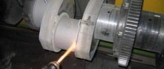
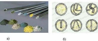
The essence of the cold gas-dynamic spraying method is to apply and fix on the surface of a product or part solid particles of metal or a mixture of materials ranging in size from 0.01 to 50 microns, accelerated to the required speed in air, nitrogen or helium. This material is called powder. These are particles of aluminum, tin, nickel, babbitts of various brands, a mixture of aluminum powder and zinc. The medium used to move the material can be cold or heated to a temperature not exceeding 700 °C.
Upon contact with the surface of the product, a transformation of the plastic type occurs, and the energy of the kinematic type transforms into adhesive and thermal energy, which contributes to the production of a durable surface layer of the metal. The powder can be applied not only to metal surfaces, but also to those made of concrete, glass, ceramics, and stone, which significantly expands the scope of application of the method of creating surfaces with special properties.
Depending on the pressure, the following types of cold gas-dynamic spraying are distinguished:
- high;
- low.
In the first case, helium and nitrogen are used as a working medium that moves powder material ranging in size from 5 to 50 microns. Metal particles, if they move, have a pressure of more than 15 atm. In the second case, compressed air is used, which is supplied under a pressure not exceeding 10 atm. These types also differ in such indicators as heating power and working fluid consumption.
The spraying stages are as follows:
- preparing the surface of the product for spraying using a mechanical or abrasive method;
- heating the working medium (air, nitrogen, helium) to the temperature established in the technological process;
- supplying heated gas to the equipment nozzle along with powder under the required pressure.
As a result, the powder is accelerated in the flow to supersonic speeds and collides with the surface of the part or product. A layer of metal is sprayed with a thickness, the thickness of which depends on the heating temperature of the supplied gas and pressure.
The surface of the product is prepared using an abrasive method using the equipment itself for applying gas-dynamic spraying by simply changing the mode parameters.
The scope of application of this type of spraying is quite extensive. Using the method, they seal leaks in containers and pipelines, repair parts and castings made of light alloys, apply electrically conductive, anti-corrosion and anti-friction coatings, eliminate mechanical damage, and restore seats in bearings.
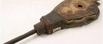
Cold gas dynamic spraying "BURATINO"
Popular message!
Hello, my name is Alexey. So I created another technology for myself. The idea had been around for a long time, having gained some knowledge on the internet, I got to work. In general, this is what I got. I don’t know what to call the beginning. I'll start with the largest detail. Case, metal 1mm.
Edge bend I bend the edges of the body for rigidity.
I folded the body parts for fitting.
I cut out the holes for the feeders and tried again.
I made a handle for the heating block. The handle is made of automotive putty.
I made a feeder a little earlier. Subsequently, after testing on the original powder, the internal structure had to be redone. What works on coarse powder works very poorly on fine powder. In general, I found the optimal design that works on both factions. The control unit is experimental, I always break the electronics into separate blocks and only after testing, combine them into one whole board.
Almost finished product)) Sandblasted and left outside, light rain and... I had to sandblast it again.
Next comes painting, gluing, assembly, adjustment. As a result, we have a finished, working product.
I apologize for the lack of photos of the insides of the feeder and heating block. Let me hide the design of these elements. In the manufacture of these blocks, I had to rack my brains, especially with the manufacture of the ceramic heater.
And finally, a video of this device working
Competitive work No. 29 , Technical category of the Welding Competition “Do It Yourself”
I smoke, drink, and spray.
Popular message!
Today I played with “Pinocchio”))) I sprayed copper onto an aluminum plate and tried soldering. mmmm, it solders, it holds.
Video of this soldering. I don’t know why the screen is blank, but there is a video there.
Movie of how I soldered the radiator.
And of course the autopsy.
I smoke, drink, and spray.
To be or not to be, that is the question. Is it worthy
I smoke, drink, and spray.
So so so. The next craft should be a miniature garage nuclear power plant. Moreover, from materials from a landfill. I think you should succeed.
Today I played with "Pinocchio"))) I sprayed copper onto an aluminum plate and tried soldering
Handsome. Keep it up, cool device.
Post edited by and21104: 13 August 2015 09:27
What is the point of such a publication? Yes, just to amuse your vanity. Show that “I’m so smart and cool. I did it, but I won’t tell others how.”
If the project is commercial, then let the person earn money from it, and not brag to people who are far from it.
I believe that in forums such as this, posts should be open, that have usefulness and repeatability by other people, fully revealing the design. Otherwise, it is useless information that no one needs. Therefore, such designs should not participate in the competition.
Therefore, such designs should not participate in the competition.
weldstar, before the commercial stage there are stages preceding it.
What is the point of such a publication? Yes, just to amuse your vanity. Show that “I’m so smart and cool. I did it, but I won’t tell others how.”
If the project is commercial, then let the person earn money from it, and not brag to people who are far from it.
I believe that in forums such as this, posts should be open, that have usefulness and repeatability by other people, fully revealing the design. Otherwise, it is useless information that no one needs. Therefore, such designs should not participate in the competition.
In general, all branded companies, which include both of the above, from the documentation provide only multi-page nonsense about how you should not stick your fingers into a socket, so as not to kill you, and about how to insert the electrode into the electrode holder. But they don’t give any diagrams or descriptions of the work.
Even brands don’t provide such information, but everything he does is according to the rules of the competition.
Western Yakutia call any time 89142527650 hash tag #ykt_master
I join in the congratulations, well done.
What is the point of such a publication? Yes, just to amuse your vanity. Show that “I’m so smart and cool. I did it, but I won’t tell others how.”
If the project is commercial, then let the person earn money from it, and not brag to people who are far from it.
I believe that in forums such as this, posts should be open, that have usefulness and repeatability by other people, fully revealing the design. Otherwise, it is useless information that no one needs. Therefore, such designs should not participate in the competition.
Looks like someone was “offended.” I don't see such a problem. HE SUFFERED THIS device and why should he explain something to anyone? Ivanovich, don’t pay attention to envious people. When I was young, I assembled radio-electronic devices, I can imagine how many things need to be provided for. Thanks again for posting.
Post edited by and21104: 13 August 2015 19:07
1. What is the point of such a publication?
2. Just to please your vanity. Show that “I’m so smart and cool. I did it, but I won’t tell others how.”
3. If the project is commercial, then let the person earn money from it, and not brag to people who are far from it.
4. I believe that in forums such as this, posts should be open, which have usefulness and repeatability by other people, fully revealing the design. Otherwise, it is useless information that no one needs. Therefore, such designs should not participate in the competition.
The main advantages of the method
The advantages of the technology include:
- performing work under any climatic conditions (pressure, temperature, humidity);
- the possibility of using stationary and portable equipment, which in the latter case allows for work to be carried out at the location;
- possibility of applying coating to local areas (defective areas);
- the ability to create layers with different properties;
- the ability to create a layer of the required thickness or different thicknesses in multilayer coatings;
- the process does not affect the structure of the product being sprayed, which is an important advantage;
- safety;
- environmental friendliness.
The disadvantage of this type of spraying is only one fact. The layers can be applied to ductile metals such as copper, zinc, aluminum, nickel and alloys based on them.
Manufacturers from different countries produce stationary and portable equipment for manual and automated application of coatings of varying productivity on different metals.
Principle of action, pros and cons of CGN
CGN has two main differences from the gas-thermal method of restoration. Firstly, spraying of a protective or restorative coating occurs at a low temperature not exceeding 150 °C, which in turn does not cause stress in the parts being processed and their deformation. Secondly, “cold” technology allows you to create a layer of adjustable thickness and within precisely specified boundaries. We’ll talk about other pros and cons a little later, but for now about the authors of the method and how it works.
Its developer is the Obninsk Powder Coating Center (Russia). The equipment they produce is called DYMET® . It is certified according to the GOST R system and is protected by patents from Russia, the USA, Canada and other countries. The technology is based on the principle of supersonic impact of tiny particles of fusible and other materials on the surface being treated. These are mainly polymers or alloys of carbides with metals with a particle size of 0.01-0.5 microns. Mixing with gas, they are supplied to the product at a speed of 500-1000 m/s.
Depending on the composition of the consumable material (powder) and changes in its application modes, you can obtain a homogeneous or composite coating with a solid or porous structure and its own functional purpose. This can be: restoration of the geometry of the product, strengthening and protecting the metal from corrosion, increasing the thermal and electrical conductivity of the material, as well as the formation of a wear-resistant coating that can withstand exposure to chemically active environments, high thermal loads, etc.
By the way, Obninsk engineers have already developed several modifications of DYMET® installations. Considering the wide demand for this equipment, both manual and automated cold gas dynamic spraying devices are now being mass-produced, which allows them to be used in industry, the oil and gas industry, as well as in small businesses for processing small parts. Moreover, there is nothing particularly complicated in the technology itself. To operate the complex (in addition to the spraying material), you only need compressed air (supplied at a pressure of 0.6-1.0 MPa and a flow rate of 0.3-0.4 m3/min.) and a 220 V power supply. Now about the advantages and disadvantages of the method. Firstly, unlike the gas-thermal method, CGN can be effectively used at normal pressure, in any temperature range and humidity level. Secondly, it is absolutely environmentally safe. Thirdly, due to its high speed, it can also be used for abrasive cleaning of surfaces. Well, the only drawback of the technology is the ability to apply coatings only from relatively ductile metals, such as copper, aluminum, zinc, nickel, etc.
Equipment used
The apparatus for gas-dynamic metal spraying consists of the following main parts:
- powder containers;
- working fluid supply systems, including a compressed gas cylinder and all the necessary components for it;
- nozzles (as a rule, there are several of them, they are of different configurations and are used for different spraying modes);
- control panel.
In the Russian Federation, high-quality equipment for spraying using the gas-dynamic method is produced by the powder spraying center in Obninsk under the trademark “DIMET”.
It meets the requirements of domestic GOSTs, is certified and protected by patents in many countries, including Russia. The process of repairing a part using gas dynamic spraying is shown in the video:
We ask those who have worked with different types of gas-dynamic spraying equipment and different metals and types of powders to share their experience in the comments to the text and tell us how the surface was prepared and the spraying process itself.
Claim
1. A portable device for gas-dynamic spraying of coatings from powder materials, containing a spraying unit including a compressed gas electric heater and a supersonic nozzle rigidly connected to the output of the electric heater and containing an input unit for powder material into the nozzle, a control unit connected to the compressed gas electric heater by a flexible pipeline and an electric cable , a powder feeder, the output of which is connected by a flexible pipeline to a unit for introducing powder material into the nozzle, characterized in that the compressed gas electric heater includes a casing in which a metal casing is placed with a gap filled with a heat insulator, inside which a fuel-generating element is installed, while in The metal body has holes that allow unheated gas to blow through the casing from the inside; the unit for introducing powder material into the nozzle is designed to ensure that powder material enters the supercritical part of the supersonic nozzle at an angle to its axis.
2. The device according to claim 1, characterized in that the compressed gas electric heater includes elements for monitoring and controlling its operating mode.
3. The device according to claim 2, characterized in that a pneumatic relay is used as an element for monitoring and controlling the operating mode, which ensures that the compressed gas electric heater is turned off when the gas pressure drops below the permissible level.
4. The device according to claim 3, characterized in that a triac is used as an element for monitoring and controlling the operating mode, which turns off the compressed gas electric heater when the pneumatic relay opens.
5. The device according to claim 2, characterized in that a temperature sensor installed at the outlet of the compressed gas electric heater is used as an element for monitoring and controlling the operating mode.
6. The device according to claim 5, characterized in that the temperature sensor cable is laid through the side wall of the housing of the compressed gas electric heater and is located under the casing of the compressed gas electric heater.
7. The device according to claim 2, characterized in that a manual valve for supplying compressed gas to the electric heater is used as an element for monitoring and controlling the operating mode.
8. The device according to claim 2, characterized in that a button for remote activation of the powder feeder is used as an element for monitoring and controlling the operating mode.
9. The device according to claim 2, characterized in that a handle with a button for remote activation of the powder feeder is used as an element for monitoring and controlling the operating mode.
10. The device according to claim 2, characterized in that a handle with a button for remotely turning on the powder feeder and a button for remotely turning on the supply of compressed gas to the compressed gas electric heater is used as an element for monitoring and controlling the operating mode.
11. The device according to claim 1, characterized in that the pipeline connecting the output of the powder feeder to the unit for introducing powder into the supersonic nozzle is located under the casing of the compressed gas electric heater.
12. The device according to claim 1, characterized in that the supersonic nozzle is located coaxially with the compressed gas electric heater.
13. The device according to claim 1, characterized in that the supersonic nozzle is located at an angle to the axis of the compressed gas electric heater.
14. The device according to claim 1, characterized in that the supersonic nozzle is made with a circular cross-section.
15. The device according to claim 1, characterized in that the supersonic nozzle is made with a rectangular cross-section.
16. The device according to claim 1, characterized in that the supersonic nozzle is made with a circular inlet cross-section and an outlet cross-section close to rectangular.
17. The device according to claim 1, characterized in that the unit for introducing powder material into the supersonic nozzle is made in the form of a fitting and a hole in the side wall of the supersonic nozzle.
18. The device according to claim 17, characterized in that the hole in the side wall of the supersonic nozzle is made at an angle to the nozzle axis other than 90°.
19. The device according to claim 1, characterized in that the unit for introducing powder material into the supersonic nozzle is made in the form of a pipeline passing through the critical section of the supersonic nozzle.
20. The device according to claim 1, characterized in that the ratio of the length of the supersonic part of the supersonic nozzle to the minimum transverse size of the nozzle ranges from 20 to 100.
21. The device according to claim 1, characterized in that the ratio of the cross-sectional area of the supersonic nozzle at the point where the powder material is introduced into the nozzle to the cross-sectional area of the critical section of the supersonic nozzle is not less than (1+0.8)P, where P is pressure gas at the nozzle inlet, MPa.
22. The device according to claim 1, characterized in that at least part of the supersonic interval of the nozzle is made in the form of one or more sections having a cross-section that is constant along its length.
23. The device according to claim 22, characterized in that the sections of the supersonic interval of the nozzle, which have a constant cross-section along the length, have a cylindrical cross-section.
24. The device according to claim 1, characterized in that the supersonic nozzle includes replaceable elements located approximately from the point where the powder material is introduced into the nozzle to the exit from the nozzle.
25. The device according to claim 24, characterized in that the replaceable elements are made of two L-shaped plates folded together, forming a cross-section of the nozzle close to rectangular.
26. The device according to claim 24, characterized in that the replaceable elements are made of metal.
27. The device according to claim 24, characterized in that the replaceable elements are made of ceramics.
28. The device according to claim 1, characterized in that the control unit includes a device for controlling the pressure of the compressed gas supplied to the compressed gas electric heater.
29. The device according to claim 1, characterized in that the control unit includes a device for stabilizing the temperature of the compressed gas supplied from the compressed gas electric heater to the supersonic nozzle.
30. The device according to claim 1, characterized in that the control unit includes a device for controlling the temperature of the compressed gas supplied from the compressed gas electric heater to the supersonic nozzle.
31. The device according to claim 1, characterized in that the control unit is connected to the powder feeder and includes a device for controlling the rate of supply of powder material from the powder feeder.
32. The device according to claim 1, characterized in that the control unit includes an electromagnetic valve for supplying compressed gas to the compressed gas electric heater.
33. The device according to claim 1, characterized in that the powder feeder is designed to be independently located.
34. The device according to claim 1, characterized in that the powder feeder is non-sealed.
35. The device according to claim 1, characterized in that the powder feeder includes two or more separate modules and a switch that provides supply of powder material from one of these modules to a pipeline connected to the unit for introducing powder material into the nozzle.
36. The device according to claim 35, characterized in that the switch ensuring the supply of powder material from one of the modules is integrated into the control unit.
37. The device according to claim 1, characterized in that it is equipped with load-bearing elements intended for temporary or permanent placement of all or some components of the device.
38. The device according to claim 37, characterized in that it is equipped with a carrying handle.
39. The device according to claim 37, characterized in that it is equipped with wheels for easy movement.