Metal arc surfacing technology
General information about surfacing
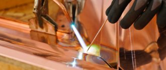
Surfacing involves applying molten metal to a melted metal surface with its subsequent crystallization to create a layer with specified properties and geometric parameters. Surfacing is used to restore worn parts, as well as in the manufacture of new parts in order to obtain surface layers with increased hardness, wear resistance, heat resistance, acid resistance or other properties. It allows you to significantly increase the service life of parts and significantly reduce the consumption of scarce materials in their manufacture. With most surfacing methods, as with welding, a movable weld pool is formed. In the head part of the bath, the base metal is melted and mixed with the electrode metal, and in the tail part the melt crystallizes and weld metal is formed. It is possible to deposit layers of metal both identical in composition, structure and properties with the metal of the part, and significantly different from them. The deposited metal is selected taking into account operational requirements and weldability. Surfacing can be carried out on flat, cylindrical, conical, spherical and other surface shapes in one or several layers. The thickness of the surfacing layer can vary over a wide range - from fractions of a millimeter to centimeters. When surfacing surface layers with specified properties, as a rule, the chemical composition of the deposited metal differs significantly from the chemical composition of the base metal. Therefore, when surfacing, a number of technological requirements must be met. First of all, such a requirement is the minimum dilution of the directional layer with the base metal that is melted when applying the beads. Therefore, in the surfacing process it is necessary to obtain a deposited layer with minimal penetration of the base metal, since otherwise the share of the base metal in the formation of the deposited layer increases. This results in unnecessary dilution of the weld metal with the molten base metal. Further, during surfacing, it is necessary to ensure a minimum heat-affected zone and minimum stresses and deformations. This requirement is met by reducing the penetration depth by adjusting the mode parameters, heat input, increasing the electrode extension, using a wide electrode strip and other technological methods.
The technology of surfacing various surfaces provides a number of methods for applying the deposited layer: thread beads with overlapping one another by 0.3 - 0.4 of their width, wide beads obtained due to electrode oscillations transverse to the direction of the bead axis, electrode tapes, etc. The location of the beads with taking into account their mutual overlap, it is characterized by the deposition step (Fig. 1).
B, hn, hpr - respectively, the width of the roller, a - along the generatrix, b - along the circumference. c - height of surfacing, depth of penetration, Sн - pitch of surfacing along the helix.
Surfacing of curved surfaces of bodies of revolution is carried out in three ways (Fig. 2): surfacing of beads along the generatrix of a body of rotation, along circles and along a helix.
B, hn, hpr - respectively, the width of the bead, a - along the generatrix, b - along the circumference, c - the height of the surfacing, the depth of penetration, Sn - the pitch of the surfacing along the helical line.
Surfacing along the generatrix is performed with separate rollers in the same way as when surfacing flat surfaces. Surfacing along circles is also carried out with separate beads until the initial and final sections are completely closed, offset by a certain step along the generatrix. With helical surfacing, the part rotates continuously, while the heat source moves along the axis of the body at a speed at which one revolution of the part corresponds to a displacement of the heat source equal to the deposition step. When surfacing bodies of rotation, it is necessary to take into account the possibility of molten metal flowing down in the direction of rotation of the part. In this case, it is advisable to shift the heating source in the direction opposite to the direction of rotation, taking into account the length of the weld pool and the diameter of the product (Fig. 3).
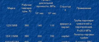
The choice of technological conditions for surfacing is made based on the characteristics of the material of the part to be deposited. Surfacing of parts made of low-carbon and low-alloy steels is usually carried out under conditions without heating the products. Surfacing of medium- and high-carbon, alloy and high-alloy steels is often performed with preheating, as well as subsequent heat treatment to relieve internal stresses. Often heat treatment (annealing) is performed after surfacing to reduce hardness before subsequent mechanical treatment of the layer. To perform surfacing, arc and electroslag welding methods are mainly used. When choosing the most rational method and technology of surfacing, one should take into account the operating conditions of the deposited layer and the economic efficiency of the process.
Surfacing methods and technology
Submerged arc surfacing.
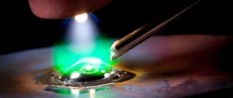
Heating and melting of the metal, as in welding, is carried out by the heat of the arc burning between the consumable electrode and the base metal under a layer of flux. Submerged surfacing is one of the main types of mechanized surfacing. The main advantages are continuity and high productivity of the process, minor losses of electrode metal, and the absence of open arc radiation. A distinctive feature of submerged arc surfacing is the good appearance of the deposited layer (smooth surface and smooth transition from one deposited bead to another). During the surfacing process, four main methods of alloying the deposited metal are possible (Fig. 4).
1. Use of alloy wire or tape and conventional fused fluxes. For surfacing, alloyed welding wires, special surfacing wires and alloyed strips, including sintered ones, are used. Surfacing is carried out using fluxes AN-20, AN-26, etc., which are selected depending on the composition of the electrode metal.
2. Use of flux-cored wire or flux-cored tape and conventional fused fluxes. The cored wire or tape is melted in the arc and forms a homogeneous liquid melt. This method makes it possible to obtain deposited metal with a total content of alloying impurities of up to 40 - 50%. The grade of flux-cored wire or strip is selected depending on the required type of deposited metal and its required hardness.
3. The use of conventional low-carbon wire or tape and alloying deposited fluxes (ceramic). This method allows you to introduce up to 35% of alloying impurities into the deposited metal. When surfacing, the most widely used ceramic fluxes are ANK-18 and ANK-19, which ensure good formation of the deposited metal, easy separation of the slag crust, and high resistance of the deposited metal against the formation of pores and cracks.
4. The use of ordinary low-carbon wire or tape and ordinary fused fluxes with preliminary placement of alloying materials on the surface of the welded product. Here, preliminary filling or dosed supply of alloying powders is possible, as well as preliminary laying of rods or strips of alloy steel, spreading of special pastes on the welding site, etc. In all cases, the applied alloying material is melted by an arc and goes into the deposited metal.
Due to the fact that there is much in common in the technology between surfacing and welding, the same equipment is used for surfacing as for welding using the corresponding methods.
Surfacing of carbon and low-alloy steels is carried out using fused fluxes OSTS-45, AN-348-A. AN-60 flux is suitable for single- and multi-electrode surfacing of low-carbon and low-alloy steels at normal and high speeds, as well as for surfacing with electrode strips.
Surfacing of alloy steels is carried out using low-silicon fused fluxes AN-22, AN-26, etc., and high-alloy chromium-nickel steels and other types of steels with easily oxidized elements (titanium, aluminum) are surfacing using fluoride fluxes ANF-1 and ANF-5.
To prevent the formation of slag inclusions and lack of penetration in the deposited layer during multilayer surfacing, it is necessary to carefully remove the slag crust from the previous layers.
Arc surfacing in protective gases.
Surfacing in shielding gases is used in cases where flux supply and removal of slag crust are impossible or difficult. The advantages of this type of surfacing are visual observation of the process and the possibility of its extensive mechanization and automation using serial welding equipment. It is used for surfacing parts in various spatial positions, internal surfaces, deep holes, small parts and complex shapes, etc. The technology of surfacing in shielding gases is in many ways similar to the technology of submerged surfacing, the only difference is that gas protection of the welding zone is used instead of flux. In addition to the listed advantages, this frees the welder from the need to add flux and remove slag. In order to reduce metal spatter, surfacing in shielding gas is carried out with the shortest arc possible. To avoid warping of parts, surfacing of flat surfaces is carried out in separate sections “randomly”. Cylindrical parts can be deposited along a helical line either with a continuous bead or with transverse vibrations of the electrode: Short sections can be deposited with longitudinal beads along the axis of the cylindrical part, but deformations may occur here, which must be balanced during the surfacing process. To do this, surfacing of each subsequent bead must be done on the opposite side to the one already deposited. When surfacing internal cylindrical and conical surfaces, special elongated nozzles are used.
Surfacing can be carried out in carbon dioxide, argon, helium and nitrogen. High-alloy steels, as well as aluminum and magnesium based alloys, are fused in argon or helium. Surfacing of copper and some of its alloys can be carried out in nitrogen, which behaves neutrally towards it. When surfacing carbon and alloy steels, cheaper carbon dioxide is used. Surfacing can be done with both consumable and non-consumable electrodes. A non-consumable tungsten electrode is usually used for surfacing in argon and helium. Surfacing in carbon dioxide with a consumable electrode using direct current of reverse polarity has become most widespread. Considering that carbon dioxide oxidizes the molten metal, deoxidizers (manganese, silicon, etc.) must be introduced into the surfacing wire. When surfacing, both solid and flux-cored wire are used. For surfacing parts made of carbon and low-alloy steels in order to restore their dimensions, solid-section welding wires Sv-08GS, Sv-08G2S, Sv-12GS are used, as well as surfacing wires Np-40, Np-50, Np-30KhGSA, etc. If necessary, obtain flux-cored wires are used to create a deposited layer with special properties.
The disadvantage of this method is that during surfacing in carbon dioxide there is a strong splashing of liquid metal, leading to the adhesion of splashes to the mouthpiece and clogging of the burner nozzle. In addition, the possibility of the gas jet being blown away by the wind makes surfacing in the open air difficult.
Arc surfacing with flux-cored wires.
Surfacing with flux-cored wire with internal protection is based on introducing into the wire core, in addition to alloying components, also slag-forming and gas-forming materials. The use of flux and gas protection when surfacing with such wire is not required. The alloying elements of the flux-cored wire pass into the seam, and gas- and slag-forming materials protect the metal from nitrogen and atmospheric oxygen. In the arc, a thin film of molten slag covers the droplets of liquid metal and insulates them from the air. The decomposition of gas-forming materials creates a flow of protective gas. After solidification, a thin slag crust forms on the surface of the weld bead, which may not be removed when applying subsequent layers. When surfacing, various self-protecting flux-cored wires are used. For surfacing low-carbon layers, welding wires such as PP-AN3 and others are used. To obtain layers with special properties, special wires are used. Thus, for surfacing parts operating at high pressures and elevated temperatures, PP-3ХВ3Ф-О flux-cored wire is used; surfacing of parts subject to intense abrasive wear is carried out with self-shielding flux-cored wire PP-У15Х12М-О (the letter O in the designation of the grade of flux-cored wire indicates that this flux-cored wire is intended for open-arc surfacing).
The technology for surfacing with self-shielding flux-cored wire is basically no different from the technology for surfacing in carbon dioxide. An open arc makes it possible to accurately guide the electrode and observe the process of formation of the deposited layer, which is of great importance when surfacing parts of complex shapes. One of the advantages of this method is the use of less complex equipment compared to the equipment used for submerged surfacing and shielding gas, as well as the ability to perform surfacing work in the open air; productivity increases compared to submerged arc surfacing and shielding gases, and the cost of the deposited metal decreases.
Plasma surfacing and sputtering.
The essence of this method is that the heating of the filler metal and the base metal is carried out by a compressed arc or gas plasma, isolated or coinciding with the arc column. The mechanism of formation of the deposited layer is the same as with other arc surfacing methods. Wire, rods and powders are used as surfacing materials for plasma surfacing. A diagram of plasma surfacing with powder injection into an arc is shown in Fig. 5. An arc is excited between the tungsten electrode 1 and the internal nozzle 2. The plasma-forming gas, passing through it, creates an indirect plasma jet 3, which ensures the melting of the filler powder.
Another arc, 4 direct action, burning between the electrode 1 and the base metal 5, coincides with the direct plasma jet. The latter creates the necessary heating of the surface, ensuring the fusion of the powder and the base metal. By changing the current value of a compressed direct arc, it is possible to achieve a minimum amount of penetration of the base metal. The thickness of the deposited layer can be changed within 0.3 - 10 mm with dilution with the base metal from 3 to 30%. In plasma surfacing with filler wire, an indirect arc burns between the tungsten electrode and the nozzle, and a direct arc burns between the tungsten electrode and the filler wire. The base metal also receives heat from these arcs. By changing the current strength, the share of the base metal and the surfacing productivity are adjusted. In this case, the welded product is not included in the welding chain.
Among the shielding gases used for plasma surfacing are argon, nitrogen, carbon dioxide, mixtures of argon with helium or nitrogen, etc. The choice of shielding gas is related to the degree of its effect on the deposited and base metals. Argon, helium, carbon dioxide, air, etc. can be used as a plasma-forming agent. To ensure stable operation of the surfacing process, it is necessary to use non-consumable electrodes made of a material that can withstand heating to high temperatures without destruction. These requirements are best met by electrodes made of pure tungsten or with additives of thorium dioxide, lanthanum and yttrium oxides. The advantages of this type of surfacing are a small depth of penetration of the base metal, the possibility of surfacing thin layers, high quality and smooth surface of the deposited metal.
In addition to surfacing, plasma heating can also be used for deposition of surface layers. The spraying process differs from surfacing in a number of ways. Sputtering is the process of applying metal layers of particles of sprayed material, heated to a melting temperature or close to melting, onto the unmelted surface of the workpiece. When spraying, filler material is used in the form of wire or powders fed into a compressed arc, where it is heated by a gas stream and supplied to the surface of the product at high speed. The thickness of the sprayed layer can vary from hundredths to tenths of a millimeter. Spraying of thicker layers is usually not carried out due to the fact that thick layers are prone to peeling off from the surface of the part (spalling). Sputtering can be done with metals and alloys, as well as with various types of compounds - oxides, carbides, nitrides, etc.
Technologically, in contrast to surfacing, sputtering is performed using the method of indirect heating by a separated arc plasma. If during surfacing the distance from the burner nozzle to the product is 6 - 25 mm, then during spraying it is 50 - 120 mm or more. Sprayed layers have a lower density and greater porosity compared to deposited ones and are more prone to chipping from the surface of the part if the technology is violated. However, they have virtually no dilution with the base metal.
Electroslag surfacing.
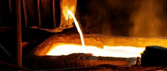
In electroslag surfacing, a slag bath, heated by an electric current passing through it, is used to melt the base and filler metal. This surfacing method is usually combined with the forced formation of a deposited layer. The essence of the electroslag surfacing process (Fig. 6) is that in the space formed by the surface of the welded product 1 and the forming crystallizer 4, cooled by water, a bath of molten slag 3 is created, into which electrode wire 5 is fed.
The current passing between the electrode and the product heats the slag bath to a temperature above 2000°C, as a result of which the electrode and base metals are melted, forming a metal bath, upon solidification of which a deposited layer 2 is formed.
To carry out the process of electroslag surfacing of various surfaces, a sufficiently deep slag bath is required, which is easiest to obtain with a vertical or inclined arrangement of parts. Compared to arc surfacing, this is a less universal method, but it is very effective in cases where it is necessary to deposit a layer of metal of large thickness (more than 14 - 16 mm) onto a part. Thanks to the use of high current and large cross-section electrodes, high productivity can be achieved - up to 150 kg of deposited metal per hour.
Vibro-arc surfacing.
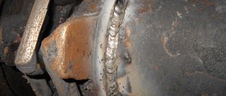
This method is usually used for surfacing parts such as rotating bodies with a diameter of 8 - 10 mm or more. The essence of this surfacing method is that the base and electrode metal is heated to melting by the heat that is released as a result of the occurrence of periodically repeating electrical discharges, i.e. intermittently burning electric arc; The deposited layer is formed during the crystallization of the molten base and electrode metal (Fig. 7). The short duration and intermittency of the electric arc is caused by vibrations of the electrode wire, which are created using electromagnetic or mechanical vibrators. During the vibration process, short circuits are observed due to the electrode wire touching the welded product (base metal), and when the wire is torn off, a large current is generated and an electric arc lights up. With an average current value of Id = 150 A, the extra current reaches 1000 A.
Surfacing wires (one or more) are used as filler metal, which can have reciprocating movements across the weld pool, as well as electrode strips, plates or rods of large cross-section, and sometimes pipes, which are used for surfacing cylindrical surfaces. When surfacing, fluxes AN-8, AN-22, etc. are usually used.
The arc burning duration is 0.002 - 0.003 s.
The surfacing installation consists of a vibrating arc head, control equipment, a rotator, and a current source. During surfacing, the following movements are performed: rotation of the welded part, translational movement of the vibrating arc head along the longitudinal axis of the welded part, feeding of wire into the arc zone and vibration of the wire. Power is supplied from rectifiers, welding generators, as well as from low-voltage transformers with a secondary voltage of 12 - 16 V or more. Higher performance is achieved when surfacing with direct current of reverse polarity. Typically, the welding circuit includes inductance, the value of which is selected depending on the vibration frequency of the electrode wire, voltage, type of current and other factors. Welding wires with a diameter of 0.8 - 2.0 mm are suitable for surfacing. In order to protect the molten metal from interaction with the environment, surfacing is carried out in streams of liquids or protective gases, as well as under a layer of flux. Aqueous solutions of soda ash are used; mixtures of soda ash, soap and glycerin; glycerol emulsions.
The intermittency of the process makes it possible to obtain a heat-affected zone of small width, therefore the deposited parts have very small deformations, which is especially important when surfacing complex products manufactured with high precision.
If surfacing is performed in a stream of liquid, accelerated cooling of the deposited metal occurs, so it has increased hardness and wear resistance. Vibrating arc surfacing is effective if it is necessary to deposit layers of metal of small thickness.
The disadvantages of vibration-arc surfacing are the relatively low deposition coefficient and low deposition productivity.
Surface preparation for surfacing
Before surfacing, the surface is thoroughly cleaned of oil, paint, scale and other contaminants. Surface defects, including the previously hardened layer, are removed mechanically or with a surface oxygen cutting torch. In order to reduce welding stresses, it is necessary to achieve a uniform thickness of the deposited layer. A surface that has uneven excavation with large fluctuations in height is leveled mechanically using metal-cutting equipment.
When preparing surfaces with local wear for surfacing, smooth transitions of the deposited metal to the base metal should be avoided (Fig. 18.1).
Rice. 18.1. Correct (P) and incorrect (N) preparation of surfaces for surfacing; 1…6 - sequence of roller application
Surfacing of flat and shaped surfaces is carried out using separate rollers (Fig. 18.2, a...d) or using the shuttle method (Fig. 18.2, e). When surfacing with separate beads, each of them is applied over the entire length at a distance from each other equal to 1/3 of the width of the bead. After cleaning the applied rollers from slag, fill the gaps between them (see Fig. 18.2, b, d). Other methods of surfacing with rollers are also used, for example, as shown in Fig. 18.2, a, - with an overlap of 1/3 of the width of the roller after cleaning the previous roller from slag.
Shuttle method
used for surfacing surfaces with a width of 40...80 mm. The peculiarity of the method is that the slag on the previous roller does not have time to harden, and therefore there is no need to remove slag from the previous roller.
Surfacing of bodies of revolution is carried out in one of three ways - along generatrices, along circles and along a helical line.
Surfacing along generatrices
(Fig. 18.3, a) are carried out with separate rollers in the same way as flat surfaces in the lower position, periodically turning the welded product.
Surfacing around circles
(Fig. 18.3,6) are also performed with separate rollers. The next roller is applied after clearing the previous one of slag with an overlap of ≈1/3 of the width of the roller.
Surfacing along a helix line
(Fig. 18.3, c) are carried out continuously, and cleaning of the previous roller from slag can be done with spring-loaded cutters.