How to disassemble an angle grinder yourself
Disassembling an angle grinder does not require any special metalworking skills; it does not cause serious difficulties. However, the work must be done very carefully and not with the utmost care. How, you will read on the Internet. Some sites show videos detailing the process. It is necessary to disassemble the angle grinder, not only when the oil has failed and there is no need to replace any part, this must be done to clean the tool from dirt.
If the grinder
, first of all, you should disassemble it and clean it thoroughly, for the most part the tool begins to work.
For this reason, the steps that are necessary to disassemble an angle grinder should be known to anyone who owns such a tool and does not want it to work poorly for a long time. The stores offer a large assortment of this mechanism, manufactured by controversial companies. They differ:
However, models from any manufacturer have the same technological assembly. Our client remains
grinders are equipped with the same set of parts.
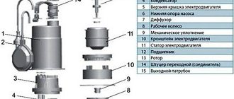
Main modules used
- Housing, usually made of special impact-resistant plastic.
- Powerful electric motor.
- High quality gearbox.
- .
- Electric motor switch.
- SJS system. The presence of an accounting system allows the tool to work smoothly without jumps. Already today, like oil, it turns off the grinder if the disk jams, reducing vibration as much as possible. How oil saves the operator from serious injury.
- Protective cover.
- Additional handle. With its help you can keep the grinder doing the job. This handle can of course be installed in different positions, which gives the tool versatility.
What may be required for work
The process of disassembling an angle grinder requires several tools:
- spanners;
- screwdrivers;
- pliers;
- vice;
- hammer;
- lubricant;
- rags;
- gas key.
The difficulty stems from the fact that the parts are in very close contact. This allows you to cope with the highest loads. Parts do not move operation A professional will do this disassembly much more reliably, but of course try it yourself with maximum care.
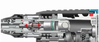
Angler anchor device
The armature of the angle grinder motor consists of a conductive winding and a magnetic circuit into which the rotation shaft is pressed. It has a drive gear at one end and a commutator with lamellas at the other. The magnetic core consists of grooves and soft plates coated with varnish to insulate them from each other.
Grinder anchor diagram
Two conductors of the armature winding are laid in the grooves according to a special pattern. Each conductor makes up half a turn, the ends of which are connected in pairs on lamellas. The beginning of the first turn and the end of the last are in the same groove, so they are closed to one lamella.
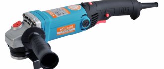
Construction and purpose of the grinder
The grinder is designed for grinding and cutting various materials.
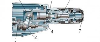
Basic elements of an angle grinder
The grinder consists of the following elements:
- The flat aluminum alloy gear housing allows for better heat dissipation.
- Carbon brushes.
- Handle attachment.
- Electronic soft start system. Prevents jerking when turning on and reduces starting loads on the engine.
- Quick-release protective cover.
- Ball bearings.
- Electric motor.
- Grinder switch.
Offers a large selection of bearing products - https://termopolis.com.ua/
How to check the angle grinder's anchor for serviceability
Types of armature faults:
- An insulation breakdown to ground is a short circuit of the winding to the metal rotor body. Occurs due to the destruction of insulation.
- Wiring of collector terminals.
- Uneven wear of the commutator.
- visually;
- multimeter;
- light bulb;
- special devices.
If the armature is faulty, the motor overheats, the winding insulation melts, and the turns become short-circuited. The contacts connecting the armature winding to the collector plates are unsoldered. The current supply stops and the motor stops working.
Types of armature diagnostics:
Standard diagnostics
Before taking the diagnostic device, inspect the anchor. It may be damaged. If the wiring is melted, the burnt insulating varnish will leave black marks or a specific smell. You may see bent or crumpled coils or conductive particles, such as solder residue. These particles cause short circuits between turns. The lamellas have curved edges, called cockerels, to connect to the winding.
Due to disruption of these contacts, the lamellas burn out.
Other commutator damage: raised, worn or burnt plates. Graphite from the brushes may accumulate between the lamellas, which also indicates a short circuit.
Bent commutator plates
How to check with a multimeter
- Set the resistance to 200 ohms. Connect the probes of the device with two adjacent lamellas. If the resistance is the same between all adjacent plates, then the winding is working. If the resistance is less than 1 ohm and very close to zero, there is a short circuit between the turns. If the resistance is two or more times higher than average, then there is a break in the winding turns. Sometimes when there is a break, the resistance is so great that the device goes off scale. On an analog multimeter, the arrow will go all the way to the right. But digital won’t show anything.
Diagnosis of the armature winding with a multimeter
Video: how the check is carried out
If you don't have a tester, use a 12-volt light bulb with up to 40 watts.
How to check the rotor of an angle grinder using a light bulb
- Take two wires and connect them to the lamp.
- Make a break on the negative wire.
- Apply voltage to the wires. Place the ends of the break against the collector plates and rotate it. If the light bulb lights up without changing brightness, then there is no short circuit.
- Perform a short circuit test to the iron. Connect one wire to the lamellas and the other to the rotor iron. Then with the shaft. If the light is on, it means there is a ground fault. The winding closes to the rotor housing or shaft.
This procedure is similar to diagnostics with a multimeter.
Need a repair tool
To repair a Bosch grinder, do not do without a tool. Give a warning right away if you have a screwdriver, this will greatly speed up the process of disassembling and assembling the tool.
But you can do this with a screwdriver set, preferably one with a ratcheting mechanism. You can't do without an open-end wrench, which you use to unscrew the nut that secures the drive screw gear.
It is better to have a special puller for removing bearings.
Electrical diagnostics can be performed using a tester or short circuit detection device.
This is especially useful because it allows you to determine whether the rotor or stator is faulty without removing the assembly.
The Bosch grinder diagram will help you do the repair yourself, and these instructions will help you adequately deal with any problem.
Checking with a short-circuited turns indicator (SCI)
There are anchors where the wires connected to the collector are not visible due to being filled with an opaque compound or due to a bandage. Therefore, it is difficult to determine the commutation on the commutator relative to the slots. An indicator of short-circuited turns will help with this.
This device is small in size and easy to use.
First check the anchor for breaks. Otherwise, the indicator will not be able to detect a short circuit. To do this, use a tester to measure the resistance between two adjacent lamellas. If the resistance is at least twice the average, then there is a break. If there is no break, proceed to the next step.
The resistance regulator allows you to select the sensitivity of the device. It has two lights: red and green. Adjust the regulator so that the red light starts to light. On the indicator body there are two sensors in the form of white dots located at a distance of 3 centimeters from each other. Attach the indicator with the sensors to the winding. Rotate the anchor slowly. If the red light comes on, it means there is a short circuit.
Video: IKZ at work
Diagnostics with an armature testing device (throttle)
The armature testing device determines the presence of an interturn short circuit in the winding. The inductor is a transformer that has only a primary winding and a magnetic gap cut out in the core.
Anchor testing device diagram
When we place the rotor in this gap, its winding begins to act as the secondary winding of a transformer. Turn on the device and place a metal plate, such as a metal ruler or hacksaw blade, on the anchor. If there is an interturn short circuit, the plate will vibrate or be magnetized towards the armature body due to local oversaturation of iron. Rotate the armature around the axis, moving the plate so that it lies on different turns. If there is no short circuit, the plate will move freely along the rotor.
Anchor testing device
Video: How to make a throttle with your own hands and check the anchor
Disassemble your Bosch sander
The owner of a power tool needs knowledge of his device and the ability to disassemble it.
Knowing how to disassemble a grinder allows you to perform tasks such as changing the oil, replacing bearings and carbon brushes.
Disconnect the gearbox housing pos. 821 from the stator housing pos. 888, it is necessary to disassemble (remove) the body of the handle of the grinding machine, pos. 24.
This operation must be performed to remove the carbon brushes pos. 810 that hold the rotary commutator.
At the second stage, unscrew 4 (four) screws pos. 61, which fix the gearbox housing and stator.
After pulling out the rotor along with the gearbox, begin disassembling the gearbox.
Repair of a Bosch grinding machine begins with disassembling the gearbox, pos. 821. Disassembling the gearbox begins with unscrewing 4 (four) screws pos. 60. Typically, the screws are screwed into the sealant at the factory. It will take some effort.
READ Guide Rail for Bosch Circular Saw
Just take note! For low power Bosch grinders, spindles are used in the gearbox. For grinders with a power of more than 1000 W, helical gears are used in the gearboxes.
How to remove a driven gear
By removing the gearbox cover, you can obtain a helical gearbox, pos. 26.
To remove the gear you will need to use a press or puller. But using a stripper is difficult, as it requires the use of special thin sponges.
Before removing the helical gear, check the gear backlash, tooth integrity, contact point.
The reference position 50 is pressed against the spindle shaft, pos. 26. If the bearing has a large gap, it is noisy when turning, the oil has dried out, it is advisable to replace it.
To remove the bearing, remove the gear, tighten the ring and remove the bearing. If the bearing remains in the gear housing during removal of the rotor shaft assembly, the bearing is removed using a hammer and a soft point.
How to remove the drive mechanism of a Bosch grinder
Gear drive pos. 27 is removed from the rotor shaft in the following sequence:
- Take the rotor by the hand and open it with a wrench pos. 45 counterclockwise;
- Remove washer pos. 59.;
- Remove the gear screw, key 27.
Visually check the integrity of the gear teeth and contact points.
If the gears are very worn (licked) or have jagged teeth, they need to be replaced. And gear replacement is always done in pairs.
Bosch low-power shredders use a needle bearing as a support bearing in the gearbox.
Repair bosch usm yourself, strictly follow the instructions. If you need to remove a needle bearing from its housing, quick thinking is a must. It can be disassembled only when destroyed.
To get a destroyed race, you can use a proven method.
A valve with a diameter slightly larger than the inner diameter of the destroyed needle bearing cage. The valve is secured in the screwdriver chuck and carefully screwed into the clamp at low speed. When the valve reaches the bottom of the gear housing, it will begin to lift the clamp.
In addition to the spindle shaft needle bearing, Bosch grinders also use two bearings mounted on the rotor shaft.
How to remove bearings from a Bosch grinder rotor
Remove the bearings from the rotor position. 803 Bosch sharpener, it is recommended to use pullers.
Bearing pos. 15 next to the collector can be easily removed, but to remove bearing pos. 14 from the impeller this is complicated by the fact that a number of preparatory operations are required.
Bearing pos. 15 is closed with a soft rubber bushing. This rubber protective pos. 33 also covers the bearing pos. 14.
To disassemble the bearing pos. 14, unscrew the nut pos. 45, remove the gearbox pos. 17 and plastic protection pos. 33. Using a puller, you can easily remove the bearing from the rotor shaft.
What if there is no stripper? A vice, two metal straps and a hammer with a soft metal extension will help.
Disassembling a Bosch sander
How to repair an anchor at home
A third of screwdriver failures occur due to the anchor. With everyday intensive operation, malfunctions can occur within the first six months, for example, if the brushes are not replaced in a timely manner. With gentle use, the screwdriver will last a year or more.
The anchor can be saved if the balance is not disturbed. If during operation of the device you hear an intermittent hum and there is strong vibration, then this is an imbalance. This anchor must be replaced. And the winding and commutator can be repaired. Small short circuits are eliminated. If a significant part of the winding is damaged, it can be rewound. Worn and badly damaged lamellas should be sharpened, extended or soldered. In addition, you should not undertake anchor repairs if you are unsure of your capabilities. It is better to replace it or take it to a workshop.
Collector groove
Over time, wear from the brushes forms on the commutator. To get rid of it, you need to:
- Grind the commutator using cutters for longitudinal grinding, that is, through cutters.
Passing straight cutter
Don't forget to clear the rotor of chips to prevent a short circuit.
Video on the topic
How to rewind an anchor
Before disassembling the armature, write down or sketch the direction of the winding. It can be left or right. To determine it correctly, look at the end of the armature from the commutator side. Wear gloves and take sharp wire cutters or a hacksaw. Remove the winding end parts. The collector needs to be cleaned, but it is not necessary to remove it. Carefully, without damaging the slot insulators, knock out the rods of the remaining parts of the winding using a hammer and metal chisel.
How to Remove a Gear from a Grinder Anchor
Check and repair the grinding machine armature yourself
As Shakespeare said: Nothing lasts forever under the moon. Home appliances, while seemingly annoying, are no exception. It happens that the most powerful mechanism burns out. There is no need to prepare for the meeting. This is an ordinary rumor. A fact without panic, with a strong belief that there are no hopeless situations. How does a grinding machine work, common malfunctions, how to check the armature of an electric motor, find the cause of the breakdown and not remove the task? Knowledge of the structure of the main components of a power tool will allow a home foreman to make a diagnosis and not repair the angle grinder.
How to rewind an anchor step by step instructions
If the balance of the reinforcement is not disturbed, and the problem lies solely in the warped windings, then such reinforcement can be returned without the help of others by rewinding the coils. Rewinding a rotor at home requires a lot of patience and care.
The master must have the ability to work with a soldering iron and devices for diagnosing electronic circuits. If you are not confident in your own abilities, it is better to take the engine to a workshop for repairs or change the entire armature without the help of others.
To rewind the anchor without the help of others, you will need:
- Wire for new winding. A copper conductor is used with a diameter that exactly matches the old conductor;
- Dielectric paper to insulate the winding from the core;
- Varnish for casting coils;
- Soldering iron with tin-lead solder and rosin.
Before rewinding, it is important to count the number of turns of wire in the winding and wind the same amount of new conductor onto the coils.
The rewinding process consists of the following steps:
- Dismantling old windings. They must be carefully removed without damaging the iron body of the fittings. If any burrs or damage are found on the body, they must be smoothed with ratfil or puttied with emery. From time to time, in order to completely cleanse the body of toxins, masters prefer to burn it with a torch.
- Preparing the collector for connecting a new wire. There is no need to remove the manifold. You need to examine the lamellas and measure the contact resistance relative to the body with a megometer or multimeter. It should be less than 0.25 MOhm.
- Removing the old wiring on the manifold. Carefully remove the remaining wires, cut grooves in the contact part. In the future, the ends of the coil wires will be inserted into the grooves.
- Installation of anchor sleeves. The sleeves are made of dielectric material 0.3 mm wide, for example electronic cardboard. Cut out a certain number of sleeves and stick them into the grooves of the cleaned anchor.
- Winding coils. The end of the new conductor is soldered to the end of the lamella and is wound in alternating radial movements counterclockwise. This is called a correct conclusion. Winding Repeat for all coils. At the collector, stretch the wires with a thick thread of cotton fabric (it is forbidden to use nylon, as it melts when heated).
- Checking the winding. At the end of the laying of all windings, check with a multimeter that there are no short circuit interruptions and possible interruptions.
- Final healing. Treat the finished coil with varnish or epoxy to hold the winding together. At the factory, impregnations are dried in special ovens. At home, this can be done in the oven. Alternatively, use fast-drying varnishes for impregnation, applying the coating in several layers.
Detailed photo report on replacing the armature bearings of an angle grinder (grinder) one thousand four hundred W 220V.
The angle grinder received its nickname “ Bulgarian ” back in the days of the Soviet Union. Since at that time this instrument was made and supplied from Bulgaria. A grinding machine in the arsenal of home tools is a more versatile and functional assistant. The grinding machine is subjected to heavy and uneven loads and long periods of operation, which is why malfunctions occur more often than with other power tools.
When turned on, my grinder began to produce a strange sound and excessive vibration. It is more expensive to operate a tool with such features.
We begin repairing the grinding machine by unscrewing the four screws of the box cover.
Using a screwdriver, remove the cover of the box with the secondary shaft and gearbox. The output shaft bearing turned out to be in good condition, without free play or jamming.
But the front reinforcement bearing completely fell apart. The bearing balls were in gear grease and had a small circlip on one side. To replace the front bearing, first unscrew the caps of the contact brushes of the fittings and remove the brushes.
Then we unscrew the four screws securing the grinding machine box to the stator, and remove the fittings together with the box body.
To remove and install the gear retaining ring, you need to make a regular tool. For this I used old scissors. The ends of the scissors were sanded, as in the photo.
This is the view that my containing ring has. To make it easier to attach the retaining ring when installing the gearbox, the ends of the scissors were heated with a hot gas burner and bent at right angles to the plane of the scissors. Then it is heated and cooled again in machine oil.
After dismantling the valve gearbox, I removed the valve from the box body. This is a type of front bearing reinforcement.
The outer cage of the reinforcing bearing is removed from the box body by lightly pressing an iron screwdriver inserted into the groove of the cage on the inside of the box body. It is important not to distort the cell when pressing.
But the internal race of the bearing sat tightly on the reinforcement shaft.
To remove it I used a standard threaded screw holder.
The studs were unscrewed from it to rotate when threading. And the rod holder itself is installed on the bearing race so that the screws for fastening the rod fit into the groove of the bearing race. Then tighten the screws moderately on each side and thus firmly attach the holder to the holder. Now we grab the puller with the paws of the tool holder and remove the clamp from the shaft.
READ What types of circles are there for grinders?
This is what the front armature bearing on my sander had.
New bearings must be filled with oil. To do this, you will need a sharp awl, Litol 20 four grease and a mandrel for attaching the bearing caps. To lubricate the closed bearing, you need to remove the cover by nailing it with an awl, as in the photo.
Now fill the bearing with oil and put the cover in place.
To place the cap in the bearing without damage, it is necessary to select a mandrel with a diameter slightly larger than the outer diameter of the bearing cap. I used a wrench head.
The bearings are lubricated. Press the front bearing into the box body using the outer ring of the old bearing and secure it with a flange.
At the anchor, the armature commutator is cleaned with P1000 sandpaper. Using a utility knife, carefully, without much pressure, clean the paths between the lamellas of the collector. And after these operations, we carefully wipe the collector with a cotton cloth moistened with white spirit or another solvent.
Next, you need to press the reinforcement shaft into the inner race of the front bearing. To do this, place the box body on a wooden surface with the bearing facing up. We insert the reinforcement shaft into the bearing cage from above and slightly touch the mandrel, along the rear reinforcement bearing we put the reinforcement in place.
We place the gearbox on the valve shaft. If, after installing the gear, the groove for the ring extends beyond the end of the gear, then the installation is correct. We put the containing ring in place.
If the groove extends through the end of the gear or is halfway through, the shaft must still be installed in the housing.
After these operations, remove the old rear bearing from the valve shaft and install a new one. We place the armature with the box into the stator and tighten the four screws that secure the box. Check the shaft for rotation. The shaft should simply spin and not get stuck in the bearings. We put the contact brushes in place and screw on their caps. Now we put a special oil substance for angle grinders into the grinder box and replace the box cover with the output shaft.
We tighten the four mounting screws and check the grinder by turning it off.
The chopper should rapidly gain speed and operate without any extraneous overtones. At this point, the repair of the grinding machine can be considered complete. Success for you in your work!
Replacing bearings on an angle grinder. Replacing the anchor yourself at home
Practice indicates that if a decision is made to change the fittings of a grinding machine, then it is better to change it together with the support bearings and the motor cooling impeller.
The substitution will require:
- New LBM anchor. Must match your model. Substitution with other models is prohibited.
- Screwdrivers, wrenches.
- A soft brush and cloth for cleaning the mechanism.
Repair: Elimination of insulation breakdown
If the insulation breakdown was small and you found it, you need to clean the area of carbon deposits and check the resistance. If its value is normal, insulate the wires with asbestos. Apply quick-drying “Super Moment” type glue on top. It will seep through the asbestos and insulate the wire well.
If you still haven’t found the location of the insulation breakdown, then try carefully soaking the winding with impregnating electrical insulating varnish. Punched and unpierced insulation will be saturated with this varnish and become stronger. Dry the anchor in a gas oven at about 150 degrees. If this does not help, try rewinding the winding or changing the armature.
Soldering the collector plates
The slats are mounted on a plastic base. They can be erased to the very base. Only the edges remain that the brushes cannot reach.
Such a collector can be restored by soldering.
- Cut the required number of lamellas to size from a copper pipe or plate.
- After you have stripped the armature of copper residues, solder it with regular tin and soldering acid.
- When all the lamellas are soldered, sand and polish. If you don't have a lathe, use a drill or screwdriver. Insert the armature shaft into the chuck. First, sand with a file. Then polish with grit sandpaper. Don't forget to clean the grooves between the slats and measure the resistance.
- There are lamellas that are not completely damaged. To restore them, more thorough preparation is necessary. Lightly grind the commutator to clean the plates.
Damaged commutator plate
Expanding the space with a drill
Preparing the lamella in the groove
If the collector has been completely worn out, then after soldering it will last no more than a month of active use. And plates that are not completely damaged after such repairs can withstand several replacements of brushes and do not become desoldered.
Galvanic extension of collector plates
Reduced copper is very hard. The service life of the collector is like new. Galvanic extension can be used to restore both a completely worn out collector and partially damaged plates.
Main malfunctions, their causes and diagnostics
Main breakdowns and prerequisites:
- Burns, sparks and jerking. Prerequisites: violation of the insulation of the armature winding, wear of the brushes, commutator, clogging of the brush holders. Even after changing the brushes, the sander sparks and jerks if the brush holders are clogged.
- Popping sound. Brushes or closing the rotation of any of the windings.
- Crunchy sound. Cause. Bearings.
- Mechanical rumble and strong tapping. Box malfunction.
- The grinder did not work and would not turn on. If the disc rotates manually or does not rotate, the reason is in the box. If it turns easily, check the electronic circuits. If the chains work, check the motor and brushes.
- The spindle lock button is broken. The prerequisite is to press it when the disk is spinning or the disk is stuck.
Brushes
Brushes should be inspected from time to time. When you get one to 40%, change both. Also clean the brush holders.
- To remove the brushes, you must either pull out the rear housing or remove the plugs in the housing.
- Clean the brush holders from dust and carbon. Wrap a cloth around the screwdriver and moisten it with alcohol. Carbon deposits are cleaned with ratfil. The brush should just move in the brush holder, then it will be perfectly pressed by the spring.
- Insert new brushes.
How to disassemble and assemble an angle grinder
To eliminate defects, the grinding machine must be disassembled.
- Pull out the nut that holds the drive disk.
Unscrew the bolts securing the protective cover.
Unscrew the bolts of the grinder housing and those that secure the housing to the gearbox.
Remove the upper part of the rear housing. Unscrew the bolts securing the cord. Remove the wires and button from the grooves. In some models, for example, in DWT, the rear housing is not disassembled into parts, but is completely removable.
Unscrew the box bolts located around the housing mount.
To remove the fittings from the duralumin body, unscrew the nut located in the box body.
Reassemble the instrument in reverse order.
Spindle lock button
If the button falls out, you will not be able to work with such a grinder.
Spindle lock button
Since the spindle can spontaneously lower onto the gearbox and fix it during operation.
Locking spindle
The locking block consists of a spindle with a rubber ring, a spring and a plastic button.
- Disassemble the gearbox to change the button.
- Pull the spindle out of the housing.
- Place the spring on the button from the inside.
- Insert the spindle into the gear housing from the inside and the button from the outside. Press until it clicks.
- Assemble the gearbox.
How to ring the start button. Cleaning brush holders. Anchor repair
If the balance is not balanced, the fittings need to be changed. The winding and commutator must be repaired. Small short circuits are eliminated. If a significant part of the winding is damaged, it can be rewound.
A not very lean collector is corrected by a groove. But if the plates are worn out in the plastic base or partially burn out, then restoration is carried out by soldering or galvanic build-up.
Very warped manifold
If the collector was completely worn out, then after soldering it will last no more than a month of active use. And the plates that are not one hundred percent damaged after such repairs can withstand several replacements of brushes and are not soldered. You will need to cut the copper strips to size and solder them with a huge amount of solder. File the excess and grind.
Reduced copper is very hard when electroplated. The life of collectors is like new.
100% restored collector
Galvanic build-up can be used to restore both completely worn-out collectors and partially warped plates. The restored collector must be deepened and the slabs. Cut with a drill or a hacksaw knife.
In order to rewind the anchor , you need to correctly disassemble it and remove the characteristics of the template:
- Winding direction.
- How many grooves and lamellas.
- Number of conductors in the groove.
- The winding pitch, in other words, how many grooves are located between the grooves of one section. For example, if the conductors leave the first gap and enter the sixth, then step = 5.
- How many conductors fit into one groove, how many coils are in one section.
- Wire thickness.
For example, eighty conductors per connector, twelve strips and 20 four sockets. Twelve sections of two coils. Winding takes place in two circles, so we divide the eighty conductors in the groove by 2, and another 2, since there are two coils. We get 20 turns of one coil.
Armature winding diagram
- We solder the beginning of the wire to lamella one and pass it through the first and sixth grooves. We make 20 turns. The 1st coil of the first section is ready.
- We solder the wire onto two lamellas and repeat the winding through the same grooves. The 2nd coil of the first section is ready.
- Solder the wire to lamellas 3. Pass the coil through the second and seventh grooves. We wind the first coil of the 2nd section and stuff the wire onto the lamellas 4.
- Let's fix the second coil of the 2nd section on the lamellas 5.
- We continue this path until the end of the wire reaches lamella 1
How to remove the old winding and wind the new winding:
To remove the ends of the winding, use iron dust or wire cutters.
Carefully, without damaging the insulator grooves, knock out the rods of other winding parts using a hammer and an iron chisel.
Use the file to remove any remaining impregnation. Count the conductors in the groove and determine the diameter of the wire. Draw a diagram. Cut out the insulating sleeves from the cardboard and stick them into the grooves.
After winding, weld the section leading to the collector plates. Check the winding with a tester.
Saturate the winding with epoxy.
MrPodshipnik
Bearing replacement, repair
Enter the marking or size (for example: 8*22*7) of the product and the country of sale
- Car brands
- Auto components
- Moto
- Velo
- Equipment
- Tool
- Technique
New instructions
- How to make your own repairs and replace the bearing on the steering column in a ZOOM bicycle 10/09/2019
- How to independently, at home, replace a bearing in an electric motor of a Philips food processor 10/05/2019
- We repair a DAB heating circulation pump and change the bearing ourselves 10/04/2019
- How to repair a Shimano fishing reel yourself and replace a faulty bearing 10/03/2019
- We replace the bearing and repair the SBR_ 132_A concrete mixer ourselves 10/02/2019
Replacing an angle grinder bearing at home
From this article you can learn how to replace the bearing of an angle grinder yourself.
A very common household tool is an angle grinder, technically correctly called an angle grinder. Sometimes breakdowns occur as a result of excessive load, or parts fail due to prolonged use.
- How to disassemble an angle grinder and replace the bearing yourself?
- What are the reasons why an angle grinder fails?
- Tools necessary for repairing and replacing defective parts
- How to disassemble an angle grinder and remove bearings. Step by step steps
- Assembling the tool with new parts
- Disassembling an angle grinder for prevention
- Video: DIY replacement of grinder bearings
- Photos on the topic
Design features of the Bosch angle grinder
A design feature of the Bosch grinder is represented in the use of a gearbox as a support bearing for the driven helical gear of a needle bearing. In Bosch rotary hammers, the driven gear is attached to the spindle shaft by pressing.
In low-power Bosch angle grinders, in which spur gears are installed in the gearboxes, the installation of shims is provided. This design allows you to restore the functionality of the gear contact by reducing the thickness of the gasket. At high tool speeds, helical gears wear out significantly less than spur gears.
The work environment for grinders is most often a dusty space. Dust is the main danger leading to failure of power tools, grinders and grinders.
What are the reasons why an angle grinder fails?
The grinder has a mechanism that bears the heaviest load - the rotor. It is also called an anchor. The damage it suffers is varied. These include temperature loads, electromagnetic, and, of course, mechanical problems.
As a result, do not be surprised that the angle grinder does not work precisely because the rotor is faulty. The armature winding overheats and burns out, this will cause a short circuit. So many owners of this tool often carry out all repair work themselves.
A worn commutator causes increased vibration in parts such as brushes. They burn, causing the mechanism to spark strongly. The main function of such brushes is to transmit current to the commutator.
The bearings in the rotor wear out very often. If you do not carry out timely diagnostics and prevention of bearings, they are completely destroyed. If during operation of the angle grinder you hear a noise that was not there before, be sure to check the condition of the bearings.
The stator is a stationary component in an electric motor; it contains a winding. The angle grinder very rarely breaks directly because of the stator.
The gearbox is responsible for rotating the gear. It needs to be cleaned and lubricated on time.
Most often, brushes are changed in a grinding machine, because the basis for their manufacture is graphite. Replacing these parts is not difficult.
The most common causes of grinder breakdowns
In order not to find yourself one on one when disassembling a tool with the question “I removed all the parts, but which one was acting up?”, you need to first identify what could be the cause of malfunctions of the device.
If the tool malfunctions, it may spark or jerk. This may be due to some insulation failures or wear and tear of other types of spare parts. This situation also happens when replacing brushes.
Sometimes customers complain about a loud popping sound when plugged in. This may indicate a short circuit.
If you hear a crunching sound when you turn it on, then the problem is in the tool bearings.
In rare cases, there is some tapping when pressing the on key. This indicates a gearbox malfunction.
Sometimes, the tool may not turn on at all. Then you need to make sure that the disk turns, if it turns, but it is tight, this indicates problems with the gearbox. If the disk scrolls without problems, then it is worth checking the main motor of the device or brush.
Provided that the tool gets very hot, you first need to understand which of its parts is hotter. If the area where the motor is located heats up, the reason is due to improper operation of the brushes. If heating occurs near the gearbox, then the cause is dried out lubricant.
If the angle grinder does not gain speed and speed when rotating, the reason is in the operation of the engine. In this case, it is recommended to check the serviceability of the control board.
Tools necessary for repairing and replacing defective parts
For high-quality and effective repair of an angle grinder, you will need the simplest tools that almost every thrifty owner has.
Having a screwdriver will make disassembling the angle grinder much easier. But, in its absence, you can easily get by with just different screwdrivers. It is desirable that they have a ratcheting mechanism.
To remove the nut that secures the drive helical gear, you will need a wrench called an open-end wrench.
To dismantle the bearing, you cannot do without a special puller.
Perform diagnostics of the electrical component of the device being repaired using a tester. There is also a special device that detects short circuit of turns. This device is very convenient, since you can diagnose a breakdown in the stator or rotor without having to remove the unit.
Be sure to have a diagram of the grinding machine. Knowing the location of the main components will greatly facilitate the disassembly of the mechanism, repair, or replacement of unusable parts.
A few words about lubrication of the Interskol grinder
Before assembling the mechanical components of the Interskol angle grinder, be sure to lubricate the parts with the recommended lubricant. Lubricants from foreign and Russian manufacturers are widely represented on the Russian lubricants market. Today you can purchase high-quality lubricants from domestic manufacturers. They are in no way inferior in quality to their foreign counterparts, but are several times cheaper.
A special lubricant with high adhesion has been developed for grinder gearboxes. Adhesion is the property of a substance to adhere to a lubricated surface.
Conclusions:
- When choosing an angle grinder, opt for a Russian angle grinder from Interskol;
- You will receive a reliable, durable, ergonomic, cheap tool;
- Give preference to Interskol grinders of the USHM 125 class;
- In the household they are more in demand and safer.
I wish you success!
How to disassemble an angle grinder and remove bearings. Step by step steps
After disassembling this device, you can replace broken bearings, re-lubricate all parts, dismantle damaged brushes and install new ones.
In order to separate the rotor and stator housings, it is necessary to first remove the handle housing in the machine. This is done so that it is possible to remove the carbon brushes. They hold the rotary manifold.
The second step is to unscrew the four screws that secure both housings - rotor and stator.
Take out the gearbox along with the starter and start disassembling it. There are also screws on the gearbox that need to be removed. There are four of them in total. This procedure will require some effort on your part, since the factory assembly involves the use of sealant.
Grinders of different models have different types of gears. In low-power models, spur gears are used. With a power of more than a thousand watts - the use of helical gears.
Once you remove the gear cover, you will be able to remove the assembly that houses the helical gear. To remove it, use a press or puller.
To do this, you will have to use special thin tubes. For this reason, it will be inconvenient to use the puller.
Before removing the gear, it is necessary to check the play in the gear connection. Also check that all teeth are intact. And the contact patch is checked.
If you have identified the following signs in a bearing that is located on the spindle shaft:
- when you scroll it, a characteristic noise is heard;
- noticed the appearance of backlash;
- no lubrication.
If all these signs are present, it is necessary to replace the old part with a new one. To do this, the bearing must be removed. How to do it?
First of all, remove the gear along with the retaining ring. After this, you can easily remove the worn element. When you remove the rotor shaft assembly, the bearing may remain in the gearbox, inside the housing. In this case, use a hammer with a soft tip on top.
To remove the drive gear in an angle grinder, do the following:
- clamp the rotor, unscrew the nut with an open-end wrench;
- the washer is removed;
- Now take out the gear itself.
After checking the appearance of the gear, decide whether this part needs to be replaced. Keep in mind that both gears need to be changed at the same time.
Low-power angle grinders are equipped with a needle bearing, which serves as a support bearing.
Dismantle this part only when it is completely destroyed. There is a proven way to remove a destroyed clip.
1.Choose a tap diameter larger than the inner diameter of the cage.
2.Place and secure it into the screwdriver chuck. Gradually, at low speeds, tighten it into the cage. When the tap hits the housing bottom in the gearbox, the cage will rise.
The rotor shaft has two more bearings, in addition to needle bearings. To remove them from the rotor, I would recommend using a puller.
The bearing attached to the manifold is fairly easy to remove. The impeller is also equipped with a bearing, which will take a little more time and skill to remove. Both bearings are covered for protection with special rubber caps.
To remove and replace these parts, the nuts are unscrewed, the spur gear is removed, as well as the plastic protection. You can now freely remove the bearing from the rotor shaft using a puller.
If you don't have a puller in your tool kit, there is one method, take note of it. Remove the bearing with a vice along with two metal strips and a hammer with a special metal attachment.
Basic electrical faults of the grinder Interskol
As a rule, the most common cause of failure of an angle grinder is an electrical fault. The main percentage of electrical failures of grinders is the failure of carbon brushes.
Repair of control circuits for angle grinders Interskol
The control circuits of grinders of different models are slightly different from each other. It all depends on the power of the tool and the availability of innovative developments. Some angle grinders have a built-in electronic unit that regulates the smooth start.
Wiring diagram of the control circuits of the angle grinder Interskol ushm 125
In Interskol angle grinders 125 angle grinders, electric brushes pos. 55 are mounted in special brush holders pos. 44, which can only be reached by removing the back cover pos. 51 of the stator housing pos. 42.
After removing the cover, you need to unscrew the screws pos. 50 holding the brush holder housing.
Brush wear is determined by their remaining length. The length of working carbon brushes cannot be less than 5 mm.
Power is supplied via cable pos. 53. At the points where the cable enters the angle grinder and into the plug pos. 53, the cable may break off. The malfunction can be resolved by replacing the entire power cord or the failed part. Twists are not allowed.
The power cable supplies voltage to the switch pos. 41, inserted into the housing at pos. 47. To control the switch button there is a lever pos. 46. When performing maintenance, clean the switch lever with silicone grease.
Wiring diagram of the control circuits of the angle grinder Interskol ushm 230
Power is supplied via cord pos. 50 to the switch pos. 46, to which the electronic unit pos. 40 and carbon brushes pos. 38 inserted into brush holders pos. 37 are connected. The electrical part of the angle grinder also includes a stator, pos. 32, and a rotor, pos. 27.
Replacing carbon brushes on angle grinders Interskol USHM 230 does not require removing the back cover. It is enough to unscrew the cap of the brush holder pos. 36 and pull out the brush holder with the carbon brush. But you can replace the switch, electronic unit, capacitor pos. 42 only by disassembling the rear handle pos. 44, 45. To do this, you need to unscrew four 4x16 screws, pos. 44.
How to repair the rotor of an angle grinder Interskol
Rotor failure occurs for the following reasons:
- The carbon brushes have worn out or are faulty;
- Short circuit or breakage of windings;
- The lamellas of the armature commutator have worked:
- The rotor bearings are damaged or jammed.
Rotor repair requires special knowledge, instruments and equipment. It is preferable to buy a new rotor or send it to a specialized service center for repairs. But remember, it costs money. For those especially gifted, we recommend rewinding the rotor with your own hands.
Use a puller to remove the bearings from the armature. But you can also use improvised means. For example, a vice, strips of metal, a hammer, a soft metal attachment.
Dismantling bearings from the armature ushm 125
There are two bearings installed on the rotor, pos. 31: the rear one, near the collector, pos. 32.
Bearing size 608Z.
And on the impeller side there is a bearing, pos. 28, size 6000-2 RS. Russian analogue 180100.
The bearings are removed after removing the rotor from the gearbox housing. To remove the rotor from the gearbox, you need to remove the bevel gear drive, position 26, sitting on the rotor shaft.
To do this, you need to unscrew the M8x3.5 nut, pos. 25, and remove the drive gear Z=12. It is fixed with a key pos. 30. The bearings are removed using a puller.
Dismantling bearings from the armature ushm 230
To remove the bearings from the armature, pos. 27, it is necessary to pull the rotor out of the gearbox housing, pos. 19. Unscrew the M8 nut pos. 20, remove the locking washer pos. 21, remove the drive gear pos. 22. gently rocking, pull the rotor out of the gearbox housing. The bearing will remain in the gear housing. It is closed by a bearing cover, pos. 25, which is attached to the gearbox housing with three M5x8 screws, pos. 26. A bearing of size 6201-2RS is installed in the gearbox housing. Russian analogue 180201.
On the collector side, bearing pos. 28 is removed using a puller. Bearing size 608RT. Russian analogue 180608.
Repair of the stator of the grinder Interskol
Repair of the stator of any angle grinder Interskol is carried out after determining the nature of the malfunction. Most often the stator burns out. This occurs due to overheating of the tool. A malfunction of the stator is indicated by involuntary uncontrolled spinning of the rotor of the angle grinder.
To repair the stator, it is necessary to remove it from the housing. The performance of the stator can be checked without removing it from the housing. But this can only be done in specialized workshops. Or if you have an IK-2 short-circuited turns monitoring device. It is possible to determine a break or short circuit in the stator windings without dismantling the stator. The burnt stator is removed, rewound, or a new one is installed instead.
You can rewind a burnt stator yourself.
The rewind algorithm is as follows:
- Cut the damaged winding from one edge in any way;
- You count the number of turns of the winding, determine the direction of its winding, the percentage of filling of the stator core groove, measure the diameter of the wire;
- After removing the burnt winding, clean the core grooves and check the insulation;
- Using the prepared wire, wind the required number of turns of the stator windings into the prepared grooves;
- Solder the ends of the windings, having first put an insulating wire on them;
- Impregnate the stator windings using alternating current;
- Clean traces of impregnation inside and outside the stator housing;
- Check the free movement of the rotor inside the stator.
DIY video of repairing the stator of an angle grinder Interskol
Video:
Assembling the tool with new parts
After disassembling the instrument and necessary replacement of all damaged parts, we will reassemble it. Make sure you have all the tools, lubricants, and clean rags on hand for finishing touches.
All previous grease must be removed and replaced with fresh grease. Use lubricants from trusted manufacturers, buy them in specialized stores.
First of all, you need to assemble the rotor. You need to press in the bearings and install the impeller. Before doing this, carefully lubricate the bearings. Using a wooden tool, press them onto the top of the shaft.
Cover the collector bearing with rubber protection. This is the same diagram of how to assemble a rotor shaft.
Next, we reassemble the gearbox. We begin this process by installing the gearbox on the rotor shaft housing. When the shaft is already inside the housing, place the drive gear on it, then the washer and fixing nut.
Now install the gear housing, together with the shaft located in it, inside the stator housing. It is necessary to press both housings after the commutator bearing is already in the seat. Next, check whether the rotor rotates easily on the bearings.
The final step is to place the lid back where it was. Check how the spindle shaft rotates. If you determine that the rotation is easy even with the movement of your hands, you can start tightening the screws. They secure the cover to the body. Before doing this, lubricate all screws using sealant.
What you might need for work
The process of disassembling a coffee grinder requires several tools:
- Spanners;
- Screwdriver;
- Pliers;
- Vise;
- Hammer;
- Oil;
- Rags;
- Gas key.
The difficulty of disassembling the grinding machine is due to the fact that the parts have very close contact. This allows you to cope with the highest loads. The parts do not move during operation, and oscillatory movements do not occur. Of course, the technician will do everything possible to disassemble it, but you can try to do everything yourself with extreme caution.
Tools required for work: round nose pliers, ruler, calipers, pliers, electric drill, steel brush, megger.
Before disassembling the coffee grinder, you need to prepare your work area by removing all unnecessary parts from the workbench. A clean table will ensure that you don't accidentally lose any parts.
At the first stage, the bolt holding the body is unscrewed. It is very easy to remove, there are no particularly tight seams. Then you need to unscrew the screw and remove the plastic plate. The outer cover should be positioned towards the cord.
Basically, all models of grinding machines have different devices. However, the common part is the electric motor, which includes:
- Anchor;
- Stator;
- Collector;
- Brush.
Another essential part of the shredder is the gearbox, which is designed to control power and speed. An electric motor is installed in the housing along with a gearbox.
Disassembling an angle grinder for prevention
I would recommend disassembling your sander not only for repairs and replacement of worn parts, but also for regular maintenance. This will significantly extend the operating time of the electrical device. Any mechanism works longer and better if it is properly cared for. The Bulgarian is no exception.
Disassemble the tool as described in this article. Only now you are doing this not for repairs, but in order to thoroughly clean and lubricate such a necessary tool in the household.
The most ideal option for cleaning is to use compressed air and a blower attachment in compressors. You will have to take into account that the angle grinder is cooled through the distance in the middle of the armature and stator.
Excessive amount of construction dust, various particles on the engine. All this needs to be cleaned from time to time.
And if you have already disassembled the angle grinder for prevention, apply fresh lubricant to the parts, as described earlier.
As you can see, maintaining and repairing an angle grinder is not such a difficult task!
How to remove an anchor from an angle grinder?
Often during operation, power tools become clogged with small mechanical debris. This can lead to overheating and malfunction of the device. To prevent such situations, it is recommended to periodically dismantle the tool to assess wear and clean it from contamination.
The chopper also needs regular maintenance checks. When sawing or grinding various hard materials with it, fine mechanical dust flies in different directions. It often hits the instrument directly. To clean the device, you will have to disassemble it, and you need to focus on the question of how to remove the armature from the grinder. Similar manipulations are also carried out during repair or replacement of any part of the instrument.
In a grinding machine, it is the armature that is most sensitive to natural wear. Overheating or regular operation may cause a short circuit in its contacts. You can also remove the armature from the grinder to check if it is working properly. In most cases, the rejected part is not suitable for further use. It is replaced with a new one. But how to disassemble it with a machine without breaking it, and how to remove the armature of the grinding machine? In this article, we will try to provide you with detailed information that will help you understand the ins and outs of the process.