- Oil stations with electromagnetic control
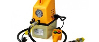
- Oil station NEE18-3I20T1
An oil station with a working pressure of 18 MPa and low flow rate is a profitable purchase for driving actuators that do not require high operating speeds. Despite the small size, the pressure created by the oil station is sufficient to drive presses, elevators, tippers and other equipment. Due to a carefully selected layout, the cost of the station was kept low, without sacrificing quality, thus, an oil station of this model will be an effective investment for the enterprise.
4.8 18 18
General technical characteristics:
- Pump displacement – 2.09 cm3
- Nominal pressure – 18 MPa
- Nominal flow – 3 l/min
- Oil tank volume – 20 l
- Drive motor power – 1.1 kW, 1500 rpm.
- Power supply – three-phase current, voltage 380 V, 50 Hz
- Weight (with dry tank) – 22 kg
- Dimensions – 450x370x410 mm
Price: 59930 rub. Order
The configuration, physical dimensions, pressure and flow values can be changed at the request of the customer. All hydraulic pumping stations undergo mandatory inspection and testing
Structural elements of oil stations
The design of hydraulic pumping stations includes:
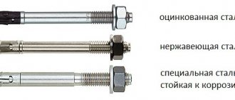
- Filler neck . It is equipped with a filter that prevents the tank from clogging with foreign objects when it is opened.
- Hydraulic tank , the capacity of which should be 25% greater than the volume of all channels of the serviced tool or equipment. Made from “black” or corrosion-resistant steel. Heavy-duty equipment uses tanks with additional internal baffles.
- Pump – vane, gear, plunger, radial or axial plunger. The range of speeds of movement of the working fluid is 3-300 l/min.
- Primary drive – electric, pneumatic, hydraulic, gasoline, diesel.
- Pipeline is a system of channels that ensures the flow of working fluid under pressure to the mechanisms of the equipment being serviced and its return to the tank. In areas experiencing strong vibration, flexible hoses are installed.
- Suction filter . Mounted at the outlet of the storage tank, it prevents solid inclusions contained in the working fluid from entering the hydraulic main. Only a filter element for rough cleaning is installed in this area.
- Hydraulic distributor . Designed to start, stop, and change the direction of the flow of working fluid. The distributors have manual, electromagnetic, pneumatic, and hydraulic control. Most often, spool-type hydraulic valves are installed. They are easy to use, small in size, and reliable.
- Level meter, thermometer, pressure gauge and other measuring devices.
Purpose of the oil station
Hydraulic oil station with electric drive type NEE18-3I20T1 is designed to create hydraulic energy and use it in a bench installation to test the functioning of steering racks. The oil station is made in climatic version “U” of placement categories 2, 3 according to GOST 15150-69. Ambient temperature from plus 5°C to plus 40°C. Working fluid: VMGZ TU 38 101479-86, MGE-10A OST 38 01281-82. The cleanliness class of the working fluid must be at least class 10 according to GOST 17216-71. The temperature of the working fluid during operation of the pumping unit should be in the range from plus 5°C to plus 50°C. The operating position of the pumping unit is horizontal. Tilt up to 5° in any direction is allowed.
How to connect a pumping station?
A ball valve is attached to the outlet of the unit using a fitting. They can draw water from any depth and even at a significant distance from the water source from the building.
When operating a submersible pump, you only need a pipe and a check valve - it already has a filter of this type. If a submersible well pump is used, only a check valve and a pipe are needed, and a coarse filter is already included in its design. We install a coarse filter made of propylene mesh at the lower outlet of the ejector.
Next comes the insertion of pipes into the installation site of the system. Provides a certain supply of water, depending on the capacity of the hydraulic tank, and its supply even when the power supply is turned off. Basic installation and connection diagrams When assembling a water supply system, various connection diagrams for pumping stations in a private house can be used. After the hydraulic accumulator reaches the required parameters, the tank is connected to the system and turned on. If you are just a meter short of being able to install conventional equipment, you can install the station in a well or above a well.
Installing a pumping station in a pavilion equipped on the street will protect you from the main disadvantage of this type of equipment - noise during operation. Having decided on the installation location of the pumping equipment station, we begin its installation. Without a plumbing system, it is impossible to fully live in a house around the clock.
Plastic pipelines are inserted through the straight elbow, which lead to the ejector unit; finally, the space between the pipelines and the inside of the elbow can be filled with polyurethane foam. The sewer pipe serves as a protective layer.
The pipeline is laid in the dug trench. Thereby stabilizing the pressure; The pumping system is equipped with a control unit to determine when it is necessary to turn the equipment on and off. We connect the pumping station to the well and pump in water
Force created by hydraulic cylinders of different diameters and extension time
| Hydraulic cylinder liner diameter (mm) | Extension time per 100 mm (sec) | Force (kg) |
| 30 | 1.4 | 1300 |
| 40 | 2.7 | 2300 |
| 50 | 4 | 3600 |
| 60 | 5.6 | 5200 |
| 70 | 7.5 | 7000 |
| 80 | 10 | 9200 |
| 90 | 13 | 1170 |
| 100 | 16 | 14400 |
Hydraulic diagram of the oil station
Designations
| Designation | Name | Quantity | Note |
| N | Pump | 1 | P = 21 MPa |
| M | Electric motor | 1 | N = 0.75 kW |
| KP | safety valve | 1 | |
| MN | Pressure gauge | 1 | |
| F1 | Suction filter | 1 | e = 90 µm |
| F2 | Drain filter | 1 | e = 25 µm |
| F3 | Filler breather filter | 1 | |
| R | Hydraulic distributor 4/3 | 1 | P = 21 MPa |
| B | Tank | 1 | V = 10 l |
| U | Level indicator | 1 |
Description of the hydraulic circuit:
The electric motor (M) rotates the pump (H). The working fluid is sucked by the pump from the tank (B) through a mesh filter (F1), a high-pressure hose is supplied to the working cavity of the product. The maximum pressure of the oil station is adjusted using a safety valve (KV). The maximum operating pressure of the oil station is 18 MPa. The hydraulic distributor (P) is designed to control the flow of hydraulic fluid. The hydraulic valve spool positions are switched by an electromagnet from the control box (working position “A” and idling “B”). Return to the neutral position (“0”) is carried out due to the action of an elastic element (spring). The pressure in the system is controlled by a pressure gauge (MP) (0...40 MPa). An oil filter (F2) is installed on the drain line. The pressure difference of the working fluid before and after the filters should not exceed 0.5 MPa. A pressure drop above the permissible level leads to their failure. The working fluid is poured into the tank through a filler strainer (FZ). The liquid level in the tank and its temperature are respectively controlled using a level gauge (U).
Do-it-yourself hydraulic station for the press
When working with industrial tools that require high pressure, you cannot do without using a hydraulic oil station. We will talk further about the design, advantages and features of making an oil station with your own hands.
Hydraulic oil station design
The oil station is used to convert various types of energy into mechanical fluid energy.
The hydraulic oil station pumps hydraulic fluid and creates pressure in the working area of the actuators.
The hydraulic oil station is characterized by the presence of:
- Hydraulic tank - it is made of black steel or stainless steel. The inner surface of the tank is sandblasted and double coated with polymer. If the oil station is expected to operate for a long time, then partitions are placed inside the tank to facilitate mixing and cooling of the liquid. The main functions of the hydraulic tank are:
- acting as a reservoir in which the oil is located;
- cooling of working fluid;
- function of a coarse filter in which contaminants settle;
- separation of water and oxygen from liquid;
- supply of working fluid for pumping equipment.
- Pump. Pumps come in different types and differ in technical features. The fluid supply rate of the pump ranges from 3 to 300 liters per minute. Here are the types of pumps that are used in hydraulic oil stations:
- gear type;
- plate type;
- radial plow type;
- axial piston type.
- The prime mover - in this case, hydraulic. Its main function is to convert mechanical energy into rotational force or kinetic energy.
- Pipeline, which is a system of channels consisting of high-pressure hoses. The pipeline also includes metal pipes, which are characterized by modular or butt installation. Their main function is to connect hydraulic equipment with regulators and energy distributors. Responsible for the transfer of working fluid and its timely return.
- Drain filter - it is responsible for cleaning the working fluid returning to the hydraulic tank device.
- A suction filter, which prevents solid parts of mechanical impurities from entering the pump line. This filter is installed directly on the pipe section under the working fluid. Since the pump has limited suction capabilities, the resistance of the filters on the way to the working fluid should be minimal. These filters perform rough cleaning of the liquid and consist of several structural parts. Some filters have a bypass valve or magnetic trap.
- The filler neck in which the air filter is located - this element serves to prevent dirt from entering the working fluid when opening the tank.
- Measuring elements: pressure gauge, oil quantity indicator.
- Distributors, which are:
- electrohydraulic;
- manual, with one or several sections.
Operating principle of a hydraulic oil station
A hydraulic oil station is also called a hydraulic drive, hydraulic unit or hydraulic pump station. It appears as a system that converts energy through the control of hydraulic fluid.
The type of converted energy directly depends on the design features of the primary engine, which is the main element of the oil station.
The operating principle of a hydraulic oil station is to transmit torque from the primary source of mechanical energy (electric motor or internal combustion engine) to the hydraulic pump shaft.
Using a suction filter, the working fluid, in this case oil, is sucked in using a hydraulic pump.
The fluid is then transferred through a pipeline system to hydraulic equipment, which distributes it and determines its pressure on the way to the hydraulic cylinder or hydraulic motor that does the work.
The spent working fluid travels through a pipe system, passing through drain filters, and returns to the hydraulic tank.
Advantages and scope of use of a hydraulic oil station
If we compare a hydraulic oil station with a standard compressor, it stands out with the following advantages:
- reducing the costs of transporting equipment, as well as installation, maintenance and connection of the oil station;
- compact dimensions facilitate transportation and operation of the device;
- low fuel consumption;
- high productivity and efficiency of device use;
- The oil station has lower noise production than the compressor;
- the device is characterized by a wide range of uses; it is possible to connect the oil station to units and equipment of various capacities and purposes;
- simplicity and ease of operation of the equipment does not require hiring and training of specialists.
The scope of use of hydraulic oil stations is mainly aimed at ensuring the functionality of hydraulic devices and tools.
Using a hydraulic oil station, it is possible to start almost any mechanism. Therefore, they have a fairly wide range of applications.
The hydraulic oil station is capable of operating:
- with static hydraulic tool;
- with electrical installation equipment;
- with a dynamic hydraulic tool;
- with equipment for construction or railway purposes;
- with slurry pumps;
- with drilling equipment;
- with injection molding machines;
- with presses;
- with systems that lift and move large and dimensional structural objects;
- with test stands;
- with technological equipment.
Hydraulic oil stations are used for pumping and purifying oil.
They are capable of supplying oil to individual parts of machinery, lubricating and cooling its elements.
Using a hydraulic oil station, hydraulic cylinders, machines, equipment and pipeline systems are tested.
The main areas of application of hydraulic oil stations:
- industrial;
- metallurgical;
- construction;
- energy;
- agricultural;
- transport.
Main types of hydraulic oil stations
Hydraulic oil stations are divided according to several parameters. Depending on the type of movement, they are:
- mobile type;
- stationary type;
- self-propelled type.
The first type is characterized by compact dimensions and is easy to transport. Mobile oil stations have low power and are used in the private sector.
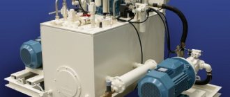
Stationary devices are used in industry. Such oil stations have large dimensions and operate at high power.
Self-propelled hydraulic oil stations combine the advantages of the two previous types. They have both high power and means of transportation, and in particular wheels.
Depending on the prime mover, the oil station is:
- hydraulic;
- electrical;
- pneumatic;
- gasoline;
- diesel
Oil stations based on a gasoline engine are the most compact.
To operate a pneumatic oil station, a compressor is required, the minimum operating pressure of which is 0.5 MPa.
Hydraulic oil stations based on a pneumatic drive are used in enterprises that have strict operational requirements, and in particular, in petrochemical or mining plants. Such oil stations have a longer service life and use devices that provide system lubrication by spraying the working fluid.
Depending on the type of distributors, hydraulic oil stations are:
- With the presence of a manual unloading crane - they pump and release pressure into the hydraulic cylinder device. Used when working with equipment that has a spring return, such as a pipe bender or nut cutter.
- An oil station with two-position distributors pumps up such pressure that it can not only supply oil for operation, but also ensure its return back to the system. Used for equipment that has a two-position action.
- Devices with a three-position distributor are the most popular. They allow you to work in the position of the working stroke - hold and return. Used to operate presses.
According to pressure, oil stations are:
- low pressure - up to 16 MPa;
- medium pressure - up to 45 MPa;
- high pressure oil station - up to 155 MPa;
- heavy-duty pressure - more than 155 MPa.
Hydraulic oil stations differ in the way they are controlled and are:
- manual type;
- electromagnetic type;
- automatic type.
In the first type of oil stations, the operation is controlled using a handle. The electromagnetic control method involves pressing a button station, which is located on the oil station, or using a remote control on the buttons.
The third type of control is a combination of the two previous methods. The operation can be controlled either with a remote control or with a handle.
Depending on the type of hydraulic drive, oil stations are:
- single-stage;
- two-stage.
Single-stage ones have a single-flow pump. Such stations allow you to regulate the speed and operating mode of the hydraulic cylinder.
Oil stations of this type are used in cases where it is necessary to apply equal forces to compress the pressed body. For example, when making briquettes from waste or garbage.
They are also used in the production of dry ice, gluing wood beams, pressing or pressing.
Two-stage oil stations consist of a two-stage cycle. They are distinguished by the presence of a dual pump and a bulkhead hydraulic panel. Such stations significantly save electricity.
Recommendations for choosing a hydraulic oil station
To buy a hydraulic oil station, you should contact specialized companies or directly to the manufacturers.
The price of an oil station depends on the following factors:
- type of prime mover;
- pressure;
- power;
- distributor type;
- possibility of movement;
- manufacturer.
When choosing an oil station, pay attention to the operating pressure of the drive, the working volume of the piston section, the speed and magnitude of the working stroke, the type of drive and the settings of the hydraulic oil station.
The main characteristics include:
- performance or rated power value;
- fuel tank size and working fluid pressure value.
Determining the type of oil station in accordance with the control method directly depends on the technical features of the enterprise or the direct functions of the oil station.
Please note that the useful volume of the fuel tank must be a quarter larger than the total working volume of the hydraulic equipment that will be used in conjunction with the oil station. At the same time, another function of the oil tank is lubrication and cooling, so if it is not larger than the required volume, these functions will not be performed.
To be able to operate multiple tools at the same time, you should purchase a multi-port valve, port, or multi-port pump.
When choosing a hydraulic oil station, pay attention to its technical features and first read the operating instructions to determine the recommended supply of working fluid and compare it with the tool. If the feed is less, there may be a risk of slow operation of the equipment; if the feed is larger, the equipment will fail.
Oil station equipment
- 1) Tank
- 2) Cover
- 4) Gear pump
- 5) Electric motor
- 6) Coupling with elastic element
- 7) Glass
 Four-line three-position hydraulic valve with electromagnetic control
- 9) Hydroblock
- 11) Safety valve
- 13) Pressure gauge
- 14) Pressure gauge stand
- 15) Filler neck with strainer and breather
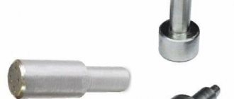
- 21) Suction filter
- 22) Drain filter
- 23) Oil level indicator combined with a thermometer
- 24) Cork
Design and principle of operation of the oil station
The hydraulic oil station NEE18-3I20T1 consists of a tank 1 equipped with a cover 2; pump group, consisting of a pump 4 (gear), an electric motor 5, connecting their coupling shafts with an elastic element 6 and a glass 7, which acts as a shell, a four-line three-position hydraulic valve with electromagnetic control 8 mounted on a hydraulic unit 9, a safety valve 11, a pressure gauge 13 , installed on the rack 14, filler neck 15 with a strainer and breather; suction filters 21 and drain 22; oil level indicator combined with a thermometer 23. Oil from the tank is drained through plug 24. Oil from tank 1 is pumped by pump 4, driven by engine 5 through coupling 6, through suction filter 21 and pipeline and then enters hydraulic distributor 8, which supplies oil to pressure to the working parts. From the hydraulic distributor, oil flows to the drain through a pipeline to drain filter 22 and again enters tank 1. Oil is poured into tank 1 through filler neck 15. Oil is drained through plug 24 installed in the wall of tank 1. The oil level is monitored using indicator 23. The maximum pressure developed by the oil station is adjusted by safety valve 11. The pressure setting in the system is controlled by pressure gauge 13.
This is not a public offer. All information provided is for reference only. Specifications, specifications and physical dimensions are subject to change without notice.
Connecting a station with a surface pump
In addition to hoses, plastic or metal-plastic pipes are also used. After the hydraulic accumulator reaches the required parameters, the tank is connected to the system and turned on.
You cannot run the pump dry; you need to pour water into the upper hole of the pumping station; this procedure must be performed once. The depth of the installation surface must be such that all equipment is below the freezing level.
This allows you to lay an extensive water supply network and connect household appliances to it - a shower cabin, a boiler, a dishwasher and a washing machine.
This method of installing a pumping station is good because if everything is done correctly, the system works without problems.
It may have more power, so we recommend that you provide such a station with its own power supply line. Main elements Pumping equipment should not be constantly running, since continuous operation can lead to rapid wear of the mechanisms and components of this device. They can pump air first and then water. If it is necessary to connect a boiler or home water heater to the system, the pressure must be sufficient. Trick with a water station in the house