Rewinding of armatures of electric motors of power tools
Correct operation of the Makita 2450 rotary hammer with a commutator motor is accompanied by slight sparking of the brushes in the commutator area.
A properly functioning electric motor has a uniform spark with a short tail. By changing the sparking pattern, you can determine the nature and location of the malfunction in the Makita 2450, 2470 hammer drill.
The reasons for the increase in sparking in the electric motor commutator may be faulty brushes and their wear, short circuit or armature breakage, malfunction of the stator windings of the electric motor, breakage or improper fastening of brush holders.
Significant sparking in the commutator area leads to the appearance of grooves on the commutator, burning of the plates, and uneven abrasion of the brushes.
The occurrence of the listed defects causes rapid wear and wear of the lamellas of the collector itself.
Roughness is higher than normal
Since a hammer drill is a powerful tool, small sparks are allowed without load; with significant effort on the tool, single sparks may run in a circle. In case of strong sparking, it is necessary to find out the reason for the strong sparking.
The most common fault on the commutator is the increasing roughness of the lamellas with increasing sparking of the brushes.
An increase in the surface roughness of the Makita 2450 rotary hammer commutator occurs not only due to increased sparking. Copper oxide forms on the copper plates of the commutator; its hardness exceeds the hardness of the carbon brushes. The amount of roughness is affected by uneven wear of brushes and carbon deposits from sparking.
Scratches are formed not only due to uneven wear of the brushes and different structure of the material, but also due to the entry of solid particles from the air into the working area.
Improper storage of a Makita rotary hammer can lead to the appearance of oxide on the copper plates of the collector due to high humidity or significant temperature changes during operation.
To eliminate defects on the surface of the collector, it must be sanded.
Causes of malfunction
The collector is a copper drum distributed into lamella sections. The end of the previous and the beginning of the next winding are connected to each of the lamellas, and the operating principle of the unit is based on changing the direction of the winding field. In this case, the causes of collector malfunction may be:
- Rough or worn commutator surface. It occurs during engine operation as a result of dust particles entering the device, the appearance of soot or oxide. This problem is eliminated by grinding the surface of the lamellas.
- Grooves. They are the result of contact between the brushes and are removed by grooving the commutator on a special machine.
- Protrusion insulation. This is a technical issue related to the abrasion of the copper plates and the protrusion of micanite. The problem can be eliminated by cultivating the collector.
- Beating. The commutator runout is associated with a malfunction of the bearings, or with uneven protrusion of the copper plates. The malfunction can be eliminated by grooving or replacing the bearings, depending on the identified cause.
How to properly sand the surface of the commutator
Before you begin to modify the manifold of the Makita 2470 rotary hammer, you must balance the rotor.
Option for measuring the runout of the commutator relative to the rotor
At home, grinding the manifold of a Makita 2450 or 2470 rotary hammer is best done with sandpaper attached to a wooden block already on a balanced rotor.
The end of the rotor shaft is secured in the drill chuck through soft copper or aluminum foil. A drill with a rotor is securely fastened in a vice or homemade device.
While rotating the rotor, try to center it in the drill chuck.
Installing the rotor into the chuck
The procedure for disassembling, repairing, and assembling a hammer drill rotor
Here is the sequence for repairing a rotor with a short circuit in the windings:
- Trimming the front part of the windings.
- Removing the collector and frontal parts and measuring the diameter of the wire being removed.
- Removal and cleaning of groove insulation, counting the number of turns along the sections.
- Selection of a new collector.
- Installation of a new collector.
- Production of blanks from insulating material.
- Installing sleeves into grooves.
- Winding the anchor.
- Wiring of conclusions.
- Heat shrink process.
- Shell reservation.
- Shell impregnation.
- Collector impregnation
- Milling the slots of the commutator lamellas
- Balancing
- Cleaning and grinding the rotor.
Now let's look at everything in order.
Stage I
At the first stage, the collector must be removed from the armature. The commutator is removed after boring or sawing the end parts of the winding.
Cutting the frontal parts of the winding
If you are repairing a rotary hammer yourself, you can cut the frontal parts of the winding using a hacksaw. Clamping the rotor in a vice through the aluminum spacers, saw the frontal parts of the winding in a circle, as shown in the photo.
Stage II
To release the collector, the latter must be held by the lamellas with a gas wrench and turned along with the cut front part of the winding, turning the wrench in different directions.
The second method of removing the manifold and frontal parts
At the same time, clamp the rotor in a vice through soft metal spacers.
The collector is removed
Similarly, remove the second frontal part using a gas wrench.
Always check the force of fixing the rotor in the vise by constantly tightening the clamp.
Stage III
When you remove the collector and the sides of the winding, proceed to removing wire residues and traces of insulation from the grooves. It is best to use a hammer and an aluminum or copper chisel for this. The insulation must be completely removed, and the surface of the grooves must be sanded.
We clean the grooves from insulation
But before you remove traces of the winding from the groove, try to count the number of turns laid in several grooves. Using a micrometer, measure the diameter of the wire being used. Be sure to check what percentage of the rotor slots are filled with wire. If the filling is small, you can use a larger diameter wire for new winding.
Measuring the wire diameter before removing the wires from the grooves
By the way, you can clean the insulation by wrapping a piece of wood of the desired profile in sandpaper.
Select a new manifold of the required diameter and design. Installation of a new collector is best done on a wooden block, placing the rotor shaft vertically on it.
Having inserted the collector onto the rotor, press the collector into its old place with soft blows of a hammer through a copper adapter.
Mounted new manifold
It was time to install the insulation sleeves. To make insulation sleeves, use electric cardboard, syntoflex, isoflex, and varnished fabric. In short, what is easiest to acquire.
Installing new sleeves in cleaned grooves
Now comes the most difficult and responsible part.
How to wind a rotor with your own hands.
Winding a rotor is a labor-intensive and complex process and requires perseverance and patience.
There are two winding options:
- Do it yourself by hand without winding devices;
- Using the simplest devices.
Option I
According to the first option, you need to take the rotor in your left hand, and the prepared wire of the required diameter and the required length with a small margin in your right hand and wind it, constantly monitoring the number of turns. Rotate the winding away from you clockwise. The winding procedure is simple. Secure the beginning of the wire to the bearing, thread the lamella into the groove and begin winding in the rotor groove opposite the lamella groove.
Option II
To facilitate the winding process, you can assemble a simple device. It is advisable to assemble the device when winding more than one anchor.
Here is a video of a simple device for winding rotors of a commutator motor.
A device for winding an armature with a counter for the number of turns
But you need to start winding with data preparation.
The list of data should include:
- Rotor length=153 mm.
- Collector length=45 mm.
- Rotor diameter=31.5 mm.
- Collector diameter = 21.5 mm.
- Wire diameter.
- Number of grooves = 12.
- Coil pitch =5.
- Number of lamellas on the collector = 24.
- Winding direction of the rotor coils = right.
- Percentage of grooves filled with wire = 89.
You can obtain data on the length, diameter, number of grooves and number of lamellas during disassembly of the rotor.
Measure the wire diameter with a micrometer when you remove the winding from the rotor slots.
You need to collect all the data while disassembling the rotor.
Makita armature winding algorithm
Rotor rewinding algorithm
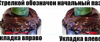
The winding order of any rotor depends on the number of slots in the rotor and the number of collector lamellas. You set the winding direction before disassembling and sketched it.
On the manifold, select the reference lamella. This will be the start of winding. Mark the starting lamella with a dot using nail polish.
Start of winding
When disassembling the rotor, we found that the rotor has 12 slots, and the collector has 24 lamellas.
We also established that the winding direction is clockwise when viewed from the commutator side.
Having installed insulating sleeves made of electric cardboard or its equivalent into the grooves, soldered the end of the winding wire to lamella No. 1, we begin winding.
The wire is placed in groove 1 opposite, and returns through the sixth groove (1-6), and so on until the required number of turns with a step of z=5. The middle of the winding is soldered to lamella No. 2 clockwise. The same number of turns is wound into the same section, and the end of the wire is soldered to lamella No. 3. One coil is wound.
How to rewind an electric motor armature at home
Before starting repairs, prepare the following tools and materials:
- multimeter If it is not there, then you will need a voltage indicator, a megohmmeter and a 12 V light bulb with a power of 30–40 W;
- new winding. The diameter of the core must be identical to the diameter of the old winding;
- soldering iron;
- dielectric cardboard 0.3 mm thick;
- varnish or epoxy resin;
- a skein of thick cotton threads;
- sandpaper.
In order not to do unnecessary work, it is important to correctly identify the cause of equipment failure. To do this, inspect the tool and check whether current is flowing to the collector and the start button using a multimeter or indicator. If everything is in order, then you need to inspect the device from the inside.
Engine diagnostics
Disconnect the tool from the power supply and disassemble the housing. Smell the rotor. If an interturn short circuit occurs, the insulating coating melts and emits a pungent odor.
When there are no external signs of malfunction, it is worth checking the armature lamellas with a multimeter. Switch the device to ohmmeter mode and set the range to 200 ohms. Using two probes, “ring” the adjacent lamellas. A change in resistance indicates a breakdown in the coil.
An ohmmeter can be replaced with a light bulb. Connect the plus and minus terminals to the plug of the device, and place a lamp in the gap. Rotate the armature shaft by hand. If the light blinks, it means that an interturn short circuit has occurred. Is the lamp not on? This means that there is an open circuit or there is no resistance in one of the lamellas.
Replacing the winding and new insulation will prevent the motor from burning out. To extend the life of the electric motor, it is recommended to rewind the rotor at least once every two years.
Instructions: how to rewind the armature winding
Before rewinding, you need to record the main indicators of the engine. Count and write down: the number of armature slots and commutator lamellas. Determine the winding pitch. The most common step 1-6 is when the coil is placed in the initial groove, then in 7 and secured to 1 groove.
Some factory windings use right or left reset. For example, when winding and discarding to the right, the coil moves to the right of the initial groove. So, when the number of armature slots is 12, the winding step is 1–6 and the reset is to the right, the winding is laid in 1 slot, then in 8 and after winding the required number of turns, it is fixed in 2 slots. All this needs to be taken into account. Otherwise, the winding will be laid incorrectly, which will negatively affect the direction of rotation.
Rewinding the armature of an electric motor with your own hands will take about 4 hours. To avoid any difficulties during assembly, it is recommended to photograph the original location of the parts during each stage of work:
- Determining the direction and initial winding groove. Find a coil on the winding that is not blocked by others. This is the last reel. If the winding lays to the right, it means that the initial groove is located to the right of the left side of the last coil. This is where you need to start laying the conductor. This way, the rewinding of the armature will be as close as possible to factory conditions. Mark the groove with a marker. With the initial symmetrical winding, the coils are laid in pairs, so there are also two last coils and initial grooves. They are also identified. To make finding grooves easier, pay attention to the image:
- Counting turns. It is necessary to determine the number of turns in the groove (W) and in the winding coil (K). Separate the top coil and count the turns. If necessary, the coil is fired in a burner flame. The nuance of the calculation is that the number of turns of an individual coil in a slot depends on the ratio of the number of collector lamellas to the number of armature slots. For example, the last coil has 60 turns (W), the armature has 12 slots, and the collector lamellas have 36. Then the value of K will be 10 (606), where 6 is the ratio of slots to lamellas, multiplied by 2.
- Preparing the collector. There is no need to remove it. Measure the resistance between the lamellas and the body. To do this, use a megohmmeter or switch the multimeter to the appropriate mode. The minimum resistance is 200 kOhm, the maximum is 0.25 MOhm.
- Dismantling the old conductor. Carefully, without damaging the armature body, remove the old winding.
- Cleaning the grooves and armature body. All carbon deposits and burrs must be sanded with sandpaper.
- Making sleeves for anchors. Cut rectangles from dielectric cardboard to match the size of the armature grooves.
- Rewind. Carefully review all notes made in preparation for the repair. The circuit for rewinding the armature with your own hands must fully correspond to the factory one. The end of the new winding is soldered to the end of the lamella. The wire must be laid from the initial groove, observing the pitch and winding reset.
How to center the rotor in a drill before grinding
The rotor is centered in the drill chuck to ensure minimal runout of the radial surface of the commutator relative to the rotor shaft.
First check the runout of the chuck jaws. Secure the drill in a vice, install a drill of the largest diameter in the chuck.
While rotating the drill, bring a pencil to the rotating side surface of the drill, resting it on a simple stop. With minimal runout, the pencil will draw a solid line on the surface of the drill. If the runout is significant, change the chuck in the drill or select a drill with less chuck runout.
Now, instead of a drill, clamp the rotor shaft and in the same way determine the runout locations of the rotor or commutator.
Commutator grinding process
The process of grinding the collector must begin with the selection of sanding material. It is recommended to use sanding paper or a file to sand the commutator.
Choose several sizes of sanding paper, starting from #100 and above.
Now start sanding. Applying a wooden block with sandpaper attached to the commutator, rotate the drill and, without pressing the block too hard to the surface of the commutator, grind.
Grinding the commutator in a drill
It is recommended to use the grinding operation on already operating rotors with minor wear on the commutator.
Proper brush sparking
If you have replaced the commutator on the rotor of the Makita 2470 rotary hammer, then after installing it on the shaft, the commutator must be machined. This operation is performed to eliminate radial runout of the surface of the lamellas of the new collector relative to the armature shaft.
It is best to grind the manifold on a lathe using mandrels. But this operation can also be performed at home. True, you can’t do it without an additional device. The video will help you understand the manifold groove.
As a rule, brush holders on hammer drills are mounted opposite each other. Prolonged operation of the brushes leads to the formation of grooves on the collector, creating waviness on the surface. Such wear can only be eliminated on a lathe by turning the commutator.
To reduce the formation of grooves on the commutator, you should try to arrange the brush holders in a checkerboard pattern.
Where to begin?
Since the structure of the rotary hammer is simple, the repair of the makita rotary hammer must begin with its disassembly. It is best to disassemble the hammer drill according to the already proven procedure.
Algorithm for disassembling a hammer drill:
- Remove the back cover on the handle.
- Remove the electric carbon brushes.
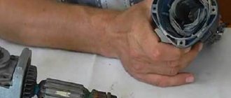
- Disconnect the mechanical block housing and the stator housing.
- Disconnect the rotor from the mechanical unit.
- Remove the stator from the stator housing.
Remember, the stator housing is green, the mechanical unit housing with the rotor is black.
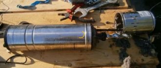
Having disconnected the rotor from the mechanical unit, we proceed to determine the nature of the malfunction. Rotor Makita HR2450 pos.54; article 515668-4.
How to find a short circuit in the rotor
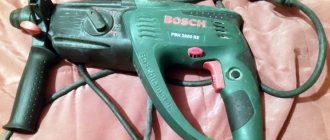
Since you are repairing rotary hammers yourself, you need an electrical diagram for a Makita 2450, 2470 rotary hammer.
Makita 2470, 2450 rotary hammers use AC commutator motors.
Determining the integrity of a brushed motor begins with a general visual inspection. The faulty rotor pos. 54 shows traces of burnt windings, scratches on the commutator, and traces of burning on the commutator lamellas. A short circuit can only be detected in a rotor whose circuit does not have an open circuit.
To determine a short circuit (SC), it is best to use a special device IK-32.
Checking the armature for short circuit using a homemade indicator
After making sure, using the specified device or a homemade device, that the rotor has a short circuit between the turns, proceed to disassemble it.
Rotors before disassembly
Before disassembling, be sure to fix the winding direction. This is done very simply. Looking at the end of the rotor from the commutator side, you will see the winding direction. There are two winding directions: clockwise and counterclockwise. Record and write down, you will definitely need this data when winding yourself. The rotor of the Makita rotary hammer has a clockwise winding direction, right.
How to repair an anchor at home
A third of screwdriver failures occur due to the anchor. With everyday intensive operation, malfunctions can occur within the first six months, for example, if the brushes are not replaced in a timely manner. With gentle use, the screwdriver will last a year or more.
The anchor can be saved if the balance is not disturbed. If during operation of the device you hear an intermittent hum and there is strong vibration, then this is an imbalance. This anchor must be replaced. And the winding and commutator can be repaired. Small short circuits are eliminated. If a significant part of the winding is damaged, it can be rewound. Worn and badly damaged lamellas should be sharpened, extended or soldered. In addition, you should not undertake anchor repairs if you are unsure of your capabilities. It is better to replace it or take it to a workshop.
Collector groove
Over time, wear from the brushes forms on the commutator. To get rid of it, you need to:
- Grind the commutator using cutters for longitudinal grinding, that is, through cutters.
Passing straight cutter
Don't forget to clear the rotor of chips to prevent a short circuit.
Video on the topic
How to rewind an anchor
Before disassembling the armature, write down or sketch the direction of the winding. It can be left or right. To determine it correctly, look at the end of the armature from the commutator side. Wear gloves and take sharp wire cutters or a hacksaw. Remove the winding end parts. The collector needs to be cleaned, but it is not necessary to remove it. Carefully, without damaging the slot insulators, knock out the rods of the remaining parts of the winding using a hammer and metal chisel.
Video: Removing the winding
Using a needle file, without damaging the insulator film, remove the remaining impregnation. Count the conductors in the slot. Calculate the number of turns in the section and measure the diameter of the wire. Draw a diagram. Cut cardboard sleeves for insulation and insert them into the grooves.
Video: Winding left and right
After winding, weld the section leads to the collector cocks. Now check the winding with a short circuit tester and indicator. Proceed with impregnation.
Instructions for impregnation (taking into account the speed controller)
- After making sure that there are no problems, send the armature to the electric oven to warm up for better flow of the epoxy resin.
- After warming up, place the anchor on the table at an angle for better spreading over the wires. Apply resin to the frontal area and slowly rotate the anchor. Drip until glue appears on the opposite frontal part.
Impregnation at an angle
Drying the anchor in air before polymerization
At the end of the process, lightly grind the commutator. Balance the anchor using a dynamic balancer and an angle grinder. Now make the final grind on the bearing. It is necessary to clean the grooves between the lamellas and polish the collector. Make a final check for opens and shorts.
The peculiarity of the winding for angle grinders with adjustable speed is that the rotor is wound with a power reserve. Current density affects the number of revolutions. The wire cross-section is too high and the number of turns is too low.
How to check the condition of the brushes
When installing new carbon brushes, it is recommended to grind them in for a better fit to the commutator surface.
It is best to adjust carbon brushes using a homemade grinder. The lap is a shaft on which sandpaper is attached. The easiest way is to make the shaft from wood with a diameter equal to the diameter of the commutator, turning the workpiece on a lathe. A metal rod is inserted tightly along the axis inside the shaft. The device is attached to the chuck of an electric drill, the drill is turned on, and the brushes are brought to a rotating emery wheel.
The adjustment should be carried out carefully, periodically applying the brushes to the rotor commutator to check their clearance.
Having ground the brushes to the commutator, it is recommended to check the correct fastening of the brush holders before installation. When factory installed, the brush holders are set to neutral, which minimizes sparking on the commutator. If there are no factory marks, then the installation of the brush holders is adjusted by moving the brush holder in the direction opposite to the rotation of the rotor until a minimum spark is formed.
The brushes should not dangle in the brush holder, but should be pressed tightly against the commutator lamellas. The pressing force is regulated by springs in the brush holder.
Sparking faulty collector
An increase in sparking on the rotor commutator may appear due to a short circuit of the armature, a break in the armature coils, or a short circuit of the windings to the armature body. All these faults can be eliminated only with a major overhaul of the rotor.
How to check with a multimeter
- Set the resistance to 200 ohms. Connect the probes of the device with two adjacent lamellas. If the resistance is the same between all adjacent plates, then the winding is working. If the resistance is less than 1 ohm and very close to zero, there is a short circuit between the turns. If the resistance is two or more times higher than average, then there is a break in the winding turns. Sometimes when there is a break, the resistance is so great that the device goes off scale. On an analog multimeter, the arrow will go all the way to the right. But digital won’t show anything.
Diagnosis of the armature winding with a multimeter
- The determination of breakdown to ground is made in the absence of a winding break. Set the device scale to maximum resistance. Depending on the tester, it can be from 2 MOhm to 200 MOhm. Connect one probe to the shaft, and the other to each plate in turn. If there are no faults, the resistance should be zero. Do the same with the rotor. Connect one probe to the iron rotor body, and move the other along the lamellas.
Video: how the check is carried out
If you don't have a tester, use a 12-volt light bulb with up to 40 watts.
How to check the rotor of an angle grinder using a light bulb
- Take two wires and connect them to the lamp.
- Make a break on the negative wire.
- Apply voltage to the wires. Place the ends of the break against the collector plates and rotate it. If the light bulb lights up without changing brightness, then there is no short circuit.
- Perform a short circuit test to the iron. Connect one wire to the lamellas and the other to the rotor iron. Then with the shaft. If the light is on, it means there is a ground fault. The winding closes to the rotor housing or shaft.
This procedure is similar to diagnostics with a multimeter.
Features of the asynchronous motor of the angle grinder
Almost all electrical appliances used in everyday life use an asynchronous electric motor. An important advantage of this type of motor is that when the load on it changes, the speed does not change. This means that if, for example, you cut stone for a long time and without stopping with a household grinder, there will be no noticeable external signs of engine overload. The disk rotation speed will be constant, the sound will be monophonic. Only the temperature will change, but this may not be noticed if your hands are wearing gloves.
If you are not careful, an advantage can turn into a disadvantage. Asynchronous motors are very sensitive to overheating; a significant increase in operating temperature entails melting of the insulation on the rotor windings. At first, the motor will work intermittently, and then - when an interturn short circuit occurs - the motor will stop completely. If you overheat the grinder's engine several times, it is most likely that the anchor will melt. In addition, the high temperature causes the contacts connecting the wires of the primary winding to the collector to become unsoldered, which leads to an interruption in the supply of electric current.
How to check the angle grinder's anchor for serviceability
Types of armature faults:
- Breakage of current conductors.
- Interturn closure.
- An insulation breakdown to ground is a short circuit of the winding to the metal rotor body. Occurs due to the destruction of insulation.
- Wiring of collector terminals.
- Uneven wear of the commutator.
If the armature is faulty, the motor overheats, the winding insulation melts, and the turns become short-circuited. The contacts connecting the armature winding to the collector plates are unsoldered. The current supply stops and the motor stops working.
Types of armature diagnostics:
- visually;
- multimeter;
- light bulb;
- special devices.
Standard diagnostics
Before taking the diagnostic device, inspect the anchor. It may be damaged. If the wiring is melted, the burnt insulating varnish will leave black marks or a specific smell. You may see bent or crumpled coils or conductive particles, such as solder residue. These particles cause short circuits between turns. The lamellas have curved edges, called cockerels, to connect to the winding.
Cockerel lamellas
Due to disruption of these contacts, the lamellas burn out.
Burnout of the lamella
Other commutator damage: raised, worn or burnt plates. Graphite from the brushes may accumulate between the lamellas, which also indicates a short circuit.
Bent commutator plates
Troubleshooting
DC rotors of screwdrivers, mixers and fans are either commutator or brushless. With the latest motors, the windings located on the stator are switched using a controller. Therefore, before rewinding, you need to make sure that the keys and the controller itself are in good working order. AC electric motors are divided into:
- asynchronous with squirrel-cage rotor;
- synchronous or brushed with a wound rotor.
To determine the malfunction of the rotor windings, a special induction device is used. You can determine if the windings of an asynchronous motor are damaged using a tester or an ohmmeter. Sometimes specialized electronic devices are used to detect short-circuited turns.
Rotor failure is most often due to a short circuit in the armature. By unsoldering the conductors from the contact group and checking them for a short circuit, they find a fault in the contacts or rotor turns. In case of short circuit of the latter, the breakdown is eliminated by replacing the wire. If there are few turns, and the rotor wire is thick and without damage, then make it well insulated by placing a plate of cardboard or fabric moistened with insulating varnish.
If there is a short circuit in the contact group, it must be repaired or replaced. You can cut a thin groove between the closed contacts and insert a textolite plate glued with epoxy glue. Use sandpaper to remove irregularities on the contact group.
How to determine if an angle grinder's armature is faulty
Signs of a broken armature angle grinder are: increased sparking of the brushes on the motor commutator, vibration of the motor at low speeds, rotation of the working shaft in different directions. If such symptoms are present, you should stop using the tool - this is dangerous. Suspicions can be easily verified using simple tests.
Visual inspection from outside
Troubleshooting should begin with a visual inspection of the angle grinder:
- Carry out a general inspection of the instrument.
- Pay attention to the integrity of the power cord and the presence of voltage in the outlet.
- Using a voltage indicator, make sure that current is flowing to the motor commutator and the start button.
Inspection of the device from the inside
If everything is in order with the power supply, but the angle grinder does not work, you will have to open the case to gain access to the motor. As a rule, disassembly is not difficult. But you need to follow simple rules that will help you avoid troubles during reassembly:
- Be sure to disconnect the device from the mains before disassembling.
- Remove the working disk and protective cover from the spindle.
- Open the case in a well-lit place, on a clean table surface.
- Remember the location of all parts and assemblies before disassembling. It is recommended to sketch or photograph the internal structure of the device.
- Place screws and fastening screws in a separate place so that they do not get lost.
It is best to inspect the engine under bright lighting so that all small parts are clearly visible. The armature should rotate freely around its axis; properly functioning bearings should not make any sound during operation. There should be no traces of melted wiring on the armature, the circuit windings should be intact, without breaks. You can smell the rotor. When there is an interturn short circuit, the insulating varnish burns and emits a persistent specific odor. But such a diagnosis requires some experience.
Continuity testing of circuits with a tester
If a visual inspection does not give clear results, it is recommended to continue the examination using a multimeter. Having set the mode switch to the ohmmeter position (200 Ohm range), you need to “ring” two adjacent armature lamellas with two probes. If the resistance on all turns is the same, this means that the windings are working properly. If on some pairs the tester shows a different resistance or an open circuit, there is a malfunction in this coil.
Checking the commutator motor with a multimeter
Let's say a visual inspection did not produce results - at first glance, all components are intact, no breaks were found, and there is no burning smell. In this case, check the device and its elements using a special device - a multimeter. The process consists of several stages:
- Set the device to resistance measurement mode up to 200 Ohms.
- Ring the paired terminals of the stator windings on the lamellas. The resistance values must be the same.
- Check the armature body and lamellas. Ideally, the resistance value tends to infinity.
- Ring the winding terminals. If there is no resistance in one or more circuits, the motor is faulty.
- Check the circuit between the stator housing and the winding terminals. If there is a breakdown in the housing, operation of the unit is impossible.
- Ring the rotor by placing the tester probes on the commutator at the maximum distance from each other. When the multimeter shows a value, turn the rotor slightly until the probes connect to the next winding. Check all windings in this way. If the resistance value in each circuit is the same or differs very slightly, the unit is working.
In what cases can you save an anchor and restore it yourself?
If damage to the armature is determined with guaranteed accuracy, the part must be removed from the electric motor. Disassembling the motor must be done with special care, after removing the brushes and disconnecting the power terminals. The rotor is removed along with the support bearings and the motor cooling impeller; they form a single whole with it.
If most of the wiring in the armature is damaged and the balancing is disrupted as a result of overheating, it is better to replace it entirely. An imbalance is indicated by increased vibration and an uneven hum when the mechanism operates.
How to rewind an anchor - step-by-step instructions
If the balancing of the armature is not disturbed, and the problem is only in damaged windings, then such an armature can be restored independently by rewinding the coils. Rewinding a rotor at home requires a lot of patience and accuracy.
The technician must have skills in working with a soldering iron and instruments for diagnosing electrical circuits. If you are unsure of your abilities, it is better to take the engine to a workshop for repairs or replace the entire armature yourself.
To rewind the anchor yourself you will need:
- wire for a new winding. A copper core with a diameter exactly matching the old conductor is used;
- dielectric paper for insulating the winding from the core;
- varnish for filling coils;
- soldering iron with tin-lead solder and rosin.
Before rewinding, it is important to count the number of turns of wire in the winding and wind the same amount of new conductor onto the coils.
The rewinding process consists of the following steps:
- Dismantling old windings. They must be carefully removed without damaging the metal body of the armature. If any burrs or damage are found on the body, they must be smoothed out with a file or sanded with emery. Sometimes, to completely clean the body of slag, craftsmen prefer to burn it with a torch.
- Preparing the collector for connecting a new wire. There is no need to remove the manifold. You should inspect the lamellas and measure the resistance of the contacts in relation to the housing with a megger or multimeter. It should be no more than 0.25 MOhm.
- Removing old wiring on the manifold. Carefully remove the remaining wires and cut grooves in the contacts. In the future, the ends of the coil wires will be inserted into the grooves.
- Installation of sleeves for anchors. The sleeves are made of dielectric material 0.3 mm thick, for example, electrical cardboard. Cut a certain number of sleeves and insert them into the grooves of the cleaned anchor.
- Rewinding reels. The end of the new conductor is soldered to the end of the lamella and wound in successive circular movements, counterclockwise. This laying is called “laying to the right.” Winding Repeat for all coils. Near the collector, tie the wires together with a thick thread of cotton fabric (it is prohibited to use nylon, as it melts when heated).
- Checking the winding quality. After laying all the windings, check with a multimeter for the absence of interturn short circuits and possible breaks.
- Finishing processing. Treat the finished coil with varnish or epoxy resin to secure the winding. In factory conditions, the impregnation is dried in special ovens. You can do this at home in the oven. As an option, use quick-drying varnishes for impregnation, applying the coating in several layers.
Do-it-yourself collector repair using galvanic extension
Do-it-yourself collector repair using galvanic extension
This is what collectors look like that are quite suitable for restoration.
To the left, from the stove, with the lamellas completely burnt out to the insulator, you will have to wind a bare wire with a diameter of about 0.2 mm onto it turn to turn. In the middle of the starter, but already machined for extension. It shows that one lamella has burned out to the base and the rest are extremely worn, but the fastening of the lamellas is not broken, and the wires are welded to the lamellas. Standard diameter 45mm machined to 41mm. On the right, the manifold is also from the stove, quite suitable for restoration without modifications, you just need to clean it.
The anchor for the extension will have to be prepared, since it is not quite ordinary, and an improvised bathtub will have to be made.
Half a plastic bottle is suitable for this. The armature shaft needs to be wrapped with tape, and the end of the commutator should be covered with plasticine so that copper does not accumulate on the ends of the lamellas in vain and so that the electrolyte does not leak between the shaft and the insulator of the commutator; contact of the electrolyte with iron is unacceptable. You need to wind a cork from PVC electrical tape so that it fits tightly into the neck of the bottle from the inside. At the motor commutator, you need to use a piece of bare wire to connect all the lamellas well together and hang them on the crossbar in a simple jar of electrolyte so that the electrolyte does not touch the hooks, but completely covers the area of wear. The location of the collector is in the electrolyte, the anode is a tire from a burnt-out starter, its total area should be approximately twice as large as the surface to be built up. The shank is rolled up into a spiral, slightly larger than the diameter of the vessel and, when placed in the vessel, fits tightly to the wall. The minus of the power source is connected to the extension part, the plus to the busbar. The current is selected at the rate of 1.5A per 1 dm2. You can power it from a phone charger, and regulate the current by turning on light bulbs of different power in series. Light bulbs are also needed to protect against possible short circuits in the bathtub. Electrolyte composition:
- copper sulfate - 200g
- sulfuric acid 1.84 - 40g
- alcohol - 5g
- boiled water - 800ml.
- alcohol can be replaced with triple the amount of vodka.
A day later we get a not entirely attractive appearance of the extended collector.
But after grooving it already looks like this, since copper builds up, although not evenly, but much more than necessary.
Of course, the volume of the bath is small, you can experiment with the composition of the electrolyte, but is this necessary? With this mode, the copper builds up to be very hard, although not evenly. You can cut the grooves between the lamellas with a drill, or simply with a sharpened hacksaw blade, and be sure to check for the absence of short circuits between the plates.
This is what the starter armature, ready for assembly, looks like, its diameter has become 1 mm larger than the standard one, but this does not interfere with anything, but takes longer. You can see by a small chip where the burnt lamella was. On the right is the motor armature ready for winding, the collector is also enlarged by 1 mm. This method can be used to restore almost any collector, unless, of course, it fell apart.
Working with the stator
First, they draw up a diagram of the location and connection of the electric motor windings. If the motor is three-phase, then carefully draw up a diagram of the coils for each phase. They are usually wound with one wire. Only after a good study and correct drawing up of the winding connection diagram can you begin to disassemble and remove them. It is better to mark the windings with different paints and take photographs. You also need to check whether you can figure it out from photographs and diagrams.
Before rewinding the electric motor stator, a template is made according to its size. The width is equal to the size between the grooves into which the coil will fit. To isolate the stator from the winding, plates made of cardboard or special insulating material are inserted into the grooves. When laying the coil in the grooves, use a wooden or plastic spatula - a tamper.
After winding one coil, the wire is not bitten off, the coil is placed in the grooves and continues to be wound onto the template . All coils of the same phase are wound with a solid wire without cutting it. First, rewind all the turns of one of the phases, placing them one by one. The coils for the remaining phases are wound and laid in the same way. The upper part of the winding in the stator slots above the turns is covered with plates of the same insulating material as in the stator slots themselves.
After winding and laying the coils of one of the phases, they must tie them and form the coils into even bundles, trying to ensure that the turns are in one bundle and do not touch the stator housing. If the coil is too big and touches the body, then a cut cambric is put on it and then tied. Touching the housing wires outside the insulation is unacceptable, since vibration from the electromagnetic field can cause the varnish to rub off, causing the coil to short-circuit to the housing. After installation, check the resistance with an ohmmeter.
Angler anchor device
The armature of the angle grinder motor consists of a conductive winding and a magnetic circuit into which the rotation shaft is pressed. It has a drive gear at one end and a commutator with lamellas at the other. The magnetic core consists of grooves and soft plates coated with varnish to insulate them from each other.
Grinder anchor diagram
Two conductors of the armature winding are laid in the grooves according to a special pattern. Each conductor makes up half a turn, the ends of which are connected in pairs on lamellas. The beginning of the first turn and the end of the last are in the same groove, so they are closed to one lamella.
Collector lamellas
Replacing the anchor yourself at home
Practice shows that if you decide to replace the armature of an angle grinder, then it is best to change it together with the support bearings and the engine cooling impeller.
To replace you will need:
- New angle grinder anchor. Must match your model. Interchange with other models is not permitted.
- Screwdrivers, wrenches.
- A soft brush and cloth for wiping the mechanism.
How to remove an anchor
Replacing the anchor begins with disassembling the angle grinder. The following steps are performed:
- Use a screwdriver to unscrew the brush units on both sides. The brushes are removed.
Video: replacing bearings on an angle grinder
How to put an anchor in place
To install a new angle grinder anchor in place, you should take a new part, and then assemble the tool in the reverse order. The sequence of actions is as follows:
- A fixation disk is installed on the armature shaft.
- The bearing is installed using the pressing method.
- The small gear is fitted and secured with a retaining ring.
- The anchor is inserted into the gearbox housing, and the docking holes are aligned.
- The gearbox mounting bolts are tightened.
- The anchor with the gearbox is inserted into the body of the angle grinder and fixed.
- The brushes are deposited in their places and closed with lids.
Electric motor armature repair
Scheduled preventive maintenance of an electric motor armature is carried out after a certain period of its operation. As a rule, it includes the restoration of the movable contact group (collector). In cases of sudden failures or significant deviations in the operation of the electric motor, urgent repairs of the electric motor armature may be carried out. The basis for such repairs may be one of the reasons or a combination of them:
- strong sparking at the point of contact of the brushes with the commutator;
- reduction in engine power;
- increased heating of the case.
To repair the electric motor armature, it must first be dismantled. After this, the anchor removed from the engine is carefully inspected to identify burnouts, melting, breaks, and other visible defects. During a visual inspection, pay attention to the integrity of the windings (local blackening), the degree of contamination of surfaces with graphite dust, and foreign (characteristic) odors of burning insulation.
Check and enable
Before starting the engine for the first time after repair, it must be thoroughly checked. To begin with, all inserted “coils” ring. This will help you find out if there is a break or poor contact. The resistance is measured between the “layings” so that a short circuit does not occur when turned on.
You should not immediately supply 220 V to the engine; it is better to supply a reduced voltage. Let the rotor spin slowly, the main thing here is to find out if the engine is overheating. If everything went well and no smoke appeared, then the engine repair was successful.
There are many photos on the Internet on rewinding motors. This will help beginners visually familiarize themselves with the process.
Where to rewind the armature of an electric motor
It is possible to rewind the armature of an electric motor efficiently only using special equipment. This technological operation is similar in complexity to rewinding the stator. Our workshop has the necessary tools and equipment for rewinding commutator motor armatures.
An anchor is a movable structural element that rotates at a high angular velocity. In this regard, it is affected by significant centrifugal forces. Therefore, rewinding of the electric motor armature must be complemented by its high-quality balancing. After rewinding the electric motor, impregnation and drying, it is necessary to carry out the final operation - dynamic balancing of the armature on a special balancing machine. Neglecting this will lead to significant vibration, destruction of bearings and armatures.
The price for work on rewinding an electric motor armature will always be lower than for the purchase of a new electric power unit. In many cases, restoring the electric motor armature is the only way to repair the electric drive, since selecting a new commutator motor can be difficult due to the characteristics of the installation location.
The cost of repairing an electric motor armature in Moscow at our company’s production facilities depends on the type of engine, the nature of the damage and the urgency of the work. Approximate prices can be found in the price list on the website page.
Do-it-yourself static balancing of the electric motor armature
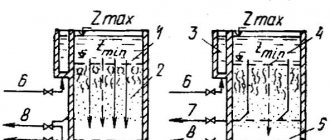
The key to uninterrupted operation of the equipment after rewinding the armature is proper balancing. In large electric motor repair companies, dynamic balancing is done on a special machine. Since it is difficult to rewind the anchor yourself for the first time, the device for static balancing “On Knives” will help to identify gross errors. It is easy to design it yourself.
Pick up two steel blades. They must have good straightness and cleanliness. Place the blades on a rigid base parallel to each other. The distance between the blades is the size of the anchor. The result should be something like this:
Schematic representation of the “On Knives” device, where 1 is the armature of the electric motor; 2 — steel blades; 3 - base; A and B are points for soldering weights.
The balancing method is simple: the anchor is placed on the blades and its movement is observed. The anchor will rotate because the heaviest part will be at the bottom. The task is to move the center of gravity as close as possible to the axis of the anchor, which is indicated by the dotted line. With high-quality balancing, the anchor remains motionless. To equalize the weight, plasticine weights are hung on points A and B. When equilibrium is achieved, the weights are removed, weighed, and metal equal to their weight is soldered.
Now you know how to rewind an anchor with your own hands. Thanks to balancing skills, your instrument will not vibrate and overheat, even with minor flaws in the winding installation. Regular checking of contacts and routine cleaning of the housing will help minimize the likelihood of equipment breakdown.
Preparatory work
First, let's figure out how to properly rewind an electric motor. The first thing to do is determine the parameters of the wire and the number of turns in the coil. The Internet will help here. On forums, people discuss similar problems, and also talk about personal experiences of how they rewound engines.
IMPORTANT! It is necessary to find the exact same model of the device, otherwise, after repair, the “engine” may not start!
If you don’t have the necessary information on the Internet, you can find it out yourself when inspecting the engine. In case of severe burnout of the “layings”, we find the most complete section of the winding. It needs to be cleaned.
To remove carbon deposits from wires, use solvents. Now you shouldn’t feel sorry for the “coils”, they are no longer suitable. If you cannot clean the winding with solvent, you can burn it.
There are various schemes for rewinding electric motors. Before removing the “coils”, you should pay attention to how they are connected to each other. And then you can exactly copy their assembly.
The protruding top of the “laying” must be cut off. To do this, we will prepare the appropriate tool, it all depends on the cross-section of the wire. The larger it is, the more serious the tool will be needed. The cut part must be divided into separate wires. This makes it more convenient to determine the cross-section and number of turns.
Having removed the winding, we check the iron on which it was wound. The steel should be smooth without dents or burrs. Defects can damage the insulating layer of copper wires, which will lead to another breakdown. Therefore, all irregularities should be smoothed out with sandpaper.
If there is carbon deposits in the steel grooves, you should also get rid of it. This will help avoid further difficulties when working with insulation and wires.
Prices for repairing an electric motor armature
| Power, kWt) | Rotation speed, rpm | |||
| 3000 | 1500 | 1000 | 750 | |
| Up to 1.5 | 2740 | 2806 | 3417 | 4057 |
| 2.2 | 3090 | 3245 | 4154 | 4897 |
| 3 | 3642 | 3901 | 4973 | 5179 |
| 4 | 5012 | 4652 | 5413 | 6804 |
| 5.5 | 5296 | 5301 | 5978 | 7511 |
| 7.5 | 6630 | 6919 | 7312 | 11021 |
| 11 | 8139 | 8147 | 9937 | 13182 |
| 15 | 12088 | 12049 | 11737 | 14803 |
| 18,5 | 13001 | 13345 | 15217 | 24450 |
| 22 | 15057 | 15805 | 23408 | 25522 |
| 30 | 17648 | 18202 | 25857 | 29275 |
| 37 | 23803 | 25949 | 30677 | 40080 |
| 45 | 29055 | 28737 | 38389 | 48070 |
| 55 | 34546 | 32811 | 41481 | 60759 |
| 75 | 44670 | 48812 | 64472 | 82899 |
| 90 | 47893 | 51078 | 78166 | 99898 |
| 110 | 67202 | 73052 | 95759 | 122517 |
| 132 | 80848 | 87962 | 114110 | 147423 |
| 160 | 98012 | 106439 | 138740 | 179116 |
| 200 | 123101 | 132548 | 173924 | ———- |
| 250 | 154120 | 167435 | ———- | ——— |
| 320 | 237156 | ————— | ———- | ———— |
| kW | 3000 rpm | 1500 rpm | 1000 rpm | 750 rpm |
COEFFICIENTS USED IN THE CALCULATION:
- Single-phase - 1.5;
- Foreign production -1.5;
- Explosion-proof – 1.3;
- Urgent – 1.5;
- Two-speed – 1.5; Two-speed with independent windings – 2.
- Old model type AO, A, VAO -1.5
Source