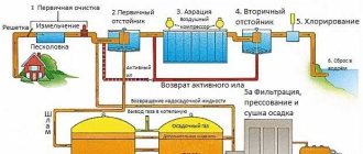
Filtration is the process of cleaning household waste by passing them through special screening devices (filters). A wastewater filter is a stationary or portable device that filters small and large impurities contained in water. What filters are used to clean household wastewater and how to independently set up a filtration system in a suburban area, read on.
Installation for wastewater treatment using filtration method
Filters with floating (plastic) loading FPZ
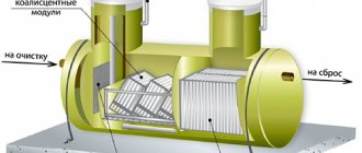
FPZs are relevant for the post-treatment of mechanically treated industrial wastewater, biologically clarified urban waters, and mixtures of domestic and industrial wastewater. In terms of BOD and suspended matter, filters with floating loading give the same results as filters with 2-layer loading. FPZs can operate with water directed downwards and upwards, with and without reagents, in gravity, pressure and combined systems. The device diagrams are presented below.
Rice. Filter circuits FPZ-3 and FPZ-4 with floating loading
1 – body; 2 – floating load; 3 – filter pocket; 4 – holding grid; 5 – lower drainage system; 6 – supply of source water; 7 – drainage of wash water; 8 – filtrate discharge.
Flushing of the FPZ is carried out when there is a critical loss of pressure. The procedure is performed with a downward flow of purified water. To prevent biological fouling of the load, you need to wash it every month for 24 hours with chlorinated water: 300 grams per 1 liter.
Advantages of MFB:
- simple design;
- ease of use;
- possibility of full automation of the working module;
- high-quality cleaning result;
- ease of washing;
- long loading life;
- large FPZ resource.
Types of industrial treatment facilities
Regardless of the post-treatment technology used at a particular enterprise, the principle is the same - in post-treatment facilities, wastewater passes through filter media, which come in three types:
- Inert. They do not form a chemical reaction with wastewater. As the wastewater passes through the load, contaminants remain in the filter mass.
- Sorptive. Contaminants are absorbed by the filter particles.
- Ion exchange. An ion exchange process occurs between the filter and the harmful components of the wastewater, as a result the structure of the liquid changes.
From a design point of view, industrial wastewater treatment plants are divided into:
- pressure;
- non-pressure;
- equipped with counterflow;
- with forced flushing function.
Loading blocks are installed in containers made of fiberglass, reinforced concrete, stainless steel or ferrous metal. Restoration of the filter layer is carried out by water/reagent washing or cleaning with a mixture of water and air.
Bubbler froth flotation units for surfactant effluents
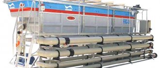
Equipment in this category is used for post-treatment of wastewater before discharge into a reservoir or use of water in the technical return water supply system of industrial enterprises. The units effectively remove synthetic surfactants, reduce the concentration of suspended matter, and eliminate residual organic matter. The equipment diagram is presented below.
Rice. Diagram of a bubble flotation plant
1 – flotation tank; 2 – supply of source water; 3 – compressed air supply; 4 – overlap; 5 – centrifugal fan; 6 – foam collector; 7 – removal of foam product; 8 – removal of purified water; 9 – partition; 10 – aerators; 11 – emptying the flotation tank.
It is recommended to use fine-pored aerators or compressed air supply pipes with OS in the equipment. A centrifugal fan collects and extinguishes foam. The choice of cooler model should be made according to the air consumption per hour. For working calculations, it is advisable to use the data from the table below.
| Specific air consumption per 1 m3 of water, m3/m3 | 3,5 – 4 |
| Bubbling intensity, m3/(m2 h) | 35 |
| Bubbling duration, min | 30 |
| Working height of water layer, m | 3 – 5 |
| Air consumption per filter plate, l/min | 100 – 120 |
| Air consumption per 1 meter of filter tube length (d=234mm), m3/h | 10 – 20 |
| Volumetric mass of foam, kg/m3 | 2,1 – 2,6 |
| Speed of foam movement at the point furthest from the fan, m/s | 0,7 |
| Composition of foam product, g/l | |
| suspended solids content | 1,8 – 4 |
| BOD5 | 2,1 – 5 |
| COD | 18 – 25 |
| Surfactant | 0,5 – 3 |
The collected foam masses are processed together with sewage sludge on vacuum filters. Next they undergo thermal drying. To prevent surfactants and sludge liquid from being carried away, it is necessary to add a foam product to the fermented, washed, compacted sludge. It does not affect the performance of the equipment, the moisture content of the sludge, or the operation of the reagents. The sludge with the foamy product can be used as fertilizer for plants.
If the liquid contains biological soft surfactants and intermediate groups are periodically introduced, the foam product is processed by returning to the aeration tank. The surfactant concentration is determined as follows:
where Cpost is the concentration of surfactants entering the aeration station, mg/l; B – efficiency of surfactant removal during biological treatment, %; D – efficiency of surfactant removal during wastewater tertiary treatment in froth flotation units, %.
Our advantages
- We solve problems of any complexity
- Guaranteed results
- We approach each task individually
- We produce equipment in our own production
- We carry out pilot and laboratory tests on real wastewater
- We save your budget through optimal solutions
- Wide range of equipment options
- We ship equipment on time
- Own developments in production
- Extended warranty up to 5 years
- We provide warranty and post-warranty service
- We constantly improve and implement advanced domestic and foreign developments
- We protect your company from the onslaught of regulatory authorities
The task of the company’s specialists is to develop a technological process, select the necessary range of equipment and, if necessary, physically implement the developed project for treating industrial wastewater. It is possible to use standard equipment and technologies, as well as to develop, if necessary, individual solutions. The key area of activity of the Research and Production Center is water treatment and wastewater treatment of industrial enterprises. Depending on the requirements for water quality and the specifics of production, technological chains can vary greatly from each other.
Effective collaboration
In the catalog of NPC PromVodOchistka you can see the range of standard equipment. Along with our own developments, models from the world's leading manufacturers are presented. The sections provide a brief description, purpose and technical characteristics of the installations. You can check with the company’s specialists about delivery times, costs and additional information on items of interest.
If it is impossible to select a standard solution for any task, it is possible to develop non-standard options for industrial wastewater office systems. This can be either the design of non-standard installations, the selection of reagents and processing modes, or the manufacture of non-standard equipment.
As part of service support, it is possible to carry out a full range of installation, commissioning work and organize warranty and post-warranty maintenance of installed equipment.
All company activities are certified in accordance with ISO 9001 quality standards. The company's personnel have the appropriate knowledge and qualifications to find optimal technical and technological solutions to obtain optimal results.
Bubble and pressure flotation plants for post-treatment of wastewater after biological treatment
This technique can be used to purify water from surfactants and residual organics. Sparging is carried out with flocculation if the recirculation foam is between 30 and 50%. In some cases, the procedure can be performed without recirculation and flotation.
Flotation with flocculation weakens the hydrophilic properties of the surface of suspensions, which increases their ability to adhere to air bubbles. The treatment process using recirculation and flocculation guarantees a higher effect of wastewater tertiary treatment. The installations consist of several working models:
- two or more flotators;
- pumping or pumping station;
- mixer;
- reagent supply system;
- receiving containers.
The equipment diagram is shown in the figure below.
Rice. Bubble flotation unit
1 – mixer; 2 – flotator; 3 – foam reservoir; 4 – removal of treated wastewater; 5 – aerators; 6 – supply of biologically treated wastewater; 7 – flocculant supply; 8 – air supply; 9 – supply of biologically treated wastewater with flocculant from the mixer to the flotator.
Post-treatment of wastewater in bubble flotation units is carried out according to the scheme presented in the following figure.
Rice. Scheme of the movement of water (a) and foam (b) through a bubble flotation installation
1 – mixer; 2 – flotator; 3 – supply of biologically treated wastewater; 4 – flocculant supply; 5 – supply of biologically treated wastewater with flocculant from the mixer to the flotator; 6 – air supply; 7 – aerators; 8 – discharge of post-treated wastewater; 9 – contact tank; 10 – purified water outlet; 11 – pumping station; 12 – foam reservoir; 13 – removal of foam to the aeration tank.
For bubble flotation, a rectangular settling tank is used, into which water is supplied from above at a speed of 3 mm/sec. Removal is carried out from below. Aerators for supplying air under pressure from 0.15 to 0.2 MPa are located at the bottom. Trays for collecting foam are installed at the top.
For pressure flotation, it is advisable to choose round settling tanks with a built-in chamber, at the bottom of which two water distributors are installed. They rotate: one supplies source water, the other supplies recirculated water with air. The water in the installation lasts from a quarter of an hour to 20 minutes at an ascending speed of 2-3 mm/sec, and at a descending speed of 1.3 mm/sec - from 10 to 15 minutes. The scheme for post-treatment in a pressure flotation unit is shown in the diagram below.
Rice. Flotator for post-treatment of biologically treated wastewater with a capacity of 2000 m3/h.
1 – supply of wastewater with flocculant; 2 – supply of recirculation water; 3 – waste water distributor; 4 – recirculation water distributor; 5 – flotation chamber; 6 – settling zone; 7 – ring drainage tray; 8 – mechanism for raking foam; 9 – foam collection trays; 10 – sediment removal; 11 – foam removal; 12 – outlet pipeline.
Rice. Schemes of the movement of water (a) and foam (b) through a pressure flotation installation.
1 – waste water supply; 2 – flocculant supply; 3 – mixer; 4 – ring drainage tray; 5 – settling zone; 6 – flotation chamber; 7 – waste water distributor; 8 – recirculation water distributor; 9 – recirculation water tank; 10 – pumping station; 11 – contact tank; 12 – outlet pipeline; 13 – supply of post-treated wastewater for recycling; 14 – supply of recirculation water; 15 – supply of wastewater with flocculant; 16 – foam collection trays; 17 – foam removal; 18 – foam reservoir; 19 – water drainage; 20 – discharge of floated foam into the primary settling tank.
For post-treatment of wastewater using the pressure flotation method, standard installations are mainly used. The effect of the process is presented in the following table.
| Post-treatment methods | Content, mg/l | |||
| BOD is full | Suspended solids | Surfactant | Petroleum products | |
| At the initial concentration of biologically treated wastewater, mg/l | ||||
| 15 | 15 | 2,5 | 10 – 15 | |
| Bubble flotation with flocculation and foam recirculation | 3 – 4 | 3 | 0,3 – 0,5 | 3 – 4 |
| The same, without flocculation and foam recirculation | 6 | 3 | 0,5 | 6 – 9 |
| Pressure flotation with flocculation and wastewater recycling | 4 – 5 | 3 | 0,5 | 4 – 5 |
To retain activated sludge removed from settling tanks, installations without reagent facilities can be used.
Manufactured equipment
Water and wastewater treatment equipment
|
Accessories for water and wastewater treatment equipment
|