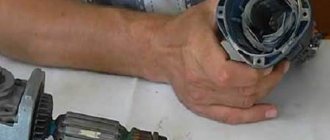
How to restore an electric motor armature
Do-it-yourself collector repair using galvanic extension
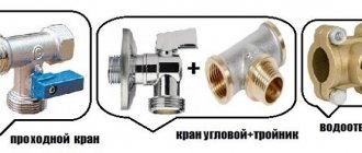
This is what collectors look like that are quite suitable for restoration.
To the left, from the stove, with the lamellas completely burnt out to the insulator, you will have to wind a bare wire with a diameter of about 0.2 mm onto it turn to turn. In the middle of the starter, but already machined for extension. It shows that one lamella has burned out to the base and the rest are extremely worn, but the fastening of the lamellas is not broken, and the wires are welded to the lamellas. Standard diameter 45mm machined to 41mm. On the right, the manifold is also from the stove, quite suitable for restoration without modifications, you just need to clean it.
The anchor for the extension will have to be prepared, since it is not quite ordinary, and an improvised bathtub will have to be made.
Half a plastic bottle is suitable for this. The armature shaft needs to be wrapped with tape, and the end of the commutator should be covered with plasticine so that copper does not accumulate on the ends of the lamellas in vain and so that the electrolyte does not leak between the shaft and the insulator of the commutator; contact of the electrolyte with iron is unacceptable. You need to wind a cork from PVC electrical tape so that it fits tightly into the neck of the bottle from the inside.
At the motor commutator, you need to use a piece of bare wire to connect all the lamellas well together and hang them on the crossbar in a simple jar of electrolyte so that the electrolyte does not touch the hooks, but completely covers the area of wear.
The location of the collector is in the electrolyte, the anode is a tire from a burnt-out starter, its total area should be approximately twice as large as the surface to be built up. The shank is rolled up into a spiral, slightly larger than the diameter of the vessel and, when placed in the vessel, fits tightly to the wall. The minus of the power source is connected to the extension part, the plus to the busbar. The current is selected at the rate of 1.5A per 1 dm2. You can power it from a phone charger, and regulate the current by turning on light bulbs of different power in series. Light bulbs are also needed to protect against possible short circuits in the bathtub.
Electrolyte composition:
- copper sulfate - 200g
- sulfuric acid 1.84 - 40g
- alcohol - 5g
- boiled water - 800ml.
- alcohol can be replaced with triple the amount of vodka.
A day later we get a not entirely attractive appearance of the extended collector.
But after grooving it already looks like this, since copper builds up, although not evenly, but much more than necessary.
Of course, the volume of the bath is small, you can experiment with the composition of the electrolyte, but is this necessary? With this mode, the copper builds up to be very hard, although not evenly. You can cut the grooves between the lamellas with a drill, or simply with a sharpened hacksaw blade, and be sure to check for the absence of short circuits between the plates.
This is what the starter armature, ready for assembly, looks like, its diameter has become 1 mm larger than the standard one, but this does not interfere with anything, but takes longer. You can see by a small chip where the burnt lamella was. On the right is the motor armature ready for winding, the collector is also enlarged by 1 mm. This method can be used to restore almost any collector, unless, of course, it fell apart.
How to rewind an electric motor armature at home
Before starting repairs, prepare the following tools and materials:
- multimeter If it is not there, then you will need a voltage indicator, a megohmmeter and a 12 V light bulb with a power of 30–40 W;
- new winding. The diameter of the core must be identical to the diameter of the old winding;
- soldering iron;
- dielectric cardboard 0.3 mm thick;
- varnish or epoxy resin;
- a skein of thick cotton threads;
- sandpaper.
In order not to do unnecessary work, it is important to correctly identify the cause of equipment failure. To do this, inspect the tool and check whether current is flowing to the collector and the start button using a multimeter or indicator. If everything is in order, then you need to inspect the device from the inside.
Engine diagnostics
Disconnect the tool from the power supply and disassemble the housing. Smell the rotor. If an interturn short circuit occurs, the insulating coating melts and emits a pungent odor.
When there are no external signs of malfunction, it is worth checking the armature lamellas with a multimeter. Switch the device to ohmmeter mode and set the range to 200 ohms. Using two probes, “ring” the adjacent lamellas. A change in resistance indicates a breakdown in the coil.
An ohmmeter can be replaced with a light bulb. Connect the plus and minus terminals to the plug of the device, and place a lamp in the gap. Rotate the armature shaft by hand. If the light blinks, it means that an interturn short circuit has occurred. Is the lamp not on? This means that there is an open circuit or there is no resistance in one of the lamellas.
Replacing the winding and new insulation will prevent the motor from burning out. To extend the life of the electric motor, it is recommended to rewind the rotor at least once every two years.
Instructions: how to rewind the armature winding
Before rewinding, you need to record the main indicators of the engine. Count and write down: the number of armature slots and commutator lamellas. Determine the winding pitch. The most common step 1-6 is when the coil is placed in the initial groove, then in 7 and secured to 1 groove.
Some factory windings use right or left reset. For example, when winding and discarding to the right, the coil moves to the right of the initial groove. So, when the number of armature slots is 12, the winding step is 1–6 and the reset is to the right, the winding is laid in 1 slot, then in 8 and after winding the required number of turns, it is fixed in 2 slots. All this needs to be taken into account. Otherwise, the winding will be laid incorrectly, which will negatively affect the direction of rotation.
Read also: Autonomous heating in a private house with electricity
Rewinding the armature of an electric motor with your own hands will take about 4 hours. To avoid any difficulties during assembly, it is recommended to photograph the original location of the parts during each stage of work:
- Determining the direction and initial winding groove. Find a coil on the winding that is not blocked by others. This is the last reel. If the winding lays to the right, it means that the initial groove is located to the right of the left side of the last coil. This is where you need to start laying the conductor. This way, the rewinding of the armature will be as close as possible to factory conditions. Mark the groove with a marker. With the initial symmetrical winding, the coils are laid in pairs, so there are also two last coils and initial grooves. They are also identified. To make finding grooves easier, pay attention to the image:
- Counting turns. It is necessary to determine the number of turns in the groove (W) and in the winding coil (K). Separate the top coil and count the turns. If necessary, the coil is fired in a burner flame. The nuance of the calculation is that the number of turns of an individual coil in a slot depends on the ratio of the number of collector lamellas to the number of armature slots. For example, the last coil has 60 turns (W), the armature has 12 slots, and the collector lamellas have 36. Then the value of K will be 10 (606), where 6 is the ratio of slots to lamellas, multiplied by 2.
- Preparing the collector. There is no need to remove it. Measure the resistance between the lamellas and the body. To do this, use a megohmmeter or switch the multimeter to the appropriate mode. The minimum resistance is 200 kOhm, the maximum is 0.25 MOhm.
- Dismantling the old conductor. Carefully, without damaging the armature body, remove the old winding.
- Cleaning the grooves and armature body. All carbon deposits and burrs must be sanded with sandpaper.
- Making sleeves for anchors. Cut rectangles from dielectric cardboard to match the size of the armature grooves.
- Rewind. Carefully review all notes made in preparation for the repair. The circuit for rewinding the armature with your own hands must fully correspond to the factory one. The end of the new winding is soldered to the end of the lamella. The wire must be laid from the initial groove, observing the pitch and winding reset.
- Consolidation. Wind several turns of cotton thread tightly onto the winding near the commutator to secure the coils. Synthetic threads cannot be used - they melt.
- Checking circuits. As during diagnostics, check the winding for breaks and interturn short circuits.
- Treatment. If the check does not reveal any malfunctions, then coat the winding with varnish or epoxy resin and dry. To speed up the process, you can put the anchor in a conventional oven for 20 hours at 80 degrees.
Rewind completed. With some skill, repairs do not take much time. If you have changed the winding for the first time, and are not entirely sure of the correct installation of the wire, then you can carry out an additional check.
Angler anchor device
The armature of the angle grinder motor consists of a conductive winding and a magnetic circuit into which the rotation shaft is pressed. It has a drive gear at one end and a commutator with lamellas at the other. The magnetic core consists of grooves and soft plates coated with varnish to insulate them from each other.
Grinder anchor diagram
Two conductors of the armature winding are laid in the grooves according to a special pattern. Each conductor makes up half a turn, the ends of which are connected in pairs on lamellas. The beginning of the first turn and the end of the last are in the same groove, so they are closed to one lamella.
Anchor device
The armature (rotor) together with the stator are included in the design of an asynchronous commutator motor used as an electric motor in angle grinders. If the stator is made in the form of a stationary element, then the rotor just rotates , transmitting torque to the spindle of the angle grinder. Therefore, a shaft with bearing supports at the ends best suits the tasks performed by the rotor.
A metal core with grooves is fixed on the shaft , into which copper wire is laid according to a special winding pattern. The coils thus formed create, together with the stator coils, an electromagnetic field that causes the rotor to rotate.
Scheme of operation of the grinder. Source
A collector is installed on the shaft , which actually gives the name to this type of electric drive. It is a set of copper plates (lamellas) to which the ends of the armature coils are soldered. The stator brushes come into contact with the commutator , which creates a closed electrical circuit into which all the components of the electrical part of the angle grinder are connected.
How to check the angle grinder's anchor for serviceability
Types of armature faults:
- An insulation breakdown to ground is a short circuit of the winding to the metal rotor body. Occurs due to the destruction of insulation.
- Wiring of collector terminals.
- Uneven wear of the commutator.
- visually;
- multimeter;
- light bulb;
- special devices.
If the armature is faulty, the motor overheats, the winding insulation melts, and the turns become short-circuited. The contacts connecting the armature winding to the collector plates are unsoldered. The current supply stops and the motor stops working.
Types of armature diagnostics:
Standard diagnostics
Before taking the diagnostic device, inspect the anchor. It may be damaged. If the wiring is melted, the burnt insulating varnish will leave black marks or a specific smell. You may see bent or crumpled coils or conductive particles, such as solder residue. These particles cause short circuits between turns. The lamellas have curved edges, called cockerels, to connect to the winding.
Due to disruption of these contacts, the lamellas burn out.
Other commutator damage: raised, worn or burnt plates. Graphite from the brushes may accumulate between the lamellas, which also indicates a short circuit.
Bent commutator plates
How to check the anchor on an angle grinder?
Visual inspection rules
Standard diagnostics involve visual analysis of the device. It is necessary to analyze the integrity of the wire and the current supply to the motor commutator. If the power supply is normal, you should inspect the grinder from the inside. Disassembling the device will not be difficult. When disassembling, it is best to photograph the location of the main modules of the device. After disassembly, visually check the anchor for the following properties:
- the anchor must move freely;
- absence of black spots and odor, which may indicate melting of the winding, the insulating varnish of which leaves traces;
- absence of crumpled turns and solder residues, which leads to a short circuit;
- there should be no burnout on the lamella contacts, otherwise you should check the connection between the lamella cockerel and the winding bar;
- no worn or burnt out records;
- the space between the lamellas should not contain graphite residues from brushes.
If a visual inspection does not reveal any deficiencies, then it is necessary to carry out an instrument check. The anchor on an angle grinder can be checked either using a tester or using a regular light bulb.
Inspection using a tester
The multimeter is set to the ohmmeter position. The resistance is set to 200 ohms. The probes are connected to the lamellas located next to each other. If the value on the device is less than 1 ohm, then there is a short circuit. If the value is greater than the average, there may be a break in the turns. If the resistance value is high or there is no value (in the case of using a digital device), a break can also be judged.
There are situations when a break is not detected. Then a test for mass is done. At maximum resistance, one of the probes is placed on the shaft, and the other moves along the plates. If the value is zero, then there is no damage. Then the rotor is checked in the same way with a multimeter. In this case, the probe moves along the lamellas. If it is impossible to check with a tester, a light bulb is used.
Control using a light bulb
In the absence of a device at hand, many are interested in the question of how to check the angle grinder for possible anchor damage. The power supply wire is broken and a light bulb is placed where one wire breaks. Then the shaft rotates. By changing the brightness of the light bulb, you can judge the short circuit between the turns. In the absence of combustion, the following conclusions are possible:
- the location of the brushes does not correspond to the working position due to the activation of the support spring;
- rupture of the supply circuit;
- short circuit or break in the stator winding.
You can ring with an indicator of short-circuited turns and an armature tester. This can be done by an experienced person.
How to check with a multimeter
- Set the resistance to 200 ohms. Connect the probes of the device with two adjacent lamellas. If the resistance is the same between all adjacent plates, then the winding is working. If the resistance is less than 1 ohm and very close to zero, there is a short circuit between the turns. If the resistance is two or more times higher than average, then there is a break in the winding turns. Sometimes when there is a break, the resistance is so great that the device goes off scale. On an analog multimeter, the arrow will go all the way to the right. But digital won’t show anything.
Diagnosis of the armature winding with a multimeter
Video: how the check is carried out
If you don't have a tester, use a 12-volt light bulb with up to 40 watts.
How to check the rotor of an angle grinder using a light bulb
- Take two wires and connect them to the lamp.
- Make a break on the negative wire.
- Apply voltage to the wires. Place the ends of the break against the collector plates and rotate it. If the light bulb lights up without changing brightness, then there is no short circuit.
- Perform a short circuit test to the iron. Connect one wire to the lamellas and the other to the rotor iron. Then with the shaft. If the light is on, it means there is a ground fault. The winding closes to the rotor housing or shaft.
Checking with a short-circuited turns indicator (SCI)
There are anchors where the wires connected to the collector are not visible due to being filled with an opaque compound or due to a bandage. Therefore, it is difficult to determine the commutation on the commutator relative to the slots. An indicator of short-circuited turns will help with this.
This device is small in size and easy to use.
First check the anchor for breaks. Otherwise, the indicator will not be able to detect a short circuit. To do this, use a tester to measure the resistance between two adjacent lamellas. If the resistance is at least twice the average, then there is a break. If there is no break, proceed to the next step.
The resistance regulator allows you to select the sensitivity of the device. It has two lights: red and green. Adjust the regulator so that the red light starts to light. On the indicator body there are two sensors in the form of white dots located at a distance of 3 centimeters from each other. Attach the indicator with the sensors to the winding. Rotate the anchor slowly. If the red light comes on, it means there is a short circuit.
Video: IKZ at work
Diagnostics with an armature testing device (throttle)
The armature testing device determines the presence of an interturn short circuit in the winding. The inductor is a transformer that has only a primary winding and a magnetic gap cut out in the core.
Anchor testing device diagram
When we place the rotor in this gap, its winding begins to act as the secondary winding of a transformer. Turn on the device and place a metal plate, such as a metal ruler or hacksaw blade, on the anchor. If there is an interturn short circuit, the plate will vibrate or be magnetized towards the armature body due to local oversaturation of iron. Rotate the armature around the axis, moving the plate so that it lies on different turns. If there is no short circuit, the plate will move freely along the rotor.
Anchor testing device
Video: How to make a throttle with your own hands and check the anchor
How to repair an anchor at home
A third of screwdriver failures occur due to the anchor. With everyday intensive operation, malfunctions can occur within the first six months, for example, if the brushes are not replaced in a timely manner. With gentle use, the screwdriver will last a year or more.
The anchor can be saved if the balance is not disturbed. If during operation of the device you hear an intermittent hum and there is strong vibration, then this is an imbalance. This anchor must be replaced. And the winding and commutator can be repaired. Small short circuits are eliminated. If a significant part of the winding is damaged, it can be rewound. Worn and badly damaged lamellas should be sharpened, extended or soldered. In addition, you should not undertake anchor repairs if you are unsure of your capabilities. It is better to replace it or take it to a workshop.
Collector groove
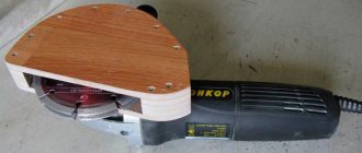
Over time, wear from the brushes forms on the commutator. To get rid of it, you need to:
- Grind the commutator using cutters for longitudinal grinding, that is, through cutters.
Passing straight cutter
Don't forget to clear the rotor of chips to prevent a short circuit.
Video on the topic
How to rewind an anchor
Before disassembling the armature, write down or sketch the direction of the winding. It can be left or right. To determine it correctly, look at the end of the armature from the commutator side. Wear gloves and take sharp wire cutters or a hacksaw. Remove the winding end parts. The collector needs to be cleaned, but it is not necessary to remove it. Carefully, without damaging the slot insulators, knock out the rods of the remaining parts of the winding using a hammer and metal chisel.
Video: Removing the winding
Using a needle file, without damaging the insulator film, remove the remaining impregnation. Count the conductors in the slot. Calculate the number of turns in the section and measure the diameter of the wire. Draw a diagram. Cut cardboard sleeves for insulation and insert them into the grooves.
Video: Winding left and right
After winding, weld the section leads to the collector cocks. Now check the winding with a short circuit tester and indicator. Proceed with impregnation.
Instructions for impregnation (taking into account the speed controller)
- After making sure that there are no problems, send the armature to the electric oven to warm up for better flow of the epoxy resin.
- After warming up, place the anchor on the table at an angle for better spreading over the wires. Apply resin to the frontal area and slowly rotate the anchor. Drip until glue appears on the opposite frontal part.
Impregnation at an angle
Drying the anchor in air before polymerization
At the end of the process, lightly grind the commutator. Balance the anchor using a dynamic balancer and an angle grinder. Now make the final grind on the bearing. It is necessary to clean the grooves between the lamellas and polish the collector. Make a final check for opens and shorts.
The peculiarity of the winding for angle grinders with adjustable speed is that the rotor is wound with a power reserve. Current density affects the number of revolutions. The wire cross-section is too high and the number of turns is too low.
Do-it-yourself Bosch grinder disassembly
For the owner of a power tool, knowledge of its structure and the ability to disassemble it is a mandatory task.
Knowing the procedure for disassembling an angle grinder allows you to independently carry out work such as changing grease, changing bearings and carbon brushes.
To disconnect the gearbox housing pos. 821 from the stator housing pos. 888, you need to disassemble (remove) the body of the grinder handle pos. 24.
This operation must be performed to remove the carbon brushes pos. 810 holding the rotor commutator.
At the second stage, unscrew 4 (four) screws, pos. 61, securing the gearbox and stator housings.
Having pulled out the rotor together with the gearbox, begin disassembling the gearbox.
Repair of a Bosch angle grinder begins with disassembling the gearbox pos. 821. Disassembling the gearbox begins with unscrewing 4 (four) screws, pos. 60. As a rule, the screws are screwed in with sealant at the factory. You will have to make some effort.
Let's note it right away! Low-power Bosch angle grinders use spur gears in the gearbox. Grinders with a power of over 1000 W use helical gears in their gearboxes.
How to remove the driven gear
By removing the gearbox cover, you can get the helical gear assembly, pos. 26.
To remove the gear, you need to use a press or puller. But using a puller is difficult because it requires the use of special thin jaws.
Before removing the helical gear, check the backlash of the gear connection, the integrity of the teeth, and the contact patch.
A bearing, pos. 50, is pressed onto the spindle shaft, pos. 26. If the bearing has a lot of play, is noisy when turning, or the lubricant has dried out, it is preferable to replace it.
To remove the bearing, you need to remove the gear, retaining ring and dismantle the bearing. If, when dismantling the rotor shaft assembly, the bearing remains in the gearbox housing, dismantling the bearing is carried out using a hammer and a soft tool.
Repair: Elimination of insulation breakdown
If the insulation breakdown was small and you found it, you need to clean the area of carbon deposits and check the resistance. If its value is normal, insulate the wires with asbestos. Apply quick-drying “Super Moment” type glue on top. It will seep through the asbestos and insulate the wire well.
If you still haven’t found the location of the insulation breakdown, then try carefully soaking the winding with impregnating electrical insulating varnish. Punched and unpierced insulation will be saturated with this varnish and become stronger. Dry the anchor in a gas oven at about 150 degrees. If this does not help, try rewinding the winding or changing the armature.
Soldering the collector plates
The slats are mounted on a plastic base. They can be erased to the very base. Only the edges remain that the brushes cannot reach.
Such a collector can be restored by soldering.
- Cut the required number of lamellas to size from a copper pipe or plate.
- After you have stripped the armature of copper residues, solder it with regular tin and soldering acid.
- When all the lamellas are soldered, sand and polish. If you don't have a lathe, use a drill or screwdriver. Insert the armature shaft into the chuck. First, sand with a file. Then polish with grit sandpaper. Don't forget to clean the grooves between the slats and measure the resistance.
- There are lamellas that are not completely damaged. To restore them, more thorough preparation is necessary. Lightly grind the commutator to clean the plates.
Damaged commutator plate
Expanding the space with a drill
Preparing the lamella in the groove
If the collector has been completely worn out, then after soldering it will last no more than a month of active use. And plates that are not completely damaged after such repairs can withstand several replacements of brushes and do not become desoldered.
Galvanic extension of collector plates
Reduced copper is very hard. The service life of the collector is like new. Galvanic extension can be used to restore both a completely worn out collector and partially damaged plates.
Features of the asynchronous motor of the angle grinder
Almost all electrical appliances used in everyday life use an asynchronous electric motor. An important advantage of this type of motor is that when the load on it changes, the speed does not change. This means that if, for example, you cut stone for a long time and without stopping with a household grinder, there will be no noticeable external signs of engine overload. The disk rotation speed will be constant, the sound will be monophonic. Only the temperature will change, but this may not be noticed if your hands are wearing gloves.
If you are not careful, an advantage can turn into a disadvantage. Asynchronous motors are very sensitive to overheating; a significant increase in operating temperature entails melting of the insulation on the rotor windings. At first, the motor will work intermittently, and then - when an interturn short circuit occurs - the motor will stop completely. If you overheat the grinder's engine several times, it is most likely that the anchor will melt. In addition, the high temperature causes the contacts connecting the wires of the primary winding to the collector to become unsoldered, which leads to an interruption in the supply of electric current.
How to determine if an angle grinder's armature is faulty
Signs of a broken armature angle grinder are: increased sparking of the brushes on the motor commutator, vibration of the motor at low speeds, rotation of the working shaft in different directions. If such symptoms are present, you should stop using the tool - this is dangerous. Suspicions can be easily verified using simple tests.
Visual inspection from outside
Troubleshooting should begin with a visual inspection of the angle grinder:
- Carry out a general inspection of the instrument.
- Pay attention to the integrity of the power cord and the presence of voltage in the outlet.
- Using a voltage indicator, make sure that current is flowing to the motor commutator and the start button.
Inspection of the device from the inside
If everything is in order with the power supply, but the angle grinder does not work, you will have to open the case to gain access to the motor. As a rule, disassembly is not difficult. But you need to follow simple rules that will help you avoid troubles during reassembly:
- Be sure to disconnect the device from the mains before disassembling.
- Remove the working disk and protective cover from the spindle.
- Open the case in a well-lit place, on a clean table surface.
- Remember the location of all parts and assemblies before disassembling. It is recommended to sketch or photograph the internal structure of the device.
- Place screws and fastening screws in a separate place so that they do not get lost.
It is best to inspect the engine under bright lighting so that all small parts are clearly visible. The armature should rotate freely around its axis; properly functioning bearings should not make any sound during operation. There should be no traces of melted wiring on the armature, the circuit windings should be intact, without breaks. You can smell the rotor. When there is an interturn short circuit, the insulating varnish burns and emits a persistent specific odor. But such a diagnosis requires some experience.
Continuity testing of circuits with a tester
If a visual inspection does not give clear results, it is recommended to continue the examination using a multimeter. Having set the mode switch to the ohmmeter position (200 Ohm range), you need to “ring” two adjacent armature lamellas with two probes. If the resistance on all turns is the same, this means that the windings are working properly. If on some pairs the tester shows a different resistance or an open circuit, there is a malfunction in this coil.
A wire break can occur between the winding and the core. You should carefully examine the junction of the coils with the collector lamellas in the lower part of the armature, and visually check the soldering of the contacts.
Checking contacts with a light bulb
If you don’t have a tester, you can get out of the situation using a simple 12-volt light bulb. The power can be any, optimally 30–40 W. The voltage from the 12 volt battery must be applied to the plug of the angle grinder by inserting a light bulb into the gap in one wire. If the armature is working properly, if you rotate the spindle by hand, the light should light without changing brightness. If the heat changes, this is a sure sign of an interturn short circuit.
If the light does not light, this may indicate the following:
- The brushes may become stuck in the non-working position. The retaining spring has worked.
- There has been a break in the supply circuit.
- There is a short circuit or break in the stator winding.
There are other diagnostic methods, but they require more sophisticated equipment, which is not usually used at home. An experienced technician will determine the breakdown with a high degree of accuracy using a “punch” or a simple transformer with a cut toroidal core and one primary winding.
How to check the rotor for serviceability
Multimeter Zubr. Photo 220Volt
The scope of repair work can be determined by competent diagnosis of rotor damage. The specifics of the formation of defects, which most often appear when the angle grinder overheats during prolonged operation at high loads, allows you to determine them visually . Burnt electrical insulation leaves charring marks in places where the coils are damaged or on the commutator lamellas. Broken wires and swollen collector lamellas can also be seen after a careful external inspection.
If a visual inspection fails to identify malfunctions or doubts arise, diagnostics are carried out by checking the electrical circuit using instruments. Here, a breakdown to the housing or a wire break can be detected with a multimeter , and an interturn short circuit with an indicator of short-circuited turns or on a special device for checking the presence of a short circuit of the turns.
In what cases can you save an anchor and restore it yourself?
If damage to the armature is determined with guaranteed accuracy, the part must be removed from the electric motor. Disassembling the motor must be done with special care, after removing the brushes and disconnecting the power terminals. The rotor is removed along with the support bearings and the motor cooling impeller; they form a single whole with it.
If most of the wiring in the armature is damaged and the balancing is disrupted as a result of overheating, it is better to replace it entirely. An imbalance is indicated by increased vibration and an uneven hum when the mechanism operates.
How to rewind an anchor - step-by-step instructions
If the balancing of the armature is not disturbed, and the problem is only in damaged windings, then such an armature can be restored independently by rewinding the coils. Rewinding a rotor at home requires a lot of patience and accuracy.
The technician must have skills in working with a soldering iron and instruments for diagnosing electrical circuits. If you are unsure of your abilities, it is better to take the engine to a workshop for repairs or replace the entire armature yourself.
To rewind the anchor yourself you will need:
- wire for a new winding. A copper core with a diameter exactly matching the old conductor is used;
- dielectric paper for insulating the winding from the core;
- varnish for filling coils;
- soldering iron with tin-lead solder and rosin.
Before rewinding, it is important to count the number of turns of wire in the winding and wind the same amount of new conductor onto the coils.
The rewinding process consists of the following steps:
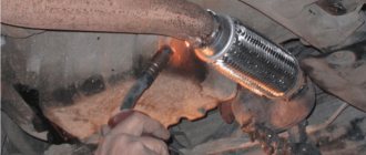
- Dismantling old windings. They must be carefully removed without damaging the metal body of the armature. If any burrs or damage are found on the body, they must be smoothed out with a file or sanded with emery. Sometimes, to completely clean the body of slag, craftsmen prefer to burn it with a torch.
- Preparing the collector for connecting a new wire. There is no need to remove the manifold. You should inspect the lamellas and measure the resistance of the contacts in relation to the housing with a megger or multimeter. It should be no more than 0.25 MOhm.
- Removing old wiring on the manifold. Carefully remove the remaining wires and cut grooves in the contacts. In the future, the ends of the coil wires will be inserted into the grooves.
- Installation of sleeves for anchors. The sleeves are made of dielectric material 0.3 mm thick, for example, electrical cardboard. Cut a certain number of sleeves and insert them into the grooves of the cleaned anchor.
- Rewinding reels. The end of the new conductor is soldered to the end of the lamella and wound in successive circular movements, counterclockwise. This laying is called “laying to the right.” Winding Repeat for all coils. Near the collector, tie the wires together with a thick thread of cotton fabric (it is prohibited to use nylon, as it melts when heated).
- Checking the winding quality. After laying all the windings, check with a multimeter for the absence of interturn short circuits and possible breaks.
- Finishing processing. Treat the finished coil with varnish or epoxy resin to secure the winding. In factory conditions, the impregnation is dried in special ovens. You can do this at home in the oven. As an option, use quick-drying varnishes for impregnation, applying the coating in several layers.
Rewinding the armature
Anchors for angle grinders can be rewound at home. To do this, you need to have certain skills when working with a soldering iron. To rewind the armature with your own hands, you will need:
- a wire with a copper core that matches the previous conductor;
- dielectric paper to insulate the winding;
- varnish for filling coils;
- soldering iron
Before starting to wind the armature, it is important to count the number of turns in the old winding and do the same number on the new coil.
Rewind scheme:
- removing previous windings - try not to damage the surface of the housing. If damage occurs, sand with sandpaper or a file;
- inspection of the collector - the resistance value of the lamella contacts in comparison with the shell should not exceed 0.25 Mohm;
- cleaning the collector from old wires - developing grooves for inserting the ends of new wires;
- placement of sleeves - they are made of non-conducting material, for example, electrical cardboard. Their size is 0.3 mm;
- rewinding the coils - the end of the new wire is attached to the end of the lamella. Rewind in a counterclockwise direction. Secure the wires near the collector with cotton thread;
- control for the absence of short circuits - measure the resistance with a tester;
- applying varnish or epoxy to secure the winding - dry it in the oven or use products that dry quickly.
If it is not possible to perform such actions, then you can replace the angle grinder’s anchor.
Replacing the anchor yourself at home
Practice shows that if you decide to replace the armature of an angle grinder, then it is best to change it together with the support bearings and the engine cooling impeller.
To replace you will need:
- New angle grinder anchor. Must match your model. Interchange with other models is not permitted.
- Screwdrivers, wrenches.
- A soft brush and cloth for wiping the mechanism.
How to remove an anchor
Replacing the anchor begins with disassembling the angle grinder. The following steps are performed:
- Use a screwdriver to unscrew the brush units on both sides. The brushes are removed.
Video: replacing bearings on an angle grinder
How to put an anchor in place
To install a new angle grinder anchor in place, you should take a new part, and then assemble the tool in the reverse order. The sequence of actions is as follows:
- A fixation disk is installed on the armature shaft.
- The bearing is installed using the pressing method.
- The small gear is fitted and secured with a retaining ring.
- The anchor is inserted into the gearbox housing, and the docking holes are aligned.
- The gearbox mounting bolts are tightened.
- The anchor with the gearbox is inserted into the body of the angle grinder and fixed.
- The brushes are deposited in their places and closed with lids.
After completing these steps, the grinder is ready for work. The anchor has been replaced.
Video: how to check an angle grinder
An ancient Sufi wisdom says: “A smart person is one who is able to come out of a difficult situation with dignity. But the one who does not find himself in such a situation is wise.” By following the rules for operating household appliances and preventing the motor from overheating, you can avoid breakdowns and troubles in the operation of the angle grinder. Keeping and storing the tool clean and dry will prevent its mechanisms from contamination and oxidation of current-carrying elements. Timely maintenance of the tool is guaranteed to eliminate unpleasant surprises during operation.
Checking and repairing the angle grinder's anchor with your own hands 1
Almost all electrical appliances used in everyday life use an asynchronous electric motor. An important advantage of this type of motor is that when the load on it changes, the speed does not change.
This means that if, for example, you cut stone for a long time and without stopping with a household grinder, there will be no noticeable external signs of engine overload. The disk rotation speed will be constant, the sound will be monophonic.
Only the temperature will change, but this may not be noticed if your hands are wearing gloves.
The induction motor commutator is sensitive to overheating
If you are not careful, an advantage can turn into a disadvantage. Asynchronous motors are very sensitive to overheating; a significant increase in operating temperature entails melting of the insulation on the rotor windings.
At first, the motor will work intermittently, and then - when an interturn short circuit occurs - the motor will stop completely. If you overheat the grinder's engine several times, it is most likely that the anchor will melt.
In addition, the high temperature causes the contacts connecting the wires of the primary winding to the collector to become unsoldered, which leads to an interruption in the supply of electric current.
How to determine if an angle grinder's armature is faulty
Signs of a broken armature angle grinder are: increased sparking of the brushes on the motor commutator, vibration of the motor at low speeds, rotation of the working shaft in different directions. If such symptoms are present, you should stop using the tool - this is dangerous. Suspicions can be easily verified using simple tests.
Visual inspection from outside
Troubleshooting should begin with a visual inspection of the angle grinder:
- Carry out a general inspection of the instrument.
- Pay attention to the integrity of the power cord and the presence of voltage in the outlet.
- Using a voltage indicator, make sure that current is flowing to the motor commutator and the start button.
The indicator checks the integrity of the electrical circuit
Inspection of the device from the inside
If everything is in order with the power supply, but the angle grinder does not work, you will have to open the case to gain access to the motor. As a rule, disassembly is not difficult. But you need to follow simple rules that will help you avoid troubles during reassembly:
- Be sure to disconnect the device from the mains before disassembling.
- Remove the working disk and protective cover from the spindle.
- Open the case in a well-lit place, on a clean table surface.
- Remember the location of all parts and assemblies before disassembling. It is recommended to sketch or photograph the internal structure of the device.
- Place screws and fastening screws in a separate place so that they do not get lost.
It is best to inspect the engine under bright lighting so that all small parts are clearly visible. The armature should rotate freely around its axis; properly functioning bearings should not make any sound during operation.
There should be no traces of melted wiring on the armature, the circuit windings should be intact, without breaks. You can smell the rotor. When there is an interturn short circuit, the insulating varnish burns and emits a persistent specific odor.
But such a diagnosis requires some experience.
Continuity testing of circuits with a tester
If a visual inspection does not give clear results, it is recommended to continue the examination using a multimeter.
Having set the mode switch to the ohmmeter position (200 Ohm range), you need to “ring” two adjacent armature lamellas with two probes. If the resistance on all turns is the same, this means that the windings are working properly.
If on some pairs the tester shows a different resistance or an open circuit, there is a malfunction in this coil.
Using a multimeter in resistance measurement mode, check the integrity of the coils
A wire break can occur between the winding and the core. You should carefully examine the junction of the coils with the collector lamellas in the lower part of the armature, and visually check the soldering of the contacts.
Checking contacts with a light bulb
If you don’t have a tester, you can get out of the situation using a simple 12-volt light bulb. The power can be any, optimally 30–40 W.
The voltage from the 12 volt battery must be applied to the plug of the angle grinder by inserting a light bulb into the gap in one wire. If the armature is working properly, if you rotate the spindle by hand, the light should light without changing brightness.
If the heat changes, this is a sure sign of an interturn short circuit.
If the light does not light, this may indicate the following:
- The brushes may become stuck in the non-working position. The retaining spring has worked.
- There has been a break in the supply circuit.
- There is a short circuit or break in the stator winding.
There are other diagnostic methods, but they require more sophisticated equipment, which is not usually used at home. An experienced technician will determine the breakdown with a high degree of accuracy using a “punch” or a simple transformer with a cut toroidal core and one primary winding.
In what cases can you save an anchor and restore it yourself?
If damage to the armature is determined with guaranteed accuracy, the part must be removed from the electric motor. Disassembling the motor must be done with special care, after removing the brushes and disconnecting the power terminals. The rotor is removed along with the support bearings and the motor cooling impeller; they form a single whole with it.
Diagram of an angle grinder's anchor device
If most of the wiring in the armature is damaged and the balancing is disrupted as a result of overheating, it is better to replace it entirely. An imbalance is indicated by increased vibration and an uneven hum when the mechanism operates.
How to rewind an anchor - step-by-step instructions
If the balancing of the armature is not disturbed, and the problem is only in damaged windings, then such an armature can be restored independently by rewinding the coils. Rewinding a rotor at home requires a lot of patience and accuracy.
The technician must have skills in working with a soldering iron and instruments for diagnosing electrical circuits. If you are unsure of your abilities, it is better to take the engine to a workshop for repairs or replace the entire armature yourself.
To rewind the anchor yourself you will need:
- wire for a new winding. A copper core with a diameter exactly matching the old conductor is used;
- dielectric paper for insulating the winding from the core;
- varnish for filling coils;
- soldering iron with tin-lead solder and rosin.
Before rewinding, it is important to count the number of turns of wire in the winding and wind the same amount of new conductor onto the coils.
The rewinding process consists of the following steps:
- Dismantling old windings. They must be carefully removed without damaging the metal body of the armature. If any burrs or damage are found on the body, they must be smoothed out with a file or sanded with emery. Sometimes, to completely clean the body of slag, craftsmen prefer to burn it with a torch.
- Preparing the collector for connecting a new wire. There is no need to remove the manifold. You should inspect the lamellas and measure the resistance of the contacts in relation to the housing with a megger or multimeter. It should be no more than 0.25 MOhm.
- Removing old wiring on the manifold. Carefully remove the remaining wires and cut grooves in the contacts. In the future, the ends of the coil wires will be inserted into the grooves.
- Installation of sleeves for anchors. The sleeves are made of dielectric material 0.3 mm thick, for example, electrical cardboard. Cut a certain number of sleeves and insert them into the grooves of the cleaned anchor.
- Rewinding reels. The end of the new conductor is soldered to the end of the lamella and wound in successive circular movements, counterclockwise. This laying is called “laying to the right.” Winding Repeat for all coils. Near the collector, tie the wires together with a thick thread of cotton fabric (it is prohibited to use nylon, as it melts when heated).
- Checking the winding quality. After laying all the windings, check with a multimeter for the absence of interturn short circuits and possible breaks.
- Finishing processing. Treat the finished coil with varnish or epoxy resin to secure the winding. In factory conditions, the impregnation is dried in special ovens. You can do this at home in the oven. As an option, use quick-drying varnishes for impregnation, applying the coating in several layers.
Replacing the anchor yourself at home
Practice shows that if you decide to replace the armature of an angle grinder, then it is best to change it together with the support bearings and the engine cooling impeller.
To replace you will need:
- New angle grinder anchor. Must match your model. Interchange with other models is not permitted.
- Screwdrivers, wrenches.
- A soft brush and cloth for wiping the mechanism.
How to remove an anchor
Replacing the anchor begins with disassembling the angle grinder. The following steps are performed:
- Use a screwdriver to unscrew the brush units on both sides. The brushes are removed. To remove, you will need a wide flat-head screwdriver
- Unscrew the 4 screws securing the gearbox housing. Remove the housing carefully
- Carefully open and remove the gearbox cover to gain access to the inside of the gear mechanism. To disassemble the gearbox you will need a puller
- The retaining ring securing the small gear to the armature is removed.
- The armature retainer is released from its fastening and the armature is removed along with the small gear and bearing.
- The gear, bearing and armature fixing disk are removed and wiped with a rag. The bearing is removed with a special puller. The puller is activated by rotating the thrust screw
How to put an anchor in place
To install a new angle grinder anchor in place, you should take a new part, and then assemble the tool in the reverse order. The sequence of actions is as follows:
- A fixation disk is installed on the armature shaft.
- The bearing is installed using the pressing method.
- The small gear is fitted and secured with a retaining ring.
- The anchor is inserted into the gearbox housing, and the docking holes are aligned.
- The gearbox mounting bolts are tightened.
- The anchor with the gearbox is inserted into the body of the angle grinder and fixed.
- The brushes are deposited in their places and closed with lids.
After completing these steps, the grinder is ready for work. The anchor has been replaced.
: how to check an angle grinder
An ancient Sufi wisdom says: “A smart person is one who is able to come out of a difficult situation with dignity. But the one who does not find himself in such a situation is wise.
» By following the rules for operating household appliances and preventing the motor from overheating, you can avoid breakdowns and troubles in the operation of the angle grinder. and keeping the tool clean and dry will prevent its mechanisms from contamination and oxidation of current-carrying elements.
Timely maintenance of the tool is guaranteed to eliminate unpleasant surprises during operation.
Source: https://100uslug.com/proverka-i-remont-yakorya-bolgarki-svoimi-rukami/
Checking the continuity of the angle grinder's anchor with your own hands
Rotor for INTERSKOL USHM-2300M, HAMMER. Photo 220Volt
When an angle grinder fails, diagnostics are performed to identify the causes . One of them may be a breakdown of the armature (rotor) of the electric drive. check the serviceability/failure of this rotating assembly yourself . It is necessary to have in your arsenal only simple devices for testing the electrical circuit.
Device
To correctly diagnose armature faults, it is important to know the device and the principle of its operation . The main elements of the armature are a round core, consisting of a set of electrical steel plates and a winding wound into its grooves in a certain way. Two armature windings are placed in each of the grooves according to a special pattern . The first and last turns of one of the windings are in the same groove and are closed to one lamella.
Rotor for Makita angle grinder 9069 MAX. Photo 220Volt
The core is pressed onto the rotor , which rotates under the influence of forces arising in the electromagnetic field formed by the armature windings and the stator coils working in tandem with it. In grinders, the anchor is an assembly unit with a drive gear located at one end of the shaft, and a commutator unit at the opposite end.
Causes of malfunctions
The causes of rotor failure may be improper operation of the power tool, which is represented by the following factors:
- the permissible time of continuous operation has been exceeded, which is one of the main reasons for the failure of household angle grinders;
- carrying out work in aggressive environments with the presence of sand, moisture, abrasive dust and other similar materials;
- work under conditions exceeding the permissible load;
- some mechanical faults affect the imbalance of the rotating rotor, which ultimately affects the normal functioning of the rotor electrical circuit;
- instability of the mains voltage while working with a power tool.
Serviceable rotor for Bosch angle grinder GWS6-100/GWS 850 MAX. Photo 220Volt
The operation of a power tool associated with the action of these factors leads to the following malfunctions :
- breakage of coil conductors;
- short circuit between turns due to burnt insulation;
- the insulation loses its properties, which can cause breakdown of the winding to the core body;
- violation of collector contacts;
- Particles of burnt insulating varnish or melted solder that get into the gaps that come into contact with the rotating rotor can cause mechanical damage to the elements of the angle grinder: cracks, chips, deep scratches.
- The collector lamellas wear out unevenly and carbon deposits form on them due to a short circuit.
This mainly happens when the grinder's commutator engine operates for a long time without a rest break. The winding insulation from heating loses its characteristics and melts, which leads to a short circuit of the turns. The contacts connecting the armature winding to the commutator lamellas can become unsoldered, the electric current is interrupted and the electric drive stops.
Armature fault
There are criteria on the basis of which we can conclude that the anchor requires repair:
- the number of sparks emanating from the brushes on the engine commutator increases;
- vibration appears at low speed;
- the working shaft begins to move in different positions.
The presence of these signs indicates a broken anchor. Subsequent use may be dangerous.
The following damage to the anchor is known:
- breakage of electrical conductors;
- short circuit between turns;
- insulation failure, which leads to a short circuit of the winding to the metal surface of the rotor;
- soldering the ends of the collector;
- Uneven commutator wear.
As a result of these malfunctions, the engine gradually stops working. To find out the reason for the failure of the angle grinder, diagnostics should be carried out. It can be carried out visually or using appropriate instruments.
How to check the serviceability and ring the rotor of an angle grinder at home, video
At home, there are the following methods for diagnosing an anchor:
- visual inspection;
- using a multimeter;
- a light bulb and two wires connected to it;
- devices specially designed for checking the integrity of windings (short circuit indicator, armature testing device and others).
For more information about the types of diagnostics, see the information below, where there is a video.
Visual inspection
Even if you have a full arsenal of instruments for testing the armature electrical circuit, never neglect a visual inspection - the mandatory first step of the entire diagnostic process.
A careful look will find signs by which a user who knows the design and principles of operation of the rotor will determine the nature of the malfunction. Charred marks and the presence of a specific odor cause burnt insulation and ultimately damage to the winding wires. You should pay attention to crumpled or swollen coils , which may indicate the presence of breaks in a given location. solder particles on , which can cause a short circuit.
Violations in the contacts of the windings with the collector can be detected by burnt out lamellas . Damage to the collector itself is visually diagnosed - raised, worn or burnt plates.
Tester, multimeter
The device multimeter or its other name is a tester for measuring electrical parameters: current, voltage, resistance - can be used to search for breaks in winding wires or breakdowns in the core body.
In the following video, the author offers a diagnostic option from simple to complex. Using a multimeter, the stator is first tested. It is much easier to check it than the rotor. If there are no breaks on the stator and no breakdowns of the winding to the housing, then we can conclude that the armature is faulty. Next, you should diagnose it in more detail, determining the exact type of defect and determining the method of elimination. A continuity test is carried out with a multimeter in the “resistance test” mode with the minimum measurement scale set (up to 200 Ohms).
This video, like the other, shows the process of determining winding breaks, which is really quite labor-intensive, since measurements are taken between each pair of lamellas along the entire contour of the collector. In this case, on an armature that does not have breaks in the windings, all multimeter readings should not differ from each other within 0.1 Ohm. It is much easier to check the breakdown of the windings on the body by placing one probe on the core body and the other on the collector plates. The multimeter scale should not respond with any readings.
It is impossible to determine the interturn short circuit with a multimeter. Other devices are used here.
Interturn short circuit indicator
In the following video, the author tests a device for determining the interturn circuit (IMC) of his own making. The principle of its operation is based on the interaction of electromagnetic fields created by the coils of the IMZ device and the windings of the armature or stator. In the presence of an interturn short circuit, the parameters of the magnetic field of the device change, which is recorded by a light indication - the red light comes on, and if there is no short circuit, the green light lights up.
A light bulb
If you don’t have a multimeter, you can test the electrical circuit of the rotor using a 12 V light bulb. First , connect two wires to the light bulb itself. The power source is a regular battery, to the ends of which you should connect the ends of the break of one of the wires connected to the light bulb. Such an amateur “device” is used instead of a multimeter, where the ends of the wires are applied to the lamellas without touching each other. Carefully rotate the armature to monitor the brightness of the light bulb. If it is constantly on without blinking, then there are no breaks in the winding.
Breakdown of the winding to the core body is checked by connecting one of the ends to the collector and the other to the core or shaft. If the light comes on, it means there is a breakdown of the winding to the housing.
Throttle
The presence of an interturn short circuit in the rotor can be determined using a device for testing armatures. It is a transformer with one primary winding ; in fact, it is a wire wound on a ferromagnetic core. At the same time, it has a triangle cutout in it, in which the rotor under test can be stably positioned. Its winding begins to work as a secondary coil of a transformer.
In the presence of an interturn short circuit, the parameters of the rotor magnetic field have greater intensity; a metal strip placed on the surface of the core will vibrate and, when magnetized, will be attracted to the core body. The plate will move freely on the rotor core body if it has normal windings without defects.
How to check the stator winding of an angle grinder at home in different ways
There are a large number of different electrical devices that can be used to diagnose the stator. However, at home, a limited number of technical means are used. Some are presented in the following videos.
Checking the armature/rotor and stator with a multimeter/tester
In the following video, a multimeter, or more commonly called a tester, is used as a tool for diagnosing the rotor and stator of an electric drive. Used to measure various electrical parameters: resistance, current, voltage. To determine faults in the form of broken wires or breakdown of the winding on the housing, the “ohmmeter” mode is used, that is, a certain resistance value is set, which is comparable to that present in the circuit being tested. In this case, with a limit of 200 Ohms.
A breakdown of the stator to the housing is determined by applying indicator probes to its housing and one of the ends of the winding. The presence of any resistance value on the indicator indicates the presence of a defect in the form of a breakdown of the winding to the housing. When diagnosing a winding break, the device indicator will not show anything when the probes are aligned with the winding terminals.
More complex manipulations should be carried out when checking the rotor windings of an electric drive. A winding break can occur in any connection with a single commutator lamella. Therefore, it is necessary to check the resistance between all lamellas of the collector by applying indicator probes to them one by one. In the absence of a break, the resistance will have the same small value in all cases. Any deviations indicate the presence of a break. Breakdown of the winding to the housing is checked with probes when they come into contact with the commutator and the “iron” from a set of electrical steel sheets. The indicator scale should not react to this action.
However, it is impossible to determine the turn-to-turn short circuit with a multimeter. A device called a short-circuited turn indicator (SCI) is used here. More details about it in the information below.
For interturn short circuit, indicator
The operating principle of the device for determining interturn short circuits is shown in the following video. The device induces a magnetic field in the winding being tested. If there are short-circuited turns in the winding, the short circuit current causes increased resistance to the electromagnetic field generated by the device. By adjusting the IKZ, a setting is made, upon reaching which a light signal is triggered (the indicator light changes color from green to red) or a sound is heard. In addition to the main application, the author shows a method for determining where the winding wires are connected to the commutator lamellas, in the absence of visually visible contacts.
Makita, without instruments
In one of the Makita models in the following video, smoke began to appear during operation, which is a sure sign of a burnt out rotor or stator. To determine the reasons, the author performed a complete disassembly of the angle grinder, which made it possible to perform a good external inspection of the components of the angle grinder suspected of malfunctioning. While no signs of smoke damage were found on the rotor, several places of burnt electrical insulating varnish were clearly visible on the stator.
Important: after a visual inspection, it is necessary to once again check with instruments the unit on which no external defects were found. So, for example, in this case, a multimeter detected breaks in the winding on the rotor. By the way, an external inspection of the stator turned out to be sufficient, since the multimeter could not detect a defect in the form of an interturn short circuit
By the way, an external inspection of the stator was sufficient, since the multimeter could not detect a defect in the form of an interturn short circuit.
Automatic multimeter: performs measurements quickly and efficiently
The multimeter, which is presented in the following video, is easy to use and allows you to take readings without unnecessary fuss, when the measured values “jump” in a device that does not have this option. A method for determining the measurement error associated with the resistance of indicator probes is shown. The approximate value of the winding resistance where there are no faults is given.
Repair, replacement, rewind
After diagnosing and determining the types of rotor faults, a decision on repair methods follows . It is possible to do the repair yourself, which will involve rewinding the armature yourself. If this option seems labor-intensive and complicated, you can follow a simplified scheme and replace the burnt out rotor with a new one that matches the model of the angle grinder. The simplest, but also expensive option is to contact a special service department.
When deciding to repair an anchor with your own hands, the information available in the links “How to remove an anchor from an angle grinder”, “Replacing and repairing an angle grinder’s anchor”, “Rewinding an angle grinder’s anchor with your own hands” will help.
Possible malfunctions of the commutator motor
Sometimes even people familiar with the structure of the mechanism have little idea how to check a commutator motor. Below we will talk about all possible malfunctions and ways to identify and eliminate them.
- Broken contacts. This is indicated by active sparking.
- Interturn short circuit (short circuit of windings in the collector). It also causes sparking.
- Wear of the brush-collector unit. At the same time, it turns black and sparking appears. Usually the problem is solved by replacing old elements with new ones. To remove the assembly, move the lock and unscrew the mounting bolt (depending on the engine model).
- Darkening of the contact part of the collector. Often it is enough to clean it with fine sandpaper.
- Formation of a groove at the point of contact of the brushes with the commutator. It is necessary to perform the grooving of the unit on the machine.
- Bearing wear. This malfunction can be determined by increased vibration of the housing during engine operation and beating of the cartridge. In this case, bearing replacement is required.
- The armature touches the stator. Sometimes replacing the armature is enough, but in some cases you will have to replace both the armature and the stator.
- Control failure on the microcontroller. Installing a new microcontroller is the optimal solution to the problem.
- Burnout or breakage of windings. Pay attention to their color and integrity. Blackening of the entire winding body or part thereof indicates burnout; a break is easily determined by visual inspection. In this case, they need to be replaced or rewinded.
- Graphite dust in the space between the lamellas. Your appliance just needs cleaning.
- Burnout of wire insulation. A characteristic odor will indicate this problem.
Read also: Boiler piping with natural circulation
In all of the above cases, restoring the electric motor manifold with your own hands is quite possible if you have the necessary spare parts and tools. Only if you do not have experience in rewinding windings, it is better to contact the appropriate service. After troubleshooting, reconnect all parts in reverse order.