Coordinate table for drilling machine
The design of the drive in the coordinate table is mechanical. It is the simplest and most affordable option.
First we prepare two rods (which can be obtained from car parts) and two bushings, as well as a screw and nuts.
At the next stage, take a corner, cut off two pieces, and drill holes in them into which two rods with a screw are inserted. A metal plate is welded onto the bushings.
Next we move on to making another carriage with guides. Now we will be able to move the table in two coordinates, and this design is convenient.
Flywheels are attached to the lead screws. They are sold in stores, but you can make them in your workshop.
After this, a pair of platforms are connected with a perpendicular arrangement to one another. Next, this very table is made. We do this using steel plates.
The final stage is to assemble and paint all the parts.
Watch the video for a more detailed study
Algorithm for making a coordinate table with your own hands for beginners
For proper operation of drilling equipment, several additional devices are needed that will facilitate the work of the master and increase his efficiency. In particular, a special working surface is needed to equip the machine, which increases the productivity of the device. Making a good coordinate table with your own hands is not so easy, but it is possible. An experienced specialist will assemble it, saving a lot of money on the purchase of factory equipment.
Manufacturing of load-bearing elements
The materials for making the table frame are:
- cast iron;
- metal;
- aluminum.
The latter material is used for circuits with light loads and low torque forces. This option is acceptable when drilling wood or plastic.
Drawn aluminum frame profile, mounted on threaded connections. This creates a solid foundation. Advantages of the material:
- low weight;
- accessibility;
- ease of installation.
Many companies produce ready-made kits for assembling tables with your own hands.
Drilling machine with cross table
Cast base structures are often cast iron. Their weight is significant, but the forces they can withstand are quite high. Such tables are used for large production volumes. Installation is carried out on the foundation, permanently.
A welded frame is the best option for both production facilities and home use. The main thing is to reduce the welding stresses of the metal by releasing it when welding with your own hands. Otherwise, when the engine picks up speed, cracks may appear in the frame.
For drilling machines, two table technological schemes are used:
- cross;
- portal
Drilling machine with gantry table
The first is used for bulk workpieces. It makes it possible to carry out other manipulations on the fixed workpiece. With this arrangement, access to the part is provided from three sides.
The portal pattern is used when drilling flat products. It is easier to manufacture and has increased processing accuracy.
Advantages and disadvantages of self-production
A coordinate table is an additional structure to a milling, drilling metal or woodworking machine. Thanks to it, you can increase equipment productivity by reducing the labor intensity of the parts processing process. The workpiece is simply fixed on the working surface and can move smoothly along a given path.
Homemade coordinate tables have the following advantages:
- small dimensions;
- simple design form;
- controlled mechanically;
- used in handicraft production.
Their main advantage is saving money. Making such a design from scratch will cost much less than buying a factory-made manipulator. Of course, there are a number of difficulties when making it yourself. A suitable drawing is needed, according to which the required trajectory of the workpiece will be set. If there is no someone else’s experience, then you will have to create it yourself, but any error when drawing the diagram will make itself felt during work. In addition, a homemade table is only suitable for small-scale production, since the simplest homemade mechanisms wear out much faster than factory ones.
For mass production of parts and their processing, only a factory model of a coordinate table is suitable.
Scope of application and benefits
Rotary tables are widely used on machines for various purposes - both on automatic lines for mass production of parts, and in individual installations.
These are milling, vertical drilling machines, forging hammers, presses and other equipment where it is necessary to ensure rapid movement of the workpiece relative to the working body. Rotary tables are also used in welding operations to perform relief and spot welding. The main advantage of a rotary table is the ability to process parts in different planes. Thus, for milling machines, in addition to moving the workpiece in three main directions (longitudinal, transverse and vertical), the rotary table can provide rotation of the part in the vertical and horizontal planes. The table ensures movement of the workpiece in various coordinates, fixing it at the required angle of inclination and performing high-precision processing.
The use of a rotary table can significantly reduce processing time and increase labor productivity. When performing welding operations, this type of equipment allows you to install the part outside the work area, thereby not interrupting the production cycle. The functionality of the equipment is also significantly increased.
Design selection
When choosing a design, you need to decide on its dimensions. If equipment that processes a part will be installed on a coordinate table, then its dimensions must be taken into account. If it is needed to fix the workpiece, it is mounted on the frame of the drilling equipment, and its width and length will be about 35 x 35 cm.
Tables are also distinguished by the type of fastening:
- When making a coordinate table with your own hands, the structure is equipped with a mechanical fastener. This is the simplest solution in terms of implementation, but it has a number of disadvantages. For example, it often leads to processing errors, and there is a risk of deformation of the product surface.
- Vacuum fastening is considered the best option. With its help, precise positioning of the workpiece on a horizontal plane is ensured. When an air stream is supplied into the gap between the tabletop and the workpiece, the pressure in this area changes. Thanks to this, it is possible to perform processing more efficiently (without mechanical damage to the product).
- Workpiece weight clamping is suitable when using a drill press to machine heavy parts. Due to its mass, the base product remains in the same place even with strong impact.
The functionality of the table depends on the number of degrees of freedom:
- If there is only one, then the workpiece can only be moved in one direction (this is a good option for processing flat products).
- If there are two degrees, it becomes possible to move the workpiece along X and Y coordinates.
- If there are three of them, then the part can move up, down and along the Z coordinate.
If the table is made for home production and processing of parts, then using two degrees of freedom is more than enough.
When making a coordinate table with your own hands, it is important to decide for what purpose it will be used. The parameters of the manipulator are selected in accordance with the dimensions, weight and shape of future workpieces.
To work with various parts from metal and wood, a complex multifunctional mechanism is made. Usually, home craftsmen have enough capabilities of a small-sized table with mechanical fasteners and two degrees of freedom.
Selection of guides
The accuracy of processing depends on the correct selection and fastening of the table surface movement guides. Rail and cylindrical elements are used. They are produced with a carriage superstructure and mounted bearing units.
The choice of table guide type depends on the type of drive. The part in question works to overcome the friction force. If high precision in movement is required, it is better to choose plain bearings. Rolling bearings reduce friction but create a lot of play.
Depending on the type of carriage, the guides are:
- with an enlarged flange, for fastening to the bottom of the table;
- Wafer type for conventional mounting to top threaded holes.
If you make it yourself, you can order rails with a stainless steel coating. They have an increased service life and longer abrasion resistance.
Step-by-step algorithm for manufacturing a household table with a mechanical drive
To make a coordinate table with the simplest mechanical drive, you must follow the instructions:
- It is necessary to make the central unit of the table in the form of a cross from metal profiles 20 x 20 cm (2 mm thick). It must ensure the stability of the entire structure, so all parts are welded.
- On the surface of the finished cross, assemble carriages with a stroke of 94 mm.
- File the profiles and then insert M10 nuts into them.
- Using M10 studs, assemble the handles with the bearing assembly.
- Next, you should weld two U-shaped bases from the corner, and then assemble the entire structure using bolts that were screwed into the previously pressed nuts.
- Wipe all components, as well as moving parts, with lubricant.
- The assembled table must be attached to the drilling machine bed.
To protect the lubricated structural elements from chips or other waste when processing the workpiece, it is advisable to lay plywood between the coordinate table and the machine. The dimensions of the finished manipulator will be 35 x 35 cm, and the thickness of the product will be 6.5 cm. It is desirable that the total length of the guides be about 30 cm.
How to make a coordinate table with your own hands
The quality of processing often depends on the correct location of all structural elements. Choosing the right mechanism in accordance with all standards and tolerances is quite difficult. An important element in the design of metal processing equipment can be called a coordinate table. It is used when processing on drilling and milling equipment for precise positioning of the workpiece during processing.
Guides
The guides along which the coordinate table moves are an important element of its design, since not only the smooth movement of the part, but also the accuracy of its processing depends on their quality and design features. Both in serial models and in homemade coordinate tables, the guides can be of rail or cylindrical type.
Smooth and accurate movement along the guides is ensured by the built-in carriage and bearing units. In cases where increased movement accuracy is required from the coordinate table, sliding bearings are used in its guides, since rolling bearings create significant play in the supports, although they reduce the friction force more effectively.
Bearing unit design
Guides for coordinate tables, depending on the type of carriage, are:
Dovetail guide
Hardware Definition
A coordinate table is a manipulator that is used to secure the workpiece being processed. There are several options for machine tables:
- vacuum fastening method - used quite rarely due to the complexity of the design;
- the mechanical type of fastening is simple to implement, you can do it yourself quickly;
- fastening due to the weight of the workpiece. When using a drilling machine, large workpieces can be processed. Due to its weight, the supported part remains in place even under strong impacts.
There are positioning with one, two, three degrees of freedom. This point determines that the workpiece can be fed along three different coordinates. When drilling a flat product, it is enough to move it along just one horizontal plane.
We can roughly distinguish two main types:
- Large dimensions. A large coordinate table is created taking into account the fact that the equipment itself, as well as the workpiece, will be installed on it.
- A coordinate table of small overall dimensions is mounted on the equipment frame.
There are several control mechanisms by which the coordinate table changes its position:
- Mechanical drive is quite common. You can make it for a drilling machine with your own hands to set up small-scale production.
- An electric drive is installed quite often for a drilling machine. Making it yourself is quite difficult, since you need to maintain high precision during manufacturing. For automatic movement, the coordinate table must have its own power source.
- Another separate group can be called a mechanism that operates using numerical control.
You can make a small coordinate table with a mechanical drive with your own hands.
Warping characteristics
Coordinate-type tables, which are equipped with drilling machines, can be made with bases made of various materials:
- cast iron;
- become;
- light alloys based on aluminum.
Tables with a base made of aluminum construction are not designed for heavy loads, so they are used to equip drilling machines that process parts made of soft materials (wood, plastic). The advantages of devices whose frame is made of aluminum profile are:
- light weight;
- ease of installation;
- affordable price.
PROXXON-MICROMOT coordinate table made of high-strength aluminum alloy for benchtop drilling machine
Thanks to the simplicity of its design and the availability of manufacturing materials, such a table is easy to make with your own hands. If you don’t want to use a home-made device when working on a machine, you can purchase a ready-made kit for its assembly, which is produced by many companies.
Industrial coordinate tables for drilling machines, which are used most intensively and experience significant loads during operation, are manufactured with bases made of cast iron.
Cast Iron Cross Table for Industrial Drilling Machine
Both serial and home-made coordinate-type tables can be made on the basis of welded steel frames, which demonstrate high reliability. When making such a frame with your own hands, you should keep in mind that welded joints do not withstand vibration loads well, so in the finished structure it is necessary to get rid of internal stresses as much as possible. This is achieved through appropriate heat treatment (tempering).
Coordinate tables, depending on their purpose, can be made according to two design schemes:
- cross;
- portal
Tables made according to the first scheme are equipped with universal drilling machines, on which parts of complex configurations are processed. The design features of such devices allow access to the workpiece being processed from three sides. Portal-type tables are equipped with machines on which holes are drilled in sheet blanks.
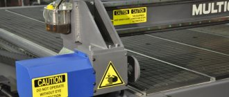
Gantry 3-axis CNC table
Production of homemade versions
When manufacturing, you should initially select the material of manufacture:
- Cast iron is an expensive, heavy, brittle material. It is quite rarely used in the production of a drilling machine.
- Steel is a strong, hard, durable metal, which also has a fairly high cost. Steel can be called the most attractive material.
- Aluminum is a light, fusible, but expensive and soft material. It is quite easy to use in the manufacture of any machine parts. As a rule, mini equipment is created using this alloy.
The above materials are selected for a full or mini machine.
Manufacturing of guides
The accuracy of processing depends on the correct choice of guides. You can make the following designs with your own hands:
They are created with a carriage and bearing units. You can select guides depending on the type of drive. To achieve the highest processing accuracy, plain bearings are used. When using a rolling bearing, friction is significantly reduced and the service life of the device is increased, but significant play appears, which reduces the accuracy of processing.
Rail design
There are two types of guide carriage:
- with increased flange dimensions, which allows mounting from below the table;
- the design without a flange is attached from above using the threaded method.
Let us note that the homemade version of the guide should be closed using stainless steel. Stainless steel can withstand high humidity for a long time.
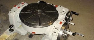
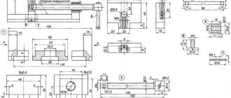
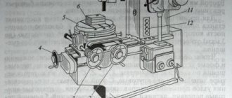
Rotary table design
The figure above shows the simplest version of the rotary table design. A bushing (10) is pressed into the table body (11). The spindle (2) rotates in it. The table faceplate (1) is installed on the spindle. The bushing (7) is also pressed into the body. A rack-type clamp (5) is directed into it, which enters the bushing (3) under the action of a spring (6).
A handle (4) is provided to control the latch. The faceplate is rotated using a rolling bearing consisting of a cage (12), rings (14) and balls (13). To adjust the axial clearance, a nut (8) and a locking screw (9) are used.
Drive types
When creating a small machine, a coordinate table with mechanical feed is often installed. However, there are quite a few types of drives, the selection of which is based on the following criteria:
- processing speed;
- positioning accuracy;
- equipment performance.
In most cases, an electric drive is chosen, during the creation of which a motor is installed.
The essence of this mechanism is to convert rotation into reciprocating motion. The following types of gears are distinguished for the design in question:
When creating a drive, a belt drive is often chosen. A homemade belt-type mechanism is cheaper than others, but the belt quickly wears out and stretches. Also, belt slippage determines the low accuracy of the moving element. All elements of the coordinate steel are connected to each other by welding. In this case, the threaded method of connecting certain parts is also used.
In conclusion, it should be noted that a home-made design is suitable exclusively for equipment for domestic use, since it is practically impossible to achieve the accuracy that industrial models have.
Motion transmission mechanism
The most important part of the future device, no matter whether it is a rotary table for a drilling machine or a cross version, is the mechanism for transmitting movement from the control handles to the device.
It is best to make a drive with a mechanical type of movement; they are manually controlled. In this way, specialists can achieve greater accuracy of movements and high quality of work performed.
The components of the motion transmission mechanism are:
- racks and gears, gears,
- belt mechanisms,
- ball screw drives.
Experts advise choosing the latter type of mechanism, especially when it comes to a cross table; it has many significant advantages:
- extremely small system play,
- the product moves very smoothly, without jerking,
- The ball screw operates quietly,
- under significant workloads it shows high stability.
Experts say that the disadvantage of the mechanism is the inability to achieve high operating speed, but if you are considering a cross table for a drilling machine, then high speed is usually not required.
To save money, the master needs to try to implement belt drives. They are simple and accessible, but have disadvantages:
- low accuracy,
- rapid wear,
- risk of belt breakage under load.
As a conclusion, we note that if a person decides to make a table for a drilling machine with his own hands, then there is nothing fundamentally unrealistic about this. A basic set of materials and tools will help you quickly complete the task. The task for a specialist is to choose the right type of structure and produce high-quality all the critical components of the future device.
Design Features
A coordinate table is a special additional device for a milling or drilling machine, which allows you to move a fixed part along the desired path. Thanks to the convenient design, the labor intensity of the process is reduced and time is saved. The mini-table can be industrial or hand-made. If you know how to work with a welding machine, you can make the device yourself in a private workshop. The advantages of such devices include:
- simplicity of design and ease of use during operation;
- compactness, due to which the machine is not cluttered with equipment;
- saving money in handicraft production.
But a homemade coordinate table allows you to make only small, simple parts. For more professional work, you will need a factory model. Another disadvantage is the relatively rapid wear of the device. In addition, manual manufacturing requires a detailed drawing; the accuracy of assembly and subsequent operational efficiency depend on it.
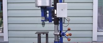
Homemade coordinate table, perhaps? — Homemade machines
Absolutely right, transverse and small longitudinal from a lathe, cast iron bed from a Komunaras drill with a screw feed, the working field turned out to be 300x300, mainly for processing small steel parts and is being invented, now everything is still in the process of experimentation and debugging, but there is positive experience with steel, It seems to cope with cutters up to 6 mm normally, but with a larger diameter problems begin (all mainly from using a 1200 W impact drill as a head), you need to come up with a tough, powerful head, when installing an angle grinder instead of a drill, you get a small grinder
Here’s a photo I took (though the quality is not very good) while working with steel, one has an x35 plate on it, the second photo shows the actual part for working with which the device was intended to work with (in the photo, one part is before processing, the second one, clamped in the chock, has already been passed through three times)
Modified on January 25, 2014 by BM_906
Model selection
Coordinate tables can have different types and structures. The classifications are based on the method of fastening the workpiece, the number of degrees of freedom and dimensions. Based on the last feature, devices are divided into large and small. Equipment can be installed on large tables. Small - mounted directly on the machine. The type of fastening can be of three types:
- Vacuum. It is considered the most effective, but rarer type of part fastening. This is due to the complexity of the design. The principle of operation is to supply air between the tabletop and the part. Changing the pressure allows you to process the workpiece more efficiently.
- Mechanical. A simple fastening method that is easy to implement and use. However, with mechanical fixation, errors are allowed and defects are possible when processing the element.
- Under the own weight of the part. This method is suitable only for working with heavy, dimensional products. Due to their large mass, they remain in place even with significant impact on them.
The number of degrees of freedom affects the functionality of the device. According to this criterion, coordinate tables are divided into three types. The first allows you to move the part in only one direction. This simplified model is suitable for processing flat elements. The device of the second type has two degrees of freedom, that is, the part can be moved in two directions within the same plane. The third type of device has the ability to additionally move the part in the vertical direction.
For self-production and operation in a home workshop, a device with two degrees of freedom and mechanical fastening is suitable.
Mechanical
Vacuum
Under the weight of the part
Purpose and types
In essence, a coordinate table is a movable metal platform on the surface of which a workpiece processed on a machine is mounted. Various methods of such fixation are possible:
Mechanical two-axis table fixed in standard grooves of the working surface of a drilling machine
Depending on their functionality, coordinate tables for drilling machines can have two or three degrees of freedom. Thus, some models can only move in the horizontal plane (X and Y axes), while more technologically advanced ones can also make vertical movements (Z axis). Tables of the first type are used when processing flat parts, and devices with the ability to move vertically are equipped with drilling machines that process parts with complex configurations.
Materials and tools used
To work you will need a welding machine, a drilling machine, an angle grinder with discs, a hammer, brushes, and a corner. At the preparatory stage, it is necessary to select the material for the base of the device, the control mechanism and guides. The accuracy of the future operation of the device, service life, reliability of the device, and financial costs of manufacturing depend on the correct choice of these components. To create a base, one of three metals is suitable:
The first material is rarely used in work. The reason lies in its fragility, heavy weight, and fragility. Steel wins by these criteria, which is why it is often used in production. Its only drawback is its high cost. Aluminum is much more affordable. Its advantages are lightness and softness. But it is only suitable for small-sized tables, since the malleable metal cannot withstand large heavy parts.
Take the survey
When making a coordinate table with your own hands, you need to think about what type of drive the device will have. According to the control method, manipulators are divided into three types: mechanical, electrical, and program control. The latter drive is not used in self-production. The electrical analogue gives a small error, but in private conditions it is problematic to use. For personal home appliances, a more suitable type of control is mechanical. However, it has a drawback - the lack of perfect accuracy.
For manual production, rail or cylindrical guides are suitable.
Cast iron
Steel
Aluminum
Mechanical drive
Electric
Software controlled
Motion transmission mechanism
The most important part of the future device, no matter whether it is a rotary table for a drilling machine or a cross version, is the mechanism for transmitting movement from the control handles to the device.
It is best to make a drive with a mechanical type of movement; they are manually controlled. In this way, specialists can achieve greater accuracy of movements and high quality of work performed.
The components of the motion transmission mechanism are:
- racks and gears, gears,
- belt mechanisms,
- ball screw drives.
Experts advise choosing the latter type of mechanism, especially when it comes to a cross table; it has many significant advantages:
- extremely small system play,
- the product moves very smoothly, without jerking,
- The ball screw operates quietly,
- under significant workloads it shows high stability.
Experts say that the disadvantage of the mechanism is the inability to achieve high operating speed, but if you are considering a cross table for a drilling machine, then high speed is usually not required.
To save money, the master needs to try to implement belt drives. They are simple and accessible, but have disadvantages:
- low accuracy,
- rapid wear,
- risk of belt breakage under load.
As a conclusion, we note that if a person decides to make a table for a drilling machine with his own hands, then there is nothing fundamentally unrealistic about this. A basic set of materials and tools will help you quickly complete the task. The task for a specialist is to choose the right type of structure and produce high-quality all the critical components of the future device.
Manufacturing instructions
Once the type of material and type of construction have been selected, they proceed directly to work. At the first stage, it is necessary to draw up an accurate drawing indicating the dimensions of all parts. If there is no ready-made scheme, you should develop it yourself. The final result is largely determined by the accuracy of the location of the parts relative to each other. The process of assembling a coordinate table with a mechanical drive consists of the following steps:
- the main assembly is welded from a metal profile 2 mm thick;
- check the geometry of the cross and clean the seams with a grinder;
- a block of guides is assembled on the welded central unit (travel is 94 mm);
- nuts of size M10 are installed inside the profile;
- a handle with a bearing is assembled on a threaded rod (M10);
- weld the base from a corner having a U-shaped configuration;
- screw all parts onto the built-in nuts;
- lubricate moving elements with technical oil;
- install the device on the bed of the milling machine.
The manipulator structure should be assembled on an absolutely flat surface.
Review and comparison of factory models
| Model | KT70 | KT150 | G-5757 | KRS-475 |
| Table dimensions, mm | 200*70 | 200*200 | 312*140 | 475*155 |
| Longitudinal movement, mm | 134 | 150 | 203 | 330 |
| Transverse movement, mm | 46 | 150 | 125 | 150 |
| Vernier division, mm | 0,05 | 0,05 | 0,02 | 0,02 |
| Weight, kg | 1,14 | 4,9 | 17 | 23,5 |
| Price, rub | 8046 | 16510 | 11900 | 14000 |
- Types and varieties of metal cutters for the machine
- Classification of turning cutters for metal: carbide, with replaceable inserts, alloyed
- Technology for sharpening drills of various types
- Metal machines
- Woodworking machines
- Universal machines
- Special machines
- Machine equipment
- Machine Reviews
- Contacts and advertising
Machine Reviews
- Review of the FSSH-1A milling machine: design and technical parameters
View all test reviews
- Milling machine knowledge test
- Lathe knowledge test
- Test for knowledge of industrial machines and accessories for them
Machine passports
Useful tips
The instructions, which describe how to make a coordinate table with your own hands, explain the process step by step. However, minor problems may arise during operation. To avoid them, it is recommended to adhere to safety precautions and take into account the advice of experts. The most important of them:
- if you plan to process plastic or wood, then the base of the manipulator can be made of aluminum;
- with device dimensions of 35 x 35 cm, it is advisable to adjust the total length of the guides to 30 cm;
- to protect the device from chips before installation, it is recommended to place a piece of plywood under it;
- when using cylindrical guides, there is no possibility of connecting a lubrication supply system, so all parts must be lubricated manually;
- When assembling, it should be taken into account that the plain bearing provides better machining accuracy, while its counterpart (friction bearing) leads to some play.
To carry out welding work, safety precautions must be observed. It involves the use of special clothing, a protective mask (shield), suede or tarpaulin gloves. The room in which the assembly is carried out must be ventilated or have a high-quality exhaust hood. When working outdoors, a canopy is required. Near the workplace, means and materials must be prepared to extinguish a possible fire.
The manufacture of a simple type coordinate manipulator can be mastered by a master with welding skills . It is not difficult to obtain a reliable and convenient product if you strictly follow the conditions of the drawing and the assembly algorithm. The home device allows you to engage in small-scale production of metal, wood, and plastic parts. The service life of such a device depends entirely on the quality of installation and the volume of drilling and milling work performed.
Do-it-yourself lifting table for a drilling machine
A coordinate table for a drilling machine helps to make the operation of the unit precise, smoothly move the workpiece to the desired position, and avoid jumps and twisting of the part. The efficiency of working on any type of machine increases significantly when using a coordinate table, especially one made by yourself.
A coordinate table makes drilling faster, easier and more accurate. If a person has a set of tools and materials on hand, such equipment is easy to do independently.
Tables for drilling machines come in several different types, can be made of different materials and function on different principles. This is a simple fixing device, with the help of which the workpiece is secured in the required position.
X-ray table model
With the help of a table, a part is able to change its position and angle during processing; manipulation allows you to perform different types of processing without removing or moving the part. The methods for fixing equipment are as follows:
- using vacuum and differential pressure;
- mechanical devices;
- the part is held on the table independently due to its heavy weight.
For amateurs who are planning to make a table for a drilling machine with their own hands, the second fixation option is most suitable.
The workpiece being fixed in different installations has a different number of degrees of freedom - two or three.
In the first case, she is able to move only along the X and Y coordinates; in the second, the ability to move up, down or along the Z coordinate is added.
For home use, two degrees of freedom is quite enough.