News:
ATTENTION TO THOSE WHO WANT TO REGISTER ON THE FORUM. Problem activating your account? Write to (ignel(gav)mail.ru, ICQ 50389649), indicating your nickname and the address from which you registered. Don't forget to look at the forum rules. Ignorance of the rules does not exempt you from responsibility! Don't forget to look at the TB Section. Knowing the rules can save lives. Have questions about using the forum? Look for answers in the FAQ (FAQ). There's a lot of useful stuff there. Looking for interesting materials? Guide to master classes from our forum members
Author Topic: installing knives on a jointer (video) (Read 15225 times)
0 Users and 1 Guest are viewing this topic.
A jointing machine is available in almost all educational workshops of schools, most training and production plants and various industries. Setting it up and especially accurately installing the cutters on the shaft is a rather labor-intensive operation. Their correct installation should ensure:
- strictly cylindrical surface of rotation of the cutting edges;
- parallelism of the plane of the rear table of the machine and the generating surface of rotation of the knives;
- displacement of the front table relative to the rear table by the thickness of the chips being removed.
To adjust the jointer, it is recommended to use a block of solid, well-dried wood, carefully jointed on all four sides. However, the accuracy of setting knives with its help, even for an experienced installer, does not exceed 0.08-0.15 mm (the difference in the sizes of the cutting circle radii).
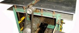
In order to increase the accuracy of knife installation and reduce the time for setting up the machine, we suggest using the device shown in the figure.
Figure 1. A beam with an indicator for setting up a jointer
A dial indicator with a division value on a dial scale of 0.01 mm must be installed in a block 2 jointed along the bottom surface, 200 mm long and with a cross-section of 30X40 mm. To do this, at a distance of 50 mm from the end (on the side 30 mm wide), a hole is drilled along the diameter of the indicator sleeve (8 mm). In the middle of the same side from the end to the hole, a cut is divided with a hacksaw, and at a distance of 20 mm from the end, in the middle of a 40 mm wide edge, a hole 0 6 mm is drilled for a coupling bolt with nut 5, which serves to secure indicator 3 in the block.
When setting up the machine, the device is installed on table 1, 7 and the readings of the indicator arrows are recorded on a sheet of paper. Knife 10 is inserted into one of two grooves on the shaft body 9 so that the cutting edge protrudes 2-3 mm above the chip breaker 6, and is slightly secured with the middle bolt 8. Then the block 2 with indicator 4 is moved along the back table 1 until the tip 4 of the indicator will not fall on the cutting edge of the knife 10. The arrow readings at this moment should correspond to what was recorded earlier. If there are discrepancies, then you should slightly raise or lower the knife (or the back table). The adjustment continues until the indicator readings are the same both at the middle point of the knife and along its edges. After this, the knife is secured. Based on the same (recorded at the beginning) indicator arrow readings, the second knife is installed.
To adjust the front table, add the thickness of the chips being removed to the previously recorded indicator readings and set the table based on the resulting amount.
The use of the device in training workshops is not limited to installing planing knives when setting up a jointing machine. With its help, you can check the parallelism of the surfaces of the rear and front tables of the planing machine, install milling knives in cutter heads, check the correct set of saw teeth, etc.
Read also: Wood saw blades for circular saws
A jointer is used to process wood mechanically using a cutting tool. It produces planing in a straight direction of wooden parts along the surface or edges. Based on the number of cutting mechanisms, a distinction is made between double-sided and single-sided machines; the first version of the equipment is designed for jointing two adjacent surfaces simultaneously.
The supply of the workpiece to work is organized mechanically or manually. For mechanical movement of parts, an automatic feeding device attached to the machine or a conveyor built into the unit is used. to remove dust and chips.
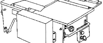
The device of a jointing machine
The unit consists of structural parts:
- beds;
- table;
- fan fencing;
- guide ruler;
- knife shaft.
The bed is designed to support all elements of the machine and the workpieces being processed and can withstand significant weight. It is made from a profile with a large margin of safety, for example, a channel or an I-beam.
The table is equipped with two plates - front and back. The back plate with its surface is located tangent to the cylindrical contour obtained by torsion of the knife blades. The surface of the front plate is located below the rear plate by the thickness of the layer being removed in one pass of the part. The guide ruler and work table are made with smooth and even surfaces.
The knife shaft is installed between the work table plates. Cutting knives are selected of the same shape and weight, and the edges of the knives are set so that they simultaneously and evenly describe the cylindrical processing contour.
The guide ruler is located in grooves on the working surfaces and secured with bolts. The ruler moves across the table when the width of the workpiece changes.
The fan shaft guard is secured to the front plate of the work table. To protect the knife shaft, there is a fan circuit pressing spring against the guide bar.
It is most convenient to work with workpieces from one to one and a half meters; short parts are dangerous and inconvenient to hold; long parts are torn out due to the fact that their dimensions exceed the length of the table. The slot of the knife shaft is equipped with two steel plates that are mounted flush with the surface. The distance from the edge of the lining to the contour described by the blades should not be less than 3 mm , while the edges are polished and nicks and depressions are removed from them.
Knife shafts are cylindrical in shape, but it is not recommended to use segment linings for this, which in the process become calved due to high centrifugal force or relaxation of the fastening. A common method is to clamp knives into trapezoidal grooves and fix them with bolts and wedges; in this option, when rotating, the knives are additionally jammed.
There are several ways to adjust the parallelism of the feed and take-up tables.
A simple setting method is used for household machines.
Such devices, as a rule, do not have separate (4) table mounting supports.
- The feed table is set to the height of the receiving table
- The straight edge is placed on 2 tables
- The absence of gaps under the ruler is controlled.
In case of gaps, one plane is drawn under the table guides using measuring pads.
The correct way to set up professional jointing equipment:
- Checking the position of the planing shaft relative to the receiving table. The knife shaft should be parallel to the receiving table and be below its level by the height of the knife exiting the planing shaft by 2-3 mm. Depending on the design of the machine, this operation is carried out either by installing measuring plates under the supports of the knife shaft, or under the supports of the receiving table.
On some machines, the receiving table also has the ability to adjust its position by turning the eccentrics. In this case, the table is installed using the adjusting nut 9.
- A straight edge is placed on the receiving table so that its entire length is on the receiving table, and its free end hangs above the feeding table. If necessary, to prevent it from overhanging the feeding table, the end of the ruler can be secured to the receiving table with a clamp.
- A measuring probe measures the distance from the straight edge to the table at 4 points (1,2,3,4). These points are located above the table supports. In this case, measurements are carried out in 2 stages: when the ruler is located above points 2 and 4, then the ruler is moved parallel to the other edge of the table and measurements are taken at points 1 and 3.
- The point with the shortest distance is selected. Let this be point 2.
- Raise the feed table until point 2 touches the straight edge.
- Using a measuring probe, we determine the distances at four points and write them down on the table. Example t.1-0.3mm, t.2-0mm, t.3-0.2mm, t.4-0.1mm
- These values correspond to the thickness of the measuring pads, which must be placed under the supports at the appropriate points.
- After installing the measuring plates, we once again check the parallelism of the supply and receiving tables.
The last operation must be checked with the table position at the top and bottom. Sometimes there are “complicated cases” of unqualified repairs, when the adjustment is carried out according to the method described above, and the last point (8) is not performed. The tables lose parallelism when the gouging height (removal thickness) changes. This situation may arise if, during the long life of the machine, the eccentric supports of the table lift were repaired (for example, the rod connecting the eccentrics of the lifting supports was changed. Moreover, the new rod turned out to be “slightly” different in length. Or when installing the old rod, one eccentric installed in the upper position, and the other in the lower position.
Accordingly, when the position of the lever changes, the front part of the table rises and the rear part lowers.
Preparing the jointer for operation
Before planing begins, the structural parts are adjusted and the installation of working elements is monitored.
Adjusting the jointer table
The difference between the surfaces of the rear and front plates is set in the range from 1.25 to 1.5 mm, this makes it possible to align the plane in two passes of the workpiece. To ensure that the installation parameters of the rear plate do not change during operation, locking devices are provided for fixation. Provide a distance of 5 mm between the knife shaft and the sponge
The material for the table slabs is gray cast iron. On the reverse side of the working plane there are rigid ribs to reduce vibration movement. To prevent wear of the slab ends under abrasive loads, steel linings are made; they also serve to reduce the distance from the edges of the blades and provide additional safety.
Installing the working blades
Knives are selected with straight blades, the deviation is checked with feeler gauges and a ruler, and the gap should not exceed 0.1 mm. Prepared and tested knives are installed in sequential order, with the edges of the blades protruding above the edge of the steel plates of the slot by 1-2 mm. The parallelism of the knives is checked with a control bar or a special indicator.
Read also: Metal products for the garden
When using an indicator, the installation accuracy is greater than when using a control bar. Avoid distortions of the blades when fastening; they should be located on a common cylindrical rotation contour, with the axis of the cylinder coinciding with the axis of the knife shaft. It is prohibited to use any type of spacers when installing blades; knives that have become unusable due to grinding or changing the width of the blade must be replaced.
Control block
Used to adjust the jointer when installing the cutting blades. The device is made from hard dried wood, the control edges are processed with high precision. The bars are made with the following cross-section:
- 20×30 for length 400 mm;
- 20x50 for length 400 or 500 mm;
- 30x50 or 30x70 for length 500 mm.
During the use of the bar, its edges are checked and additionally aligned and planed to remove teeth and depressions. When installing knives, the measuring device is placed on the back plate of the work table. By turning the shaft by hand, ensure that the blades touch the underside of the block. The position is controlled at three points of the shaft, in the middle and at the ends at a distance of 70-100 mm from the edge. The adjustment is carried out until the knives are evenly protruded at all intervals and touch the same.
Setting up the jointer
When processing wooden parts, you cannot do without an electric jointer. Before starting work, you need to set up the machine; this applies to tools of any size and power. Both operational safety and the accuracy of parts manufacturing depend on correct settings.
And precision, in turn, reduces the time spent and improves the quality of products. Each jointer has two tables, one rigidly fixed behind the knives and a height-adjustable table in front of the knives.
Two or three removable knives are attached to the working drum, which also need to be positioned correctly. But it’s better to start by adjusting the table.
1. We set the tables on the same level and use a good building level to check the surfaces of the tables. They must be exactly at the same level; there should be no gaps or sagging under the ruler. If the edges of the tables sag, the part will turn out concave when planing. If there is a gap in the middle under the level, then the edges of the parts will turn out to be curved outward. Both are bad, the workpieces are bent and the plots are extremely difficult to trim accurately when gluing.
For a more accurate check, in addition to a ruler, you need to use two straight squares. The squares are placed on both tables and connected to each other. At the junction you will see gaps that need to be straightened.
All jointers have adjustment bolts. They may differ in appearance and shape, but the principle of operation is the same. By screwing or unscrewing, we adjust the level of the surface of the fixed table. Then we fix the bolts with locknuts or additional clamps.
2. In addition to the general level of the tables, you must immediately pay attention to the angle between the tables and the guide ruler. Check this angle at all points along the entire length of the guide. On old jointers, sagging of the metal tabletop itself, or even bending of the guide ruler, may appear.
But with careful fitting and adjustment, an acceptable level can be achieved. In any case, it is imperative to properly adjust the angle between the table and the guide; it must be exactly 90*. As a rule, the clamp for setting the angle is made with a handle, so you need to loosen the clamp, align the ruler with the square and tighten the clamp again.
3. When installed, the knives are aligned on the fixed tabletop. All knives must be set at the same level, otherwise only one, the most protruding one, will work. But one knife does not produce such a high-quality surface; it will tear the wood. In addition, the load on the cutting parts increases sharply and, as a result, additional vibrations occur. Close to the topic of the master's measuring tools.
It is better to check the installation of knives using a planed block of hard wood. We place the block on a stationary table and move it in the direction of the knives. The block should slightly catch and rotate the knives, but there should be no gap between the block and the jointer's work table. In general, tuning accuracy is not measured in millimeters or even tenths of a millimeter. We are talking about an accuracy of 0.02 - 0.03 mm. .
4. Of course, knives, like the working surfaces of tables, must be adjusted across the entire width of the jointer. There are different devices for this, but craftsmen more often check the level using one block applied at different points on the table.
The work will be easier if you assemble a block of two bars and immediately check the level of installation of the knives at both ends of the drum. Another method for fine tuning is to use a piece of glass no wider than the length of the knives. It is better to prepare such glass in advance and be sure to sand the edges to avoid cutting yourself.
Source
Planer-thicknesser unit
It is a combined machine with a combination of thicknessing and jointing processing. After the initial sawing of the boards, they are sent to the final removal of all irregularities. It differs from a planing unit in that it allows planing to a selected depth. The knife shaft with blades is located between the receiving table, fastened to the frame, and the receiving surface; in some models, the cutting tool is installed under the table or on top of the plane. To set it to size and adjust it, use a ruler attached to the body.
Simultaneous jointing and surface planing allows the workpiece to be planed to a selected depth, which is why it is used in large production facilities. It works great on a construction site, where wood is delivered with primary processing, and subsequent planing to size is carried out on the site before installation in the structure.
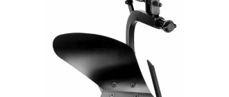
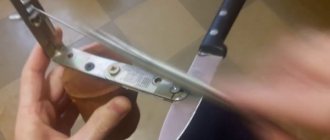
Installation of knives
Performed after they have been sharpened or need to be adjusted.
The correct installation of the knives can be easily checked after inspecting the trimmed workpiece. In the case of “knife failure” - the knife is installed below the level of the receiving table, a “breakout” of the wood will be noticeable at the beginning of the workpiece. With a high knife position, the same effect is visible at the end of the processed workpiece.
The correct installation of the knives is clearly visible in the figure: when turning the planing shaft, the knives should touch the workpiece but not tear it off the table.
Source
Making a machine yourself
To begin with, determine the number of functions of the future unit . It could be:
- just a planer with one planing operation;
- a combination of a jointer and a circular saw, which doubles the usefulness of the equipment;
- they add grinding, sharpening and drilling functions, but for your own workshop, making a complex set of equipment with your own hands is a difficult task.
Often, craftsmen independently make a jointing machine with a sawing function, while the torque is transmitted from one electric motor, which includes structural elements:
- The bed can support the weight of the work plane and installed electrical and mechanical equipment. In a workshop, a channel with a shelf thickness of at least 10 mm is used to make the frame. The structure can be made stationary (welded) or provided with bolted components for disassembly if necessary. The first option is more reliable and is used if a portable machine is not needed. Sometimes the desktop itself acts as a bed.
- Working tools include knives and saws; the work of processing and sawing workpieces depends on their quality. Reliable and strong steel is used for cutting blades; the saw teeth must be equipped with Pobedit tips.
- Without a rotor, to which all the tools are attached, not a single woodworking machine will function, so attention is paid to its selection. Most often it is made by a specialist turner according to the drawings offered to him.
- The design of a jointing unit with a sawing function provides three working surfaces - one serves as a table for the circular saw, the other two feed and receive the workpiece during the jointing process. Multilayer plywood, the thickness of which is at least 5 mm, or sheet metal, is used as a covering. Typically, the feed surface is made 2-3 mm below the receiving side to facilitate the process and reduce vibration load.
Read also: Is it possible to connect a home theater to a TV?
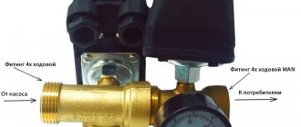
Electric drive of the machine
The operation of the jointer and saw is based on rotational functions, which is why the drive is called the heart of the unit. A three-phase motor is suitable as an electric motor; sometimes the wiring is re-equipped for this in the workshop. Three-phase units with a voltage of 380 V are characterized by high power and suitable torque. The minimum permissible engine power is 3 kW, the maximum is not limited.
The transmission of rotation from the engine to the shaft is carried out by means of a belt drive. V-shaped double-ribbed belts work well in such conditions; they are reliable in operation. The electric motor is mounted using a console inside the frame structure of the bed; the installation method helps to regulate the tension of the belts. Another way is to mount it using a slide - this still allows for adjustment, but the engine itself is more firmly fixed.
To accelerate the rotation of the shaft, two pulleys of different diameters are used. The larger one is placed on the electric motor, the smaller pulley is placed on the shaft. To supply electrical power, choose a cable with four cores; such wiring reduces the danger of operation.
Main stages of work
The progress of work in the manufacture of a jointing machine looks like this:
- The first step is to draw up working drawings, without which there is no point in starting work. Sometimes you need to reconsider some node, change the size of a structural element, all this is first done on the plan, then on the machine.
- The dimensions from the drawing are transferred to the workpieces and all structural parts of the equipment are made. It is important to provide a place for the location of rotor bearings, which is made of several elements, using clamps and glue for connection. The recesses are made exactly according to the dimensions of the bearing, and the engine is installed.
- The rotor and bearing are assembled and installed. They make a belt drive and use it to connect the shaft to the engine, ensuring smooth and free rotation of the rotor in the bearing.
- A working surface consisting of receiving and supply parts is installed and finished with metal or plywood. For correct positioning in the horizontal plane, use a building level.
- They provide a starting switch and a switch for the electric motor; after a test run, the machine is ready for operation. To ensure its long-lasting performance, you should follow the recommendations for working with it.
Features of operation
Woodworking equipment, like any other, requires attentiveness and caution, compliance with certain operating rules:
- Regular inspections and preventive repairs are carried out, blades are sharpened, saw blades are changed;
- Preventative injection of bearings, control check of engine operation, inspection of belts, tightening of sagging, cleaning of contacts and other work are carried out;
- The engine is provided with a protective casing; operation without it is prohibited;
- The machine operator's workplace must be well lit, the floor covering is made of rough materials that prevent slipping;
- an assistant is invited to work with long and large parts, this will protect the master from injuries and machine breakdowns;
- keep the workplace clean, promptly remove chips from the floor and inside the unit (after turning off the electricity), remove unnecessary objects from the workspace around the machine.
Operating rules are shown in the video.
The use of electrical wood processing is effective compared to manual planing and jointing. To obtain high-quality workpieces without injuries and accidents, follow safety precautions and equipment operating rules.