Place of the device in the water supply system
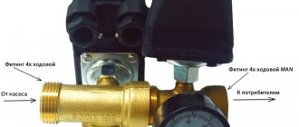
The hydraulic accumulator (HA) consists of a container, a bleed valve, a flange, a 5-pin fitting (tee) with couplings for connection, as well as a pressure switch (control unit), which sets the rhythm of all work.
Functions:
- main control element
- ensures work without overloads
- controls optimal filling of the tank with water
- extends the service life of the membrane and all equipment in general
A pressure gauge that shows the pressure in the tank is included in the kit or can be purchased separately.
The pump pumps water out of the well and directs it through pipes. Next, it enters the GA, and from it into the home pipeline. The purpose of the membrane tank is to maintain stable pressure, as well as the operating cycle of the pump. There is a certain maximum activation for it - about 30 per hour. If exceeded, the mechanism experiences stress and may fail after a short time. The water pressure switch must be adjusted so that the devices operate as expected, without exceeding the critical load.
Setting up a storage tank means creating the required number of atmospheres in it and correctly setting the pump response thresholds
What is a hydraulic accumulator and how does it work?
Externally, the device looks like a tank with a horizontal or vertical layout, which is installed in a suitable place (more on this later). It is connected, on the one hand, to the water supply pump, and, on the other hand, to a pressure switch and internal piping.
A typical battery designed to work with a drinking water supply network consists of the following elements:
- A working tank with a certain volume.
- An elastic inner container, which is made from high-strength butyl rubber and is hermetically located in the internal volume of the tank.
- A pneumatic valve installed on top of an elastic container that controls changes in the pressure of water pumped into it.
- Safety valve that regulates the limit value of air pressure.
- Threaded connecting pipe through which water enters the accumulator.
- Connecting brackets used to mount the device.
Optionally, a pressure gauge, connecting pipes, and a valve for manual pressure release can also be supplied to the accumulator.
It should be noted that the same hydraulic accumulator cannot be used both to regulate water pressure in the cold water supply network and for use for heating or preheating water. The pressures and temperatures will be noticeably different, which can negatively affect the reliability of the operation of the system elements and the durability of the accumulator itself (more precisely, the elastic membrane).
The operating principle of a hydraulic accumulator for a water supply system is as follows. A pump (submersible or surface) supplies water under a certain pressure, which enters an elastic container. It expands, thereby increasing the pressure of the air, which is in the enclosed space between the membrane and the inner walls of the tank body. The air pressure increases, which serves as the basis for turning off the relay that controls the pump. Water under established pressure enters the house network to its distribution points. As it is consumed, and also due to resistance in the pipelines, the water pressure begins to decrease. Accordingly, its volume in the membrane decreases, which leads to a decrease in air pressure. When a certain minimum level is reached, the pressure switch is activated, which turns on the pump again, and the cycle repeats.
The design of the device allows for its partial disassembly, which is necessary for preventive cleaning of internal surfaces from salt deposits.
Design and principle of operation
The device looks like a box of various shapes with controls under the lid. It is attached to one of the outlets of the fitting (tee) of the container. The mechanism is equipped with small springs that are adjusted by turning the nuts.
Operating principle in order:
- The springs are connected to a membrane that responds to pressure surges. An increase in indicators compresses the spiral, a decrease leads to stretching.
- The contact group reacts to these actions by closing or opening the contacts, thereby transmitting a signal to the pump. The connection diagram necessarily takes into account the connections of its electrical cable to the device.
- The storage space fills up and the pressure increases. The spring transmits the pressure force, the device operates according to the set values and turns off the pump, sending it a command to do so.
- The liquid is consumed - the pressure weakens. This is fixed, the engine turns on.
The assembly consists of the following parts: a housing (plastic or metal), a membrane with a cover, a brass piston, threaded pins, metal plates, cable sleeves, terminal blocks, a hinged platform, sensitive springs, and a contact assembly.
The operating algorithm of the control device is as simple as possible. The mechanism responds to changes in the number of atmospheres inside the drive. The moving platform is raised or lowered by springs depending on the pressure on the piston, which in turn interacts with contacts that signal the pump to start or stop pumping.
Installation
Often the HA kit is sold disassembled, and the control unit must be installed yourself.
Connecting the pressure switch to the hydraulic accumulator looks like this in stages:
- The station is disconnected from the network. If water has already been pumped into the storage tank, it is drained.
- The device is fixed permanently. It is screwed onto the 5-pin fitting of the unit or onto the outlet pipe and must be firmly fixed.
- The wiring diagram is normal: there are contacts for the network, pump, and grounding. The cables are passed through holes on the housing and connected to contact blocks with terminals.
Electrical connection to the pump
How to choose tank volume
You can choose the tank volume arbitrarily. There are no requirements or restrictions. The larger the volume of the tank, the greater the supply of water you will have in case of a shutdown and the less often the pump will turn on.
When choosing a volume, it is worth remembering that the volume that appears in the passport is the size of the entire container. There will be almost half as much water in it. The second thing to keep in mind is the overall dimensions of the container. A 100 liter tank is a decent-sized barrel - about 850 mm high and 450 mm in diameter. You will need to find a place somewhere for it and the harness. Somewhere - this is in the room where the pipe from the pump comes. This is where all the equipment is usually installed.
If you need at least some guidelines to select the volume of a hydraulic accumulator, calculate the average flow rate from each water intake point (there are special tables or you can look at the data sheet for household appliances). Sum up all this data. Get the possible consumption if all consumers work simultaneously. Then figure out how many and which devices can work at the same time, calculate how much water will be consumed in a minute in this case. Most likely by this time you will have already come to some decision.
To make it a little easier, let’s say that the hydraulic tank volume of 25 liters is enough to meet the needs of two people. It will ensure the normal functioning of a very small system: a faucet, a sink and a small one. If you have other household appliances, the capacity must be increased. The good news is that if you decide that the current tank is not enough for you, you can always install an additional one.
Settings
Before adjusting the relay, you need to take into account that its values are inextricably linked with the pressure inside the membrane tank. First you need to create the required amount of pressure inside it, and then move on to working with the control in question.
The adjustment is carried out in 3 stages:
- pressure inside HA
- pump start level
- shutdown mark
For optimal operation, it is necessary to adjust the parameters several times experimentally, taking into account the water flow, the height of the pipes and the pressure in them.
Indicators inside the accumulator
It is advisable that the pressure adjustment in the accumulator take into account the following examples and rules:
- for a one-story house, 1 bar is enough, and if the tank is installed in the basement, then add 1 more
- the value must be greater than at the highest point of water intake
- how many atmospheres should be inside the container is determined by the following formula: add 6 to the height of the pipes to the highest point of water intake and divide the result by 10
- if there are many consumption points or the branching of the pipeline is significant, then a little more is added to the resulting figure. How much to add is determined empirically. There is the following rule for this. If the value is too low, then water will not be delivered to the devices. If it is too high, the HA will be constantly empty, the pressure will be too strong, and there will also be a risk of membrane rupture.
In order to increase the pressure in the accumulator, air is pumped up with an ordinary bicycle pump (there is a special spool on the body); to lower it, it is vented. The pneumatic valve for this purpose is located under the decorative trim. The procedure must be done in the absence of water pressure, which requires simply closing the taps.
The value of the indicators is determined by a pressure gauge connected to the spool. The correction is made after the pump has turned off. The pressure difference is created by opening the tap at the nearest point.
Manufacturers standardly set the pressure in the tank to 1.5 - 2.5 bar. Its increase reduces the usable space inside the container and increases the pressure in the system - this must be taken into account when calculating.
Basics of adjusting thresholds
There are two springs with nuts: the larger one is responsible for the values for turning off the pump, the smaller one is for turning it on. The bolts are loosened or tightened, thereby making adjustments.
Setting up the accumulator pressure switch will be of high quality if you follow these rules:
- the average recommended difference between the values for turning the pump on and off is 1 - 1.5 atm
- the pressure inside the HA must be lower than the set value to turn on the pump by 10%. Example: if the activation mark is set to 2.5 bar, and the switch off mark is set to 3.5 bar, then there should be 2.3 bar inside the container
- the hydraulic accumulator and control unit have their own load limits - when purchasing, you need to check whether they coincide with the calculations for the system (pipe height, number of intake points, flow rate)
The mechanism in question controls the maximum and minimum pressure in the tank. It maintains the difference in its values when the station is activated and switched off. The limit of its settings depends on the power and hourly flow rate of the pump.
Factory parameters are indicated in the product data sheet. Usually they are like this:
- limit limits – 1 – 5 atm
- pump operating range – 2.5 atm
- starting point – 1.5 atm
- maximum switch-off level – 5 atm
Preparation and example of setting the required values
Preparation:
- tank is connected
- the control unit is adjusted under pressure, the system is not disconnected from the power supply
- inside the unit the pressure should be 10 - 13% lower than that of the pumping station. That is, approximately 0.6 - 0.9 atm than the mark at which the engine turns on
- all taps are closed
- the set level is checked with a pressure gauge within an hour to make sure there are no leaks
- remove the block housing cover to have access to the nuts and observe the springs
Setting with an example of setting marks of 3.2 atm to turn off and 1.9 atm to turn on (two-story house):
- Start the pump to determine the pressure in the system. It should fill the storage part of the device and increase the pressure.
- They determine at what pressure gauge reading the shutdown will occur (usually no more than 2 atm.) When exceeded, a small spring comes into action, which is clearly visible.
- The motor is stopped above 3.2 - 3.3 atm, this figure is reduced by rotating the nut on the small spring a quarter turn, since it is very sensitive, until the motor turns on.
- They check with a pressure gauge: 3 - 3.2 atm will be enough.
- Turn on the tap to relieve the pressure and so that the HA is freed from the liquid and record the pump activation mark with a pressure gauge, usually 2.5 atm - the lower pressure indicator has been reached.
- To reduce the lower threshold, rotate the large spring bolt counterclockwise. Next, start the pump until the pressure rises to the required level, after which you need to check the pressure with a pressure gauge. An acceptable value is 1.8 - 1.9 and the nut is rotated clockwise.
- Once again, adjust the small spring a little, clarifying the already set thresholds.
The adjustment bolts are very sensitive - turning just 3/4 of a turn can add 1 atm. The pressure of the switched-on pump should be 0.1 - 0.3 atm higher than in an empty storage tank, which will prevent damage to the “bulb” inside it.
The setup process in brief
For a better understanding of how to set up a pressure switch, we will outline the process more clearly:
- pump activation mark (minimum pressure): rotating the large spring bolt clockwise increases the starting mark, counterclockwise decreases it;
- value for shutdown: move the small spring, when tightening - the pressure difference increases, when unscrewing - the actuation mark decreases;
- the result is checked by opening the tap and draining the water, recording the moment the pump is turned on;
- The internal pressure force is adjusted by deflating or pumping air and checking this with a pressure gauge.
Increasing the factory switching parameters (above 1.5 atm) creates a risk of critical load on the hydraulic tank membrane. The operating range of the pump is adjusted taking into account the maximum possible load for the water fittings. The sealing rings of household taps can withstand a maximum of 6 atm.
Types of hydraulic tanks
Tanks are made in vertical and horizontal configurations. In this case, the operating principle is the same for both types. A small difference in vertical tanks is the presence of a special valve in the upper part of the structure. The use of this device is necessary to bleed air that accumulates in the upper part of the vessel. The frequency of bleeding depends on what pressure there should be in the accumulator (50 liters or more).
Small devices do not have special devices for pumping air. This process is carried out by completely draining the water.
In horizontal tanks with a volume of 50 liters or more, a special tap or drain is installed for bleeding.
In the process of selecting a tank by type of design, you should take into account the location, as well as its dimensions.
Maintenance, problems, operation
Preventative actions and repairs:
- mechanical sensitive parts need to be checked and adjusted
- It is advisable to clean the contacts
- If it doesn’t work, don’t rush to disassemble the mechanism - first try lightly tapping the body with a not too heavy object
- Rocker joints are lubricated with grease once a year
- do not tighten the adjustment nuts completely - the mechanism will not work
If the device does not hold pressure, does not work correctly, or does not work at all, refrain from hasty conclusions and do not throw it away. Dust, debris, sand in the membrane space prevent it from reacting normally. Steps to fix the problem are:
- Unscrew the 4 bolts on the bottom, remove the cover with the inlet pipe and the cover.
- Carefully rinse the membrane and the cavities around it.
- Install all elements in reverse order.
- Set the thresholds again and carry out a test run.
Experts recommend that before setting up the relay correctly, do not exceed the upper threshold by more than 80% of the maximum permissible values for a specific model, which are indicated in the instructions (standard about 5 - 5.5 atm.).
For high-quality operation, there should be no air in the pipeline. Periodically (once every 3-6 months) you need to check the set response thresholds, pressure indicators in the HA, and bleed or pump in air. Before you start setting up, you need to find out whether the pressure switch for the hydraulic accumulator and the unit itself can withstand the required loads, and whether its technical capabilities meet them.