There are a lot of diagrams of various soldering stations on the Internet, but they all have their own characteristics. Some are difficult for beginners, others work with rare soldering irons, others are not finished, etc. We focused specifically on simplicity, low cost and functionality, so that every novice radio amateur could assemble such a soldering station. Please note that we also have an SMD version of this device!
What is a soldering station for?
An ordinary soldering iron, which is connected directly to the network, simply heats constantly with the same power. Because of this, it takes a very long time to warm up and there is no way to regulate the temperature in it. You can dim this power, but achieving a stable temperature and repeatable soldering will be very difficult. A soldering iron prepared for a soldering station has a built-in temperature sensor and this allows you to apply maximum power to it when heating up, and then maintain the temperature according to the sensor. If you simply try to regulate the power in proportion to the temperature difference, then it will either warm up very slowly, or the temperature will fluctuate cyclically. As a result, the control program must necessarily contain a PID control algorithm. In our soldering station, we, of course, used a special soldering iron and paid maximum attention to temperature stability.
Soldering station Simple Solder MK936
Description of the IR soldering process
The challenge when working with BGA components is the need to heat and melt large numbers of solder balls at once.
When they are heated, some heat is transferred to the circuit board due to the thermal conductivity of the materials. The heat provided by the soldering station is no longer enough.
Increasing the heating time or increasing the temperature does not have the best effect on the microcircuit. It may overheat and fail.
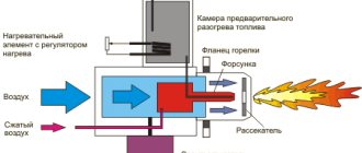
The solution suggests itself - you need to preheat the circuit board from below, without exposing the chip to heat. It can be heated either by air flow or by calm infrared radiation.
As a result, as the temperature of the board material rises, the heat dissipation from the pin legs will decrease and it will take less temperature and less exposure time to melt the solder balls.
When using infrared soldering, special devices are used for bottom heating - heat tables. This is the operating principle of an infrared soldering station.
Infrared soldering has many advantages over hot air soldering. If with hot-air soldering it is possible to control only the speed of air flow from the nozzle and the temperature of the heating element, and it is completely impossible to control the outflow of air, then with infrared soldering the temperature of the solder can be controlled throughout the entire work cycle.
The use of an infrared soldering station allows for more precise impact on a specific area of the board, which is difficult when soldering with hot air.
And during repair work, the task is precisely to replace one or more components of the circuit without affecting others at all.
Specifications
- Powered by 12-24V DC voltage source
- Power consumption, when powered 24V: 50W
- Soldering iron resistance: 12ohm
- Time to reach operating mode: 1-2 minutes depending on supply voltage
- Maximum temperature deviation in stabilization mode, no more than 5 degrees
- Control algorithm: PID
- Temperature display on a seven-segment indicator
- Heater type: nichrome
- Temperature sensor type: thermocouple
- Temperature calibration capability
- Setting the temperature using the ecoder
- LED to display soldering iron status (heating/operating)
Operating principle and general characteristics
Before you try to make such a device at home yourself, you need to familiarize yourself with its main features. Such equipment consists of the following parts:
- Control module. It helps regulate the heating temperature. It consists of a microcontroller responsible for heating the tip.
- Soldering iron. This is the main structural element with which components are soldered.
- Stand. It is located near the control module. Needed to secure a heated instrument when not in use.
Additional Information! Some models are equipped with elements to relieve static voltage.
Schematic diagram
The scheme is extremely simple. At the heart of everything is the Atmega8 microcontroller. The signal from the optocoupler is fed to an operational amplifier with adjustable gain (for calibration) and then to the ADC input of the microcontroller. To display the temperature, a seven-segment indicator with a common cathode is used, the discharges of which are switched on through transistors. When rotating the BQ1 encoder knob, the temperature is set, and the rest of the time the current temperature is displayed. When turned on, the initial value is set to 280 degrees. Determining the difference between the current and required temperature, recalculating the coefficients of the PID components, the microcontroller heats up the soldering iron using PWM modulation. To power the logical part of the circuit, a simple 5V linear stabilizer DA1 is used.
Schematic diagram of Simple Solder MK936
Printed circuit board
The printed circuit board is single-sided with four jumpers. The PCB file can be downloaded at the end of the article.
Printed circuit board. Front side
Printed circuit board. back side
List of components
To assemble the printed circuit board and housing, you will need the following components and materials:
- BQ1. Encoder EC12E24204A8
- C1. Electrolytic capacitor 35V, 10uF
- C2, C4-C9. Ceramic capacitors X7R, 0.1uF, 10%, 50V
- C3. Electrolytic capacitor 10V, 47uF
- DD1. Microcontroller ATmega8A-PU in DIP-28 package
- DA1. L7805CV 5V stabilizer in TO-220 package
- DA2. Operational amplifier LM358DT in DIP-8 package
- HG1. Seven-segment three-digit indicator with a common cathode BC56-12GWA. The board also has a seat for a cheap analogue.
- HL1. Any indicator LED for a current of 20 mA with a pin pitch of 2.54 mm
- R2,R7. Resistors 300 Ohm, 0.125W - 2 pcs.
- R6, R8-R20. Resistors 1kOhm, 0.125W - 13pcs
- R3. Resistor 10kOhm, 0.125W
- R5. Resistor 100kOhm, 0.125W
- R1. Resistor 1MOhm, 0.125W
- R4. Trimmer resistor 3296W 100kOhm
- VT1. Field effect transistor IRF3205PBF in TO-220 package
- VT2-VT4. Transistors BC547BTA in TO-92 package - 3 pcs.
- XS1. Terminal for two contacts with pin spacing 5.08 mm
- Terminal for two contacts with pin spacing 3.81 mm
- Terminal for three contacts with pin spacing 3.81 mm
- Radiator for stabilizer FK301
- Housing socket DIP-28
- Housing socket DIP-8
- Soldering iron connector
- Power switch SWR-45 BW(13-KN1-1)
- Soldering iron. We will write about it later
- Plexiglas parts for the body (cutting files at the end of the article)
- Encoder knob. You can buy it, or you can print it on a 3D printer. File for downloading the model at the end of the article
- Screw M3x10 - 2 pcs.
- Screw M3x14 - 4 pcs.
- Screw M3x30 - 4 pcs.
- Nut M3 - 2 pcs.
- M3 square nut – 8 pcs
- M3 washer - 8 pcs
- M3 locking washer – 8 pcs
- Assembly will also require installation wires, zip ties and heat shrink tubing.
This is what a set of all the parts looks like:
Set of parts for assembly of the Simple Solder MK936 soldering station
PCB installation
When assembling a printed circuit board, it is convenient to use the assembly drawing:
Assembly drawing of the printed circuit board of the Simple Solder MK936 soldering station
The installation process will be shown and commented on in detail in the video below. Let us note only a few points. It is necessary to observe the polarity of electrolytic capacitors, LEDs and the direction of installation of microcircuits. Do not install microcircuits until the case is completely assembled and the supply voltage has been checked. ICs and transistors must be handled carefully to avoid damage from static electricity.
Once the board is assembled, it should look like this:
Soldering station printed circuit board assembly
What mistakes should you avoid during the assembly process?
The most common mistake that many beginners make is that they use a regular hair dryer when making a soldering station. However, with its help it will not even be possible to melt tin, much less solder something.
Another mistake is ignoring diagrams. When creating a homemade instrument, you must definitely use diagrams. Only with their help will it be possible to assemble the soldering iron correctly.
A soldering station is a device that every radio amateur should have. People who are well versed in electronics will be able to make such an instrument themselves. However, before this you will have to understand the peculiarities of manufacturing a soldering station.
Housing assembly and volumetric installation
The block wiring diagram looks like this:
Soldering station wiring diagram
That is, all that remains is to supply power to the board and connect the soldering iron connector. You need to solder five wires to the soldering iron connector. The first and fifth are red, the rest are black. You must immediately put a heat-shrinkable tube on the contacts, and tin the free ends of the wires. The short (from the switch to the board) and long (from the switch to the power source) red wires should be soldered to the power switch. The switch and connector can then be installed on the front panel. Please note that the switch may be very difficult to engage. If necessary, modify the front panel with a file!
Connecting the soldering iron connector
Next, you need to tighten the left and rear walls of the case with screws. Remember that plexiglass is a fragile material, and do not overtighten the threaded connections!
Assembling the soldering station housing
The next step is to put all these parts together. There is no need to install the controller, operational amplifier or screw on the front panel!
Assembling the soldering station housing
Assembly ◄
For a person who has such a controller, assembling this case should not be anything difficult. Therefore, there is nothing particularly interesting here. But, just in case, I will describe the sequence of my actions.
- 1. Screw the IEC C6 connector, also known as Mickey Mouse, to the rear wall of the case.
- 2. Insert the power button.
- 3. Solder the wiring.
- 4. Place the power supply on one of the halves of the case (they are identical, so choose either one). I used a piece of a plastic envelope as insulation under the power supply.
- 5. Connect or solder the wiring to the power supply (I used standard terminals).
- 6. Screw the back wall to the bottom half of the case using the supplied screws.
- 7. Move to the front wall. We insert the aviation connector into the corresponding hole. Place the washer on the back side and screw on the nut. I don’t recommend tightening it right away, as you may have to move the controller a little so that the indicator is level with the window.
- 8. I didn’t solder the diode right away, I just placed it in the designated holes on the board.
- 9. Insert the encoder knob into the corresponding hole, align the holes on the board with the legs of the aircraft connector and screw the nut onto the encoder knob.
- 10. Making sure that the indicator is located strictly in the center of the window, alternately tighten the nuts of the encoder and the aircraft connector.
- 11. Align and pull the diode into the hole as much as possible and solder it to the controller.
- 12. Solder the aviation connector to the controller.
- 13.We connect or solder the power wiring from the controller to the power supply (this time I soldered it, since I had removed the standard terminals when placing this unit in a homemade case).
- 14. Screw the front wall to the bottom half of the body.
- 15. Next, I filled the edges of the power supply unit with hot glue so that it would not move around the body. There would be enough space in height for the legs, but the corners of the power supply board were sawed off during the creation of the first case, so there was nothing to screw it to.
- 16. Close the lid on top and tighten the remaining screws and glue the rubber feet to the bottom.
- PROFIT!!!
Controller firmware and setup
You can find the HEX file for the controller firmware at the end of the article. The fuse bits should remain factory, that is, the controller will operate at a frequency of 1 MHz from the internal oscillator. The first power-up should be done before installing the microcontroller and operational amplifier on the board. Apply a constant supply voltage from 12 to 24V (red should be “+”, black “-“) to the circuit and check that there is a 5V supply voltage between pins 2 and 3 of the DA1 stabilizer (middle and right pins). After this, turn off the power and install the DA1 and DD1 chips into the sockets. At the same time, monitor the position of the chip key. Turn the soldering station back on and make sure all functions are working correctly. The indicator displays the temperature, the encoder changes it, the soldering iron heats up, and the LED signals the operating mode. Next, you need to calibrate the soldering station. The best option for calibration is to use an additional thermocouple. It is necessary to set the required temperature and control it on the tip using a reference device. If the readings differ, then adjust the multi-turn trimmer resistor R4. When setting, remember that the indicator readings may differ slightly from the actual temperature. That is, if you set, for example, the temperature to “280”, and the indicator readings deviate slightly, then according to the reference device you need to achieve exactly a temperature of 280°C. If you don’t have a control measuring device at hand, you can set the resistor resistance to about 90 kOhm and then select the temperature experimentally. After the soldering station has been checked, you can carefully install the front panel so that the parts do not crack.
Soldering station assembly
Soldering station assembly
Contactless soldering iron
If there is no urgent need to use an infrared soldering station, then an infrared soldering iron can be successfully used for soldering. Outwardly, it is similar to a regular one, with the difference that instead of a sting it has a heating element.
Application and device
An infrared soldering iron is used in conditions where contact with component leads is unacceptable. It is also convenient to use it for soldering radio components, since often with a regular soldering iron carbon deposits form on the tip and the connections are of poor quality. The carbon deposits have to be cleaned off, and these actions sometimes take quite a lot of time.
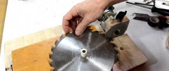
In a home workshop, you can make a simple homemade infrared soldering iron from a car cigarette lighter. The heating element of this device is perfect for making tools.
Since normal operation of the cigarette lighter requires a direct current of 12 Volts, corresponding to the on-board electrical network of the car, you will need an electrical converter so that you can use a household AC network. For these purposes, you can successfully use a power supply for computer cases.
UPD
The files posted above are outdated. In the current version, we have updated the drawings for cutting plexiglass, making a printed circuit board, and also updated the firmware to remove the flickering indicator. Please note that the new firmware version requires CKSEL0, CKSEL2, CKSEL3, SUT0, BOOTSZ0, BOOTSZ1 and SPIEN to be enabled
(that is, change the default settings). Printed circuit board in Sprint Layout V1.1 format Firmware for microcontroller V1.1 File for cutting plexiglass V1.1
This soldering station can also be purchased as a kit for self-assembly in our store and from our partners GOOD-KITS.ru and ROBOTCLASS.ru.