Construction of different types of sewer wells
The sewerage system has a very ancient history, so its design and technology have been brought to perfection. This article will discuss the main issues related to the use of sewer wells in the sewerage system.
The regulatory act regulating the requirements for sewer wells and the procedure for their installation is SNiP 2.04.03-85 “Sewerage. External networks and structures.” The document displays all the factors relating to sewer wells, including their location, classification, size and performance characteristics.
To install a sewer system on a private property, it is necessary to use inspection wells, placing them on the section of the pipeline between the building and the wastewater receiver. In addition, one of the possible options for disposing of wastewater after it has passed through a septic tank is a filter sewer well.
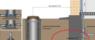
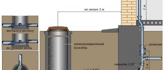
Inspection wells must be installed not only in private households, but also on local sewer systems. The installation site must be located behind the so-called red building line, which is a conditional boundary dividing the target area into certain segments. SNiP states that sewer wells must be installed every 35 meters if the pipeline diameter is up to 150 mm, or every 50 meters for a pipeline with a cross-section of 200 mm.
In addition, inspection wells are installed if the system contains:
- turns and bends;
- changes in pipe diameter or slope;
- branches of the structure.
Requirements for the operational characteristics of reinforced concrete wells are reflected in GOST 2080-90, and for polymer wells - in GOST-R No. 0260760. Most plastic structures are also supplied with manufacturer’s instructions, which outline the conditions for using the well.
Brick, concrete or reinforced concrete are used to make stone sewer wells, and rubble stone is used to create filter wells. Polymer wells can be made of polyvinyl chloride, polypropylene or polyethylene. In addition to structures made from one material, there are structures on the market made from compounds of various materials.
According to SNiP, the dimensions of sewer wells vary as follows:
- when using pipelines with a diameter of up to 150 mm - at least 700 mm;
- up to 600 mm – 1000 mm;
- up to 700 mm – 1250 mm;
- from 800 to 1000 mm – 1500 mm;
- from 1200 – 2000 mm;
- from 1500 mm with a system laying depth of 3 m.
The volume of the structure is not indicated anywhere, but knowing the initial depth and diameter, you can calculate this indicator yourself.
When laying a well, it is necessary to carry out the preparatory work correctly (about
Installation locations
In accordance with the requirements of SNiP, reinforced concrete sewer inspection wells are installed in accordance with the following standards:
- at the junction of side branches of pipelines
- when changing the direction of the pipeline, the diameter of its constituent pipes, or the slope
- on straight sections every 35-300 m, depending on the diameter of the pipeline
Drop structures are installed to change (increase or decrease) flow speed, reduce the depth of sewerage, or at intersections with other communications.
At the same time, regardless of the type of well, the main requirement for it is to ensure reliable protection of the pipeline from mechanical and other damage.
For this purpose, reinforced concrete sewer wells, when installed in traffic areas, are additionally strengthened and, if necessary, equipped with expansion joints. This eliminates the transfer of weight loads to the pipes.
What is a sewer well, for what purposes is it used and what needs to be taken into account when choosing it? These questions are relevant to this day, since without a full-fledged wastewater and waste disposal system, comfortable living in a country house is out of the question.
In order for the external sewage system in a country house or cottage to be efficient and reliable, it must not only be installed correctly, but also selected correctly. In this article we will look at what a sewer well built on the basis of concrete rings is.
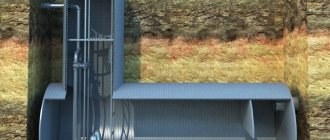
Flooded manhole shaft
The choice of such a design is not accidental, since, despite the fact that polymer and plastic analogues appear on the market, it is the reinforced concrete structure that is installed everywhere outside the city.
Construction of concrete sewer wells
When the preparatory work is completed, the process of installing the well begins.
In the case of a concrete or reinforced concrete structure, the arrangement of a sewer well will look like this:
- first, the base is prepared, for which a monolithic slab or a 100-mm concrete pad is used;
- Next, trays are installed in sewer wells, which must be reinforced with metal mesh;
- the ends of the pipes are sealed with concrete and bitumen;
- the inner surface of the concrete rings must be insulated with bitumen;
- when the tray has hardened sufficiently, you can put the rings of the well itself into it and mount the floor slab, for which cement mortar is used;
- all seams between structural elements must be treated with mortar;
- after grouting with concrete, it is necessary to ensure good waterproofing of the seams;
- the tray is treated with cement plaster;
- in the places where the pipes are connected, a clay lock is installed, which should be 300 mm wider than the outer diameter of the pipeline and 600 mm higher;
- one of the final steps is to check the design for functionality, for which the entire system is completely filled with water. If no leaks appear after 24 hours, then the system is functioning normally;
- then the walls of the well are backfilled, and the whole thing is compacted;
- a blind area 1.5 meters wide is installed around the well;
- all visible seams are treated with bitumen.
How is installation done?
Installation of a cable well takes place in several stages:
- First, a pit is prepared.
It should exceed the dimensions of the well by approximately 200 mm. - Next, a concrete cushion is produced.
Its dimensions depend on the dimensions of the cable well. If the groundwater level is higher than the bottom of the well, the bulk soil should be thoroughly compacted. Finally, an anchor is built from concrete, which will prevent the well from floating. The anchor is made using formwork with a round or rectangular cross-section. If a well is installed where transport passes, a 200-mm reinforced slab is poured, which will make it possible to evenly distribute the load. - The installation of the well itself
is carried out using special equipment, but the work can also be done manually. The structure is attached to anchor bolts and cables. - Carrying out backfilling.
The backfill is a mixture made of sand and cement in a ratio of 1/5. It should be carefully compacted every 20 cm.
Connection to the conduit system can be made using various methods:
- using a sliding coupling with sealing rings;
- using a compression coupling;
- using a sliding coupling with sealing rings.
Communication wells are actively used in buildings of various types. They reliably protect cables from damage and last a long time. Wells of this type are made from various materials, but plastic is most often used. Devices must be built in accordance with a number of technical standards and rules. If you use high-quality materials, do not violate technology and choose the right location, the communication well will serve your home for a long period of time.
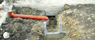
Connecting pipes to wells
Pipes are connected to the well depending on what kind of soil is on the site. In the case of dry soils, the connection is made using cement and asbestos-cement mixture. To install pipes to wells on wet soils, you need to add a resin strand and a waterproofing layer to these materials. These methods are only suitable for arranging the system on non-subsidence soils.
If the soil in the area can shift, then the pipes must be connected movably, for which each of them is wrapped with plastic waterproofing padding. If necessary, you can use a metal sleeve to arrange the packing in its internal space.
Plastic wells for sewerage
Another advantage of plastic wells is the possibility of reducing the size of the viewing window. For example, to replace a concrete well with a meter diameter, it will be enough to install a plastic 30-cm analogue, which is also much easier to maintain. Installing plastic sewer rings is easy and simple.
There are different designs of sewer wells, and the choice of a suitable device depends on the wishes of the owner of the site. We hope that this article helped you understand how a sewer well works and helps you choose the best option.
source
Materials for inspection wells: selection rules
Before proceeding with the installation of the structure, you need to determine what material the sewer tray will be made of. Reinforced concrete and plastic bases are most often used.
Reinforced concrete trays are durable and strong. The disadvantage of the device is its heavy weight and the corresponding difficulties that arise during its delivery and installation.
Plastic bases. They weigh quite little, so they are very easy to install. Plastic shafts are sealed, reliable and durable. They are not prone to deformation due to temperature changes and can easily withstand sub-zero temperatures.
Sewer wells - SNiP, design and installation diagrams
The technology for arranging sewer wells has been worked out to the smallest detail and documented. Construction regulations prescribe a basic series of regulations that the work carried out must comply with. In particular, SNiP has number 2.04.03-85 and is called “Sewerage. External networks and structures.” The document regulates the locations of different types of structures, dimensions and requirements for the structures being erected.
Regardless of the purpose, private or public use, the installation of sewer wells must be carried out in accordance with the rules and requirements. For example, an inspection object must be located in front of the entrance of the local sewerage system to the centralized sewer, outside the red building line.
Current requirements for sewer wells
It is especially important to know that according to SNiP, inspection wells for pipelines with a pipeline size of up to 150 mm are installed every 35 m, and for 200 - every 50 m of direct-flow pipeline sections. In addition, installation of structures is indicated when:
- Rotary changes in the water drainage system;
- When the diameter of the pipeline changes or there is a slope;
- Where additional branches enter.
Documents regulating the requirements: for reinforced concrete products - GOST 2080-90, for polymer structures - GOST-R No. 0260760. Manufacturers offer specifications for plastic structures, supplementing existing regulations.
Stone structures can be made from prefabricated, monolithic concrete, reinforced concrete mixtures, and bricks. The filter structures are made of rubble stone. For the manufacture of polymer structures, it is permissible to use polyvinyl chloride (PVC), polypropylene (PP), and polyethylene of the required density (PE).
Important! Models can be made from a combination of materials.
Distance between inspection wells according to SNiP
It is necessary to install inspection wells in the following situations:
- in the presence of an extended pipeline running in a straight line;
- when there are turns or bends in the pipeline, as well as when the diameter of the pipes changes;
- in the presence of branches of the structure.
SNiP determines the distance between sewer wells, and according to it, the following rules must be followed:
- with a pipe diameter of 150 mm, wells are installed every 35 meters;
- 200-450 mm – 50 m;
- 500-600 mm – 75 m.
As a rule, when arranging private sewer systems, pipes with a diameter of 100 mm are used. When using them, SNiP defines the distance between sewer wells as 15 m. If the sewerage system does not have bends or branches, and the diameter of the pipeline does not change throughout its entire length, then the distance can be increased to 50 m.
Dimensional rulers, work on arrangement of wells
According to SNiP, sewer wells must have the following dimensions:
- Pipelines with a diameter of up to 150 mm - at least 70 mm;
- Diameter up to 600 mm – from 1000 mm;
- Diameter size up to 700 mm – from 1250 mm;
- Diameter 800-100 mm – from 1500 mm;
- With a diameter of 1500 mm and above and a depth of 3 m and above are subject to individual consideration.
Volumes are not separately regulated; everything must be calculated from the depths and diameters specified on the diagrams. As for the work, the general cycle includes preparatory actions, installation and completion.
- Layout or marking of the territory, according to construction rules;
- Clearing the area of bushes and vegetation;
- Demolition/relocation of interfering buildings. The impossibility of action is stipulated by special standards;
- Preparation and arrangement of the entrance and road to the construction site.
Arrangement and installation of a standard sewerage structure, preparatory work according to SNiP:
- Excerpt from the pit;
- Cleaning the bottom;
- Reconciliation with the project in terms of ground level, wall slope angles;
- For stone structures, arrangement of a waterproofing bottom layer, as shown in the diagram or plan (layer of at least 20 cm), subsequent compaction.
All preparatory work has been completed and the next stage is installation.
Stone wells
- Preparation of the base involves laying a slab or arranging a cushion of M-50 concrete 100 mm thick;
- Arrangement of a concrete tray reinforced with steel mesh (M-100) of the required shape;
- Sealing the end holes of the pipeline with concrete and bitumen;
- Creation of an insulating layer of the internal cavity of the rings of the structure;
- Installation of the rings occurs only after the tray has gained strength (2-3 days), then the floor slab is laid. The solution used for work is M-50;
- Sealing joints with cement mixture;
- Waterproofing with bitumen;
- Mandatory plastering of the tray with cement, followed by ironing;
- Installation of clay joints at the entry point of the pipe/pipes with a width of at least 300 mm and a height of 600 mm greater than the diameter of the pipeline.
Subsequent testing work takes place within 24 hours and includes complete filling of the structure with water with the pipeline being blocked with temporary plugs. If no leaks are detected, the well walls are backfilled, a blind area measuring 1.5 m is installed, the joints are insulated with a hot bitumen mixture - the work according to SNiP is completed, the system can be put into operation.
The installation schemes for brick structures are practically the same as concrete ones, but instead of aligning the rings, they are laid out with stone. Waterproofing work is completely identical. In this way, stone wells of any type of sewerage system are installed: domestic, industrial, stormwater or drainage. But each design has its own nuances:
- The storm drain is equipped with lattice hatches that have a drainage function;
- Drainage wells themselves are drainage systems, so installation does not require special calculations.
Construction work order
Before starting work, you need to carefully study the topic and learn how to properly make a sewer well. Primary requirements:
- ensure the specified height of the entry and exit points so that the slope of the pipes complies with the standards;
- the depth of the container should be 50 cm below the soil freezing level (sometimes more);
- the diameter of the working part corresponds to the size of the pipes (up to 160 mm it is 70 cm, over 160 mm the diameter is taken equal to 1 m).
Let's look at how to make a sewer out of a well using concrete rings:
- marking. The outline of the reservoir socket is marked. It is necessary to ensure that the distance to the foundation is maintained (at least 5 m);
- excavation. The soil is removed and either temporarily stored next to the trench or immediately removed;
- At the bottom of the nest, a layer of sand backfill 20 cm thick is placed. The sand is thoroughly compacted;
- install the bottom and carefully level it horizontally. Before installation, the outer part must be covered with a layer of waterproofing;
- install rings. They are placed on top of each other, connected, and the joint line is isolated;
- lay the lid, install the neck;
- connect pipes;
- install thermal insulation, fill the cavity of the nest with soil.
Almost all types of wells are built using this method. The difference between them consists of additional equipment or devices for working with pressure flow, rotating elements, and other parts. The installation process is the same in all cases.
Arrangement of pipeline inlets into the well
Depending on the conditions of a particular location and soil, the entrance parts to the well are designed differently. Installation on dry ground is easier, since it regulates only two types of materials: cement and asbestos-cement mixture. For wet ground, installation requires resin strands and waterproofing materials. But both methods are designed only for soils without subsidence.
On moving soils, SNiP installed movable connections: winding pipes using flexible plastic insulating packing. If you deviate from the rules, you can insert a metal sleeve into the hole in the hatch and install a packing of waterproofing material inside.
SNiP requirements for the dimensions of the blind area in plan and its thickness
The width of the blind area around the house is determined depending on the type of soil subsidence. All clayey (loess) soils are subsident to varying degrees. The type of soil can be determined in laboratory conditions. SNiP 2.02.01–83 approves two types of soils:
“Type I - soil conditions in which subsidence from the soil’s own weight is absent or does not exceed 5 cm; subsidence is possible mainly from external load.
Type II - soil conditions in which, in addition to subsidence of soil from external loads, subsidence from its own weight is possible and its value exceeds 5 cm.”
The same document determines the width of the blind area according to GOST. For soils of the first type, it should not be less than 1.5 m, and for soils of the second type, the width of the blind area should not be less than 2 m.
When building on subsidence soils, it is necessary to take all measures to ensure that the foundation passes through the subsidence layer, plus the use of special construction technologies.
For normally load-bearing soils, regulatory documents determine the minimum width of the blind area to be 0.8–1.0 m. At the same time, its width must necessarily exceed the overhang of the roof above the walls by 20–30 cm.
The thickness (height) of the blind area is to a lesser extent standardized by SNiP. According to regulatory documents, after sampling the soil and plant layer across the entire width of the blind area, a base of clay, sand or crushed stone, at least 15 cm thick, is arranged and compacted. Next, hydro- and thermal insulation layers are laid.
The height of the blind area around the house (mark of the upper protective layer on the outer edge of the blind area) should rise above the “0” mark by at least 5 cm.
If the blind area according to the plan is pedestrian, then the requirements for it from regulatory documents increase in width and strength.