Design of internal water supply and sewerage networks
The internal water supply and sewerage networks of a residential building are designed on plans simultaneously so that the design solutions of the schemes are as simple as possible, easy to use and interconnected. Moreover, priority in design is given to the sewerage system, since during operation it becomes clogged and requires cleaning. It is advisable to use industrial construction methods when designing using sanitary blocks and cabins of various types, but individual installation is also possible.
In the project, deviations from the detailed design are allowed so as not to make two identical floor plans; water supply and sewerage networks are drawn parallel to each other on the same building plan drawing.
When designing, we are guided by the following principles:
- try to lay networks parallel to the walls of buildings and column lines, as straight as possible, so that the length of the pipe is minimal;
- pipelines should not cross beams, columns and other load-bearing parts of the building;
- choose the laying of the cold water supply network taking into account joint installation with other networks (hot water supply, heating);
- network design should begin with the selection of locations for risers for various purposes on floor plans.
We place sewer risers near sanitary fixtures with the most contaminated wastewater, so that they get into the risers through the shortest route, near the main walls, and not near the partitions. In bathrooms, we place sewer risers near the toilet or behind the toilet, in a wall channel or shaft. Sewer risers should not be located near walls adjacent to residential premises.
We lay discharge pipelines from sanitary fixtures along partitions and main walls to the corresponding risers to which they are connected.
We place water risers in places of greatest water intake and take into account the possibility of installing one shut-off valve to disconnect all supply from each riser. Water risers should not be placed on walls adjacent to living rooms or near external walls.
We lay the hearth connections from the water risers along the walls or partitions to the installation sites of the water fittings of the corresponding sanitary fixture.
Water risers can be placed together with sewer risers, leaving holes for them in the ceilings and channels in the walls, taking into account hose lengths of 10, 15, 20 m, and a compact jet height of at least 6 m.
We number all risers clockwise, respectively, water supply: utility and drinking - St.V1-1, St.V1-2, etc., sewer: domestic system - Art. K1-1, St. K1-2, etc.
When placing risers, it is necessary to take into account the layout of the premises so that they are located near walls that allow the fastening of pipelines.
After we have finished designing the networks on the floor plans, we proceed to designing the networks on the basement plan, having first moved all the risers to the same places on the basement plan.
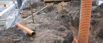
We lay the main water supply pipelines along the shortest distances near the internal walls, columns with a slope of at least 0.002 towards the water metering unit; to drain water from the mudflow and remove air, they connect all risers to the inlet.
We place the domestic sewerage outlets on one side of the building perpendicular to the outer walls.
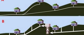
When deciding on the number of outlets from a building, one must proceed from the following conditions:
- best use in the future;
- specific building layout, so that when combining several risers into one outlet, the length of the network is the shortest and with fewer turns, remembering that during operation in places of turns, pipeline clogging is possible.
We install cleanings or inspections in places where the direction of movement of wastewater changes, in straight sections at certain distances. Inspections and cleanings must be installed in places convenient for their maintenance.
Installation of inspections and cleanings on the internal drainage network is carried out similarly to the household sewerage network.
For the installation of cold water supply networks, SNiP 2.04.01-85* recommends using plastic, metal-polymer, fiberglass, steel, cast iron and asbestos-cement pipes. It is allowed to use copper, bronze, brass pipes and fittings for them. In this project we use plastic pipes.
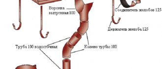
To change the direction of the pipeline, connect side branches, and connect pipes of different diameters, shaped (connecting) parts are used.
We start with installing risers
This is the first stage in the installation process of risers. According to the developed plan, markings are applied to the surface. Only after this they begin to install the pipeline.
The vertical positions of the risers must be observed with maximum rigor. Then there will be no fractures or distortions in the places where the pipes are joined.
The pipes are laid so that the sockets are directed upward. Installation begins, starting work in the basements. At the same time, they are trying to arrange an audit.
What is an audit, why is it needed? This is the name of a type of tee or fitting. It is needed to provide free access to sections of the pipeline where a gap may appear.
They try to install revisions in every place where a corner appears. And also at the beginning, at the end of the sewer.
For a linear and long pipeline, 30 centimeters is the minimum distance between fittings. It is recommended that those who plan to create a wired riser form take care of the inspection hatch. Such hatches are needed to facilitate water supply maintenance.
Ventilation is what each of the sewer risers necessarily ends with. It should go into the attic with good ventilation. Or on the roof of a house.
Toward the end of the duct, the structure looks like a ventilation duct, with a custom build. It is strictly prohibited to route communications into the chimney part of the building; this will not allow compliance with all safety rules.
Horizontal branch lines are installed at the same time as the risers themselves. This applies to every floor of the building.
Bells should not be placed in places where pipes pass through building structures such as floors.
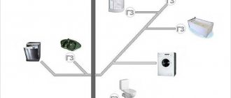
Selecting a water supply system and scheme for the design object
When determining the scheme of water supply networks, it is necessary to take into account that the most economical and simple schemes are obtained in cases where water taps and appliances are grouped and located on the floors of the building one above the other
Structurally, internal water supply networks can be made with upper and lower wiring, dead-end or ring. In residential and public buildings, bottom distribution of main pipes and dead-end networks are most often used.
The section of the network connecting the external and internal water supply systems to the water metering unit is called the inlet. When the external water supply is located parallel to the main facade of the building, the inlet is designed perpendicular to the building, symmetrically to the location of the sanitary fixtures. If there is a hot water supply installation in the building, the inlet should be made into the water heater room, if there is a basement - into the basement, if there is none - into the stairwell or underground channels. In the case where the street water supply pipe runs parallel to the end wall of the building, an input device may be installed through the end wall. The input length should be as short as possible. The input is laid at the depth of the street water supply network with a slope towards the street network.
To measure water flow at the entrances to the building and at the entrances to the apartments, measuring devices are provided - vane or turbine meters (water meters). They can be simple or with a bypass line. Main pipelines, distributing sections of the network and connections to devices are laid with a slope of 0.002....0.005 for draining water.
To water the territory and green spaces around the buildings, watering taps are installed, connected to the internal water pipes of these buildings (one watering tap per 60–70 m around the perimeter of the building.
The choice of internal water supply scheme is made after comparing the value of the specified guaranteed pressure in the city water supply network at the entrance to the building (Hg) with the value of the required pressure (Ntr), determined as a result of hydraulic calculation. The simplest and most common scheme - without installation for increasing pressure and water tanks - is used for round-the-clock water supply from the city network at Нg > Нtr. In the case when the required value of the guaranteed pressure is not provided only at certain hours of the day with insignificant water consumption, it is possible to use a water supply scheme with the installation of a water tank, filled periodically under the influence of an external water supply without boosting devices. To increase the pressure when there is a constant lack of it, it is possible to use local installations: a pumping installation that constantly maintains the required pressure in the system, or a pumping installation operating with a water pressure or hydropneumatic tank.
Fittings and pipes
SNiP clearly states what materials can be used to install internal water supply and sewerage systems:
- For the needs of cold water and hot water supply, pipes and fittings made of polyethylene, polypropylene, polybutene, PVC, fiberglass, as well as metal-polymer, copper, brass, bronze and steel pipes (including those with zinc anti-corrosion coating) can be used;
More details about choosing pipes in the video:
Please note: SNiP recommends laying plastic pipes hidden. Open installation is allowed in places where plumbing fixtures are connected and where mechanical damage to the water supply is prevented.
Installation of polypropylene pipes in grooves eliminates their accidental damage
- For gravity sewerage, cast iron, concrete and reinforced concrete, asbestos-cement, plastic and glass pipes can be used;
- For pressure sewerage, it is recommended to use pressure plastic, concrete, reinforced concrete and asbestos-cement pipes.
In practice, PVC pressure pipes are the most popular
In this case, the material of pipes and fittings must provide:
- One and a half times the safety factor in relation to the operating pressure of the water supply system (but not less than 7 kgf/cm2) at a temperature of 20°C in cold water and 75°C in hot water;
- For hot water supply - resistance to temperatures of at least 90°C at operating network pressure (but not less than 4.5 kgf/cm2);
- The service life is at least 50 years at +20 and operating pressure in cold water and at least 25 years at +75 and operating pressure in hot water.
Here are the requirements for shut-off and control valves for water supply:
- Fittings and fittings for water supply systems must be designed for a working pressure of at least 7 kgf/cm2;
- The design of the fittings must ensure a smooth shut-off of the flow (see Fittings for water supply: types, purpose, selection nuances);
Hint: An instantaneous stop of circulation, or rapid filling of a reset circuit, leads to water hammer. The pressure at the front of the incompressible fluid flow can rise to 25-35 kgf/cm2 for a fraction of a second, which far exceeds the capabilities of polymer and metal-polymer pipes.
The mechanism of water hammer occurrence
- The fittings are installed at the inlet and in individual sections of water supply systems. One system must have at least two independently switchable sections;
- Water supply risers supplying more than three floors are equipped with shut-off valves;
- The same applies to connections that supply more than five water points;
- Shut-off valves are equipped with supply lines for individual apartments, hotel rooms, connections to flush tanks and water heating columns, and outlets for external watering taps.
Ball valves at the cold water and hot water supply inlets to the apartment
Please note: if several DHW risers are connected by a common jumper, shut-off valves are mounted at the bottom and top of each riser.
Residential building plan
The image shows a plan of a residential building that includes outlets of the sewer system, inputs of the heating system, cold and hot water supply with their reference to the angular coordination axes. In addition, it shows the diameters of the outlet and inlet pipelines, and also shows the sewerage wells KK-1, KK-2 and KK-3. According to current codes and standards, the plans must indicate pipe diameters, required elevations and dimensions of sloped pipes, sewer wells and network profiles.
Calculation of water supply networks
The main requirement for the calculation of domestic, industrial and fire-fighting water supply systems is to ensure the standard water pressure in the devices. The calculation is based on the maximum water flow per second. If the system has 2 inputs, then each of them is designed to function fully when the second is disconnected. With multiple injections - 50% fluid consumption.
The standard speed of water movement in a cold water pipeline is 3 m/s. The diameter of the pipes is selected to ensure maximum pressure supplied from the external network. For hot water pipelines, the pressure losses occurring in the supply and circulation lines for each branch of the system should not differ by more than 10%. The diameter of the circulation risers is selected in accordance with the requirements of SNiP.
Attention. Constant water pressure in the pipes, allowing it to flow out of taps, mixers and waste tanks - 2 m,
Axonometric diagrams of sanitary systems
To perform axonometric diagrams of plumbing systems of buildings and structures, frontal isometry with a left-handed axis system is used. This makes it possible to use undistorted measurements on all axes. To designate axonometric diagrams of cold and hot water supply networks, system marks are used, placed directly above the diagrams. Full names of systems are indicated in the relevant specifications.
The figures below show axonometric diagrams of the building's hot and cold water supply pipeline systems. The schematic representation of the water supply system shows shut-off valves, pipe diameters, branches to the risers, places where water drains, as well as pipes for moving from one pipe diameter to another. The level of the first floor is marked using a horizontal line near the risers. In addition, the water supply diagram contains a designation that to arrange its input, pipes with a diameter of 50 millimeters should be used, and the elements should be connected using sockets.
Definitions and general provisions of the document
When designing an internal water supply system, as well as a sewerage system, it is necessary to take into account the established standards. In all buildings connected to the central sewerage system, installation of a water supply and drainage system is provided. Houses that do not have a connection to the central sewer system are equipped with local treatment facilities.
Internal water supply is a utility network that includes pipelines and devices that provide water to one or more buildings.
Internal sewage systems are pipelines and devices that ensure the removal of wastewater from plumbing fixtures. The system is limited to the perimeter of the building and the outlet to the first manhole. The internal sewerage network includes local treatment plants and the removal of storm and melt water.
SNiP water supply and sewerage establishes several important requirements:
- The quality of water for consumers must comply with GOST 2874-82.
- Pipes, shut-off valves and equipment used in the installation of utility networks must comply with the standards determined by the technical conditions and SNiP.
- To transport drinking water, pipes made of materials approved by the Glavsanepidnadzor of the Russian Federation are used.
Plumbing
Sections and sewerage diagrams
Diagrams of risers, as well as sections of sewer systems, show the location of risers and pipelines along branches and risers.
Using the letters A and B on the section that depicts the outlet pipeline next to the KK-1 sewer well, the places where there are branches from the main pipe are indicated. In addition, this section shows data such as pipe diameters, installation locations for inspections, cleanings and other fittings, as well as slopes and lengths of sections. The letters A and B, which are indicated for the sewer risers StK1-1...StK1-3 on the sections, indicate those places where the riser is connected to the main outlet into the sewer well KK-1. The place where the outlet from the sink is connected is indicated by the letter G. The siphon (hydraulic valve), located in front of the P/1 sink, is shown in the section along the outlet from the sink.
The diagrams also contain indications of those places where branches from risers should be laid along the floors to sanitary fixtures. The diagram of the risers of the K1 sewer system (Ø 100) contains instructions for the installation of inspections and the location of branches. To ensure ventilation of the risers, asbestos-cement pipes with a diameter of 150 millimeters are used. They are brought outside through the attic, and weathervanes are used to complete them.
What is a sewer drain pipe, and how does this system work?
First, let's figure out what it is.
A sewer pipe is a section of pipeline that connects the sewerage system to the atmosphere (exits upward through the roof). It branches off from the sewer riser and goes up through the entire house.
At the top (on the roof) it is covered with a fungus (head, umbrella) - so that precipitation and debris do not fall from above.
The waste flows through the sewer pipe from top to bottom. If you open the drain at one point (for example, drain the water in the toilet), then the water will pass through the system without any problems. If water simultaneously drains from several plumbing points (toilet, bathroom sink, bathtub, shower, washing machine), then the riser will be filled to its full diameter.
This will create a vacuum, which will “pull” water out of the water seals, which will cause an unpleasant odor in the bathroom - if there is no drain pipe in the house.
If there is one, then air will be sucked in from the atmosphere through its hole, and the pressure in the system will equalize. Thanks to this, the plumbing seals remain in place and do not allow the smell to penetrate from the pipes into the room.
Another solution to the problem is a fan valve. It can be installed instead of a drain pipe, or it can complement it.
More information about the operation of the sewer system (video)
Why is it needed: purpose and functions
Now let's look at why such a scheme is needed:
- Removing gases that accumulate in the sewer system (they are removed upward through the pipe and released into the atmosphere).
- Maintaining pressure in the sewer system (equalization when draining a large amount of water).
- “Protection” of water seals (preventing them from being sucked in).
In general, the drain pipe ensures the normal operation of the sewer system.
Installation of internal sewerage networks
The internal domestic sewerage network consists of branch lines, risers, and outlets.
Discharge pipelines serve to drain wastewater from receivers through siphons to risers. All drainage lines are laid along the shortest distance with a slope towards the movement of wastewater. The diameters and slopes of branch lines, as a rule, are not calculated, but assigned.
For connecting drain pipes located under the ceiling of a room, in basements and technical undergrounds to risers, as well as for installing branches of drain pipes from bathtubs to one riser at the same level, it is allowed only with the use of oblique crosses. It is not allowed to connect the management of one outlet line of sanitary fixtures located in different apartments on the same floor, as well as the use of straight crosses when located in a horizontal plane. At the beginning of sections of outlet pipes, when there are three or more devices connected, and at turns with an angle of more than 30 degrees, cleaning devices should be installed to remove blockages.
Internal sewer networks can be laid: open along the walls. columns, on special supports in undergrounds, basements, corridors, technical floors, in special rooms intended for placing networks; hidden in furrows, wall niches, installation corridors, sanitary cabins, blocks, panels, under the floor (in channels or ground), sometimes in interfloor ceilings. Branch lines laid between floors must have a length of at least 10 m.
The risers are used to receive wastewater from drainage pipes on all floors. They are placed in areas where the largest number of devices are located and, if possible, closer to those devices from which the most contaminated waste flows (for example, a toilet). The number of risers is reduced if wastewater receivers are concentrated in a group above a group on floors.
The diameter of the sewer riser is selected depending on the estimated liquid flow rate and the largest diameter of the floor pipeline. If there is a toilet, the riser diameter is 100 mm.
If necessary, risers can be installed with indentations or horizontal sections with a slope. Connecting devices to horizontal sections is not allowed. Risers, like branch lines, are laid openly and hidden. The riser at the top ends with an exhaust pipe, which is at least 500 mm higher than the roof of the building. This is necessary for ventilation of the sewer network and prevents the hydraulic valves of wastewater receivers from breaking. At the bottom, the riser ends with a smooth transition into the outlet.
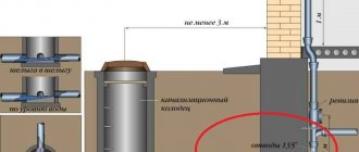
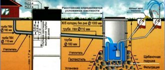
Outlets are designed to receive and drain wastewater from one or more risers into a yard or intra-block network. The risers are connected to the outlet at the beginning of it using two or one 135-degree bends and an oblique tee. Inspection wells are installed at the points where the outlets are connected to the external sewerage system. The length of the outlet from the riser or cleaning to the axis of the inspection well is determined depending on the diameter of the pipes.
Sewer outlets should be located on one side of the building perpendicular to the plane of the external walls from the side of the courtyard facade. For residential buildings with a technical underground or unused basements, it is permissible to install one or two end outlets. The arrangement of enlarged outlets is advisable in cases where a reduction in the length of the external network is achieved. They are not allowed to be installed in houses with operable basements, or in cases where the external sewer network runs along the building. Most often they arrange one release per entrance.
Issues join the external network “shelyga to shelyga. One or two outlets can be connected to each manhole. When determining the minimum depth of outlet from a building, they proceed from the condition of protecting pipes from destruction under the influence of loads and freezing. If the pipelines are deeply buried, when connecting the outlets to the external sewerage network, drops should be arranged: open in the form of concrete spillways, trays (with a drop height of up to 0.3 m). The difference should be arranged in the control well.
The outlet diameter must be no less than the diameter of the connected risers. For residential buildings, the outlet diameter is most often 100 mm.
To make it possible to clean pipes in domestic and industrial sewerage networks, installation of inspections or cleanings is provided. They are installed on risers if there are no indents on them, in the basement or first and upper floors, and if there are indents - above the indents. In residential buildings with a height of more than five floors, inspections are installed at least every three floors. The height from the floor to the center of the revision should be 1 m. Outlets are laid with a slope of at least 0.02 towards the yard sewer network.
Exact recommendations from SNiP for pipe laying
There is the following set of provisions regulated by the document:
- For pipes, the horizontal plane is important. If the direction needs to be changed, special connecting elements are used.
- Branch types of pipelines are attached to risers with tees and crosses.
- An open position of the sewerage system in the basement and in utility rooms is acceptable. Special elements help with mounting on the walls. In the panels and walls of the structure, under the floor, pipes are located only hidden. Then they move on to making hidden furrows.
- Cement-based grout will help seal the areas where the pipes meet the floors.
- It is not allowed to lay drainage lines in the floors, walls or ceilings of living rooms. This also applies to kitchens and any premises where a special sanitary regime is required.
- Hatches are installed on the side opposite from the inspections. Right on the riser.
- Communications for toilets and baths are located above the floor coverings. The main thing is to take care of waterproofing first.