Introduction
The machine consists of three main structural elements:
- base;
- sawing table;
- parallel stop.
The base and the sawing table itself are not very complex structural elements. Their design is obvious and not so complicated. Therefore, in this article we will consider the most complex element - the parallel stop.
So, the rip fence is a moving part of the machine, which is a guide for the workpiece and it is along it that the workpiece moves. Accordingly, the quality of the cut depends on the parallel stop because if the stop is not parallel, then either the workpiece or the saw blade may become jammed.
In addition, the parallel stop of a circular saw must be of a rather rigid structure, since the master makes efforts to press the workpiece against the stop, and if the stop is displaced, this will lead to non-parallelism with the consequences indicated above.
There are various designs of parallel stops depending on the methods of attaching it to the circular table. Here is a table with the characteristics of these options.
| Rip fence design | Advantages and disadvantages |
| Two-point mounting (front and rear) | Advantages: · Quite rigid design, · Allows you to place the stop anywhere on the circular table (to the left or right of the saw blade); · Does not require the massiveness of the guide itself. Disadvantage: · For fastening, the master needs to clamp one end in front of the machine, and also go around the machine and secure the opposite end of the stop. This is very inconvenient when selecting the required position of the stop and with frequent readjustment it is a significant drawback. |
| Single point mounting (front) | Advantages: · Less rigid design than when attaching the stop at two points, · Allows you to place the stop anywhere on the circular table (to the left or right of the saw blade); · To change the position of the stop, it is enough to fix it on one side of the machine, where the master is located during the sawing process. Disadvantage: · The design of the stop must be massive in order to ensure the necessary rigidity of the structure. |
| Fastening in the groove of a circular table | Advantages: · Quick changeover. Disadvantages: · Complexity of design, · Weakening of the circular table structure, · Fixed position from the line of the saw blade, · Quite a complex design for self-production, especially from wood (made only from metal). |
In this article we will examine the option of creating a parallel stop design for a circular saw with one attachment point.
Second design solution
The DIY design solution for a rip fence for a circular saw proposed below is suitable for any workbench: with or without grooves on it. The dimensions proposed in the drawings refer to a specific type of circular saw; they can be proportionally changed depending on the parameters of the table and the brand of the circular saw.
Read also: Vibration support ov 31m characteristics
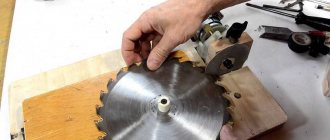
A 700 mm long strip is prepared from the corner indicated at the beginning of the article. At both ends of the angle, at the ends, two holes are drilled for M5 threads. A thread is cut in each hole with a special tool (tap).
In accordance with the drawing below, two guides are made of metal. To do this, take a steel equal angle corner measuring 20x20 mm. They are turned and cut according to the dimensions of the drawing. On the larger strip of each guide, two holes with a diameter of 5 mm are marked and drilled: in the upper part of the guides and one more in the middle of the bottom for an M5 thread. The threads are cut into the threaded holes using a tap.
The guides are ready, and they are attached to both ends with M5x25 bolts with a cylindrical hex head or standard M5x25 bolts with a hex head. M5x25 screws with any head are screwed into the threaded holes of the guides.
Operating procedure:
- loosen the screws in the threaded holes of the end guides;
- the rail moves from the corner to the cut size required for the job;
- By tightening the screws in the threaded holes of the end guides, the selected position is fixed.
The movement of the stop rail occurs along the end planes of the table, perpendicular to the plane of the working saw blade. Guides at the ends of the rip fence angle allow it to be moved without distortion relative to the saw blade.
To visually control the position of the homemade parallel stop, markings are drawn on the plane of the circular table.
To learn how to make a parallel stop for a homemade circular table, see the following video.
It’s hard to imagine a carpentry workshop without a circular saw, since the most basic and common operation is longitudinal sawing of workpieces. How to make a homemade circular saw will be discussed in this article.
Stop ruler is a simple and clear element
This type of tire as a thrust ruler is the simplest, easiest to manufacture and use. When manufacturing it, it is necessary to remember that no matter how simple the design is, it must ensure reliability and safety. A high-quality stop ruler can be used for an electric jigsaw, a hand-held circular saw, or a simple hand saw. Manufacturing is carried out according to the following sequence.
- Prepare a wooden or plywood strip. The width should exceed the width of the platform of the circular saw used by 20 centimeters.
- A ruler is made from this strip. The remaining sheet of plywood is used to make the base.
- The finished structure is screwed to the base. For this purpose, wood screws are used.
- The protruding part of the ruler is carefully trimmed. The edges should be milled.
Stop ruler
When starting to work with a finished tool, it is advisable to carry out several test cuts on secondary wooden products. You need to get used to the fact that when moving the saw along the length of the ruler, you need to apply different forces. Therefore, you should gain some experience. Then proceed to the finishing cut.
What are miter saw stops for?
All kinds of additional devices: stops, clamps, fasteners are used to securely fix the workpieces. The miter saw guide helps you make precise cuts across the grain of the wood. The factory stop has one drawback, which significantly reduces the scope of application. The cut cannot be made larger than the width specified by the manufacturer. This parameter is individual. Cutting boards of greater width requires rigid fastening of the stop.
Circular saw accessories and their purpose
DIY table for a circular saw
Today, a carpenter can both make and buy various products that make his work easier. Additional devices to make working with the saw easier are divided into several types. The main ones are:
- Parallel stop.
- Guide rail for sawing sheet blanks.
- Device for perpendicular cutting and facing.
- Installation bars for precise placement of the guide.
- Adjustable guide for cutting workpieces at a fixed angle.
Using them will significantly reduce time and reduce labor costs when working with massive and large-sized products.
Circular saw stop
First of all, it is necessary for sawing wood products along the grain to a certain width. However, its design has one significant drawback. To ensure safe operation of the saw, it is designed not to come into contact with the guard when working, so cuts cannot be made beyond a certain width. This parameter varies among different saw models and manufacturers.
Before work you must:
- Lock the stop at the desired cutting width.
- Secure the workpiece.
- Press the edge of the fence against the board and guide the saw along the workpiece.
Guide bars for circular saws
The guide bar is a long strip of plywood on which an aluminum u-shaped profile is screwed, which serves as the actual bar along which the saw itself runs directly. The main task is sawing sheet material. The tire is installed on top of the workpiece, aligned along the cutting line. Then it is secured with clamps. When working, the saw should be guided along the guide.
Circular saw blade
It is an aluminum or wooden board with a cut in it for the disk to operate. Attached to the saw base with screws. Used to prevent chipping when cutting plywood or chipboard.
DIY rip fence for a circular saw
It is preferable to make this product from chipboard, since this material is more resistant to wood - in terms of humidity.
The board itself consists of several strips of chipboard or boards, namely four, fastened with self-tapping screws along the entire length along the contour. A semblance of a massive ruler in the form of a box is formed. It is attached to a support board, which ensures its fixation to the tabletop. At the other end there is an eccentric handle. There is a metal runner that ensures smooth sliding of the stop during operation. The stop position is adjusted using bolts that come into direct contact with the table top.
DIY guide bar for a circular saw
It is intended to be used as a stop for the product when cutting. It is a wide board to which a metal corner is attached with screws along its entire length. A saw is placed at the top of this corner of the guide, moving freely along the entire length. Allows smooth cutting of various materials.
DIY ruler for a circular saw
For the ruler you will need several pieces of 12 mm thick plywood, as well as a 20 mm square aluminum profile. A groove is made on the edge of the plywood. The profile along the entire length of the sheet is screwed onto self-tapping screws. The stiffener is screwed to the side using self-tapping screws. Before screwing, the stiffening ribs should be bent slightly to the base of the bending ruler. This is necessary to securely fix the ruler on the part so that it does not “dance.” In addition, a platform is made with a cut-out groove for the guide and for the disk from the same 12 mm thick plywood. It should move freely along the guide.
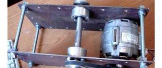
DIY circular saw carriage
To make a carriage with your own hands, we will need a sheet of chipboard. We bolt two metal corners to it - these are guides. We measure a perpendicular from the saw and place a stop for the carriage. In addition to all this, you can make an additional curved groove in the base of the board at 45 degrees for cutting at an angle.
With the help of these auxiliary tools, any carpenter will make his work easier. At the same time, the speed and productivity of labor will increase.
https://youtube.com/watch?v=Ud5lpoe2ehM
Design of a circular saw stop
The entire structure consists of two main parts - longitudinal and transverse (meaning relative to the plane of the saw blade). Each of these parts is rigidly connected to the other and is a complex structure that includes a set of parts.
The main technological solution of this stop is the principle of jamming using an eccentric and tightly pressing two transverse guides with an oblique end.
Fixation occurs by turning the eccentric mechanism.
The pressing force is large enough to ensure the strength of the structure and securely fix the entire rip fence.
The entire design is not trivial and consists of a large number of different parts, each of which has its own purpose and size.
From a different angle.
The general composition of all parts is as follows:
- Transverse part
- The base of the transverse part;
- Upper transverse clamping bar (with an oblique end);
- Lower transverse clamping bar (with an oblique end);
- End (fixing) strip of the transverse part.
- Longitudinal part
- Planar sliding element (laminated chipboard, 2 pcs.);
- The base of the longitudinal part;
- Clamp
- Eccentric
- Eccentric handle
Do-it-yourself circular: drawings, video, description
It’s hard to imagine a carpentry workshop without a circular saw, since the most basic and common operation is longitudinal sawing of workpieces. How to make a homemade circular saw will be discussed in this article.
Preparing for work
Before you begin, you need to decide on the necessary set of tools and materials that will be needed during the work process.
The following tools will be used for work:
During the work you will also need the following materials:
- Chipboard.
- Plywood.
- Solid pine.
- Steel tube with an internal diameter of 6-10 mm.
- Steel rod with an outer diameter of 6-10 mm.
- Two washers with an increased area and an internal diameter of 6-10 mm.
- Self-tapping screws.
- Wood glue.
Design of a circular saw stop
The entire structure consists of two main parts - longitudinal and transverse (meaning relative to the plane of the saw blade). Each of these parts is rigidly connected to the other and is a complex structure that includes a set of parts.
https://www.youtube.com/watch?v=_FBb2k98oz4u0026t=1092s
The main technological solution of this stop is the principle of jamming using an eccentric and tightly pressing two transverse guides with an oblique end.
Fixation occurs by turning the eccentric mechanism.
The pressing force is large enough to ensure the strength of the structure and securely fix the entire rip fence.
The entire design is not trivial and consists of a large number of different parts, each of which has its own purpose and size.
From a different angle.
The general composition of all parts is as follows:
- The base of the transverse part;
- Upper transverse clamping bar (with an oblique end);
- Lower transverse clamping bar (with an oblique end);
- End (fixing) strip of the transverse part.
- Planar sliding element (laminated chipboard, 2 pcs.);
- The base of the longitudinal part;
- Eccentric
- Eccentric handle
Preparation of blanks
It all starts with the fact that it is necessary to cut the workpieces to the specified dimensions.
A couple of points to note:
- flat longitudinal elements are made from laminated chipboard, and not from solid pine, like other parts.
- Two blanks of clamping strips are made with “oblique” ends (not 90º, but 63.5º).
Thus, we get the following set of blanks.
Eccentric clamp
Let's start making an eccentric clamp that rigidly fixes the guide.
We glue two blanks measuring 80x80 mm together.
Press with a clamp and let the glue dry. In the toga you get something like this.
Using a 22 mm feather drill, we drill a hole in the end for the handle.
In the center of the workpiece you need to make a blind (not through) hole 5 mm long.
It is better to do this by drilling, but you can simply hammer it with a nail.
The circular saw used for work uses a homemade movable carriage made of laminated chipboard (or, as an option, you can whip up a false table), which is not too bad to deform or damage. We hammer a nail into this carriage in the marked place and bite off the head.
Thus, we have an improvised axis of rotation for our part, called the “eccentric” (although in this case, the filled hole is located strictly at the geometric center).
Then, putting the workpiece on an axle made of a nail, we begin to grind off the corners and excess material.
As a result, we get a smooth cylindrical workpiece that needs to be processed with a belt or eccentric sander.
We make a handle - it is a cylinder with a diameter of 22 mm and a length of 120-200 mm. Then we glue it into the eccentric.
Transverse part of the guide
Let's start making the transverse part of the guide. It consists, as mentioned above, of the following details:
- The base of the transverse part;
- Upper transverse clamping bar (with an oblique end);
- Lower transverse clamping bar (with an oblique end);
- End (fixing) strip of the transverse part.
Upper transverse clamping bar
Both clamping bars - upper and lower - have one end that is not straight 90º, but inclined (“oblique”) with an angle of 26.5º (to be precise, 63.5º). We have already observed these angles when cutting the workpieces.
The upper transverse clamping bar serves to move along the base and further fix the guide by pressing against the lower transverse clamping bar. It is assembled from two blanks.
They are collected with glue.
And they are additionally fixed with self-tapping screws.
Lower transverse clamping bar
The lower transverse clamping bar is rigidly fixed to the base and serves to fix the guide by pressing against the upper transverse clamping bar.
Like the top bar, it also consists of two blanks.
We also assemble using glue and screws.
Both clamping bars are ready. It is necessary to check the smoothness of the ride and remove all defects that interfere with smooth sliding; in addition, you need to check the tightness of the inclined edges; There should be no gaps or cracks.
With a tight fit, the strength of the connection (fixation of the guide) will be maximum.
Assembling the entire transverse part
The cross guide bar of the cross guide is directly fixed to the circular table.
A transverse base is attached to this bar.
We assemble the entire structure using glue and screws.
Longitudinal part of the guide
The entire longitudinal part consists of:
- Planar sliding element (laminated chipboard, 2 pcs.);
- The base of the longitudinal part.
Planar sliding element
This element is made from laminated chipboard because the surface is laminated and smoother - this reduces friction (improves sliding), and is also denser and stronger - more durable.
At the stage of forming the blanks, we have already sawed them to size, all that remains is to refine the edges. This is done using edge tape.
The technology for edging chipboard is simple (you can even glue it with an iron!) and understandable.
The base of the longitudinal part
The base consists of four longitudinal elements, as well as two vertical ones for installing an eccentric.
If you break it down into details, you get the following diagram.
We collect the previously sawed blanks for glue.
We also additionally fix it with self-tapping screws. Do not forget to maintain a 90º angle between the longitudinal and vertical elements.
Assembly of transverse and longitudinal parts
First you need to attach the substrate (longitudinal element) to the upper transverse clamping bar.
We fix it with glue and screws.
Here it is VERY!!! It is important to maintain an angle of 90º, since the parallelism of the guide with the plane of the saw blade will depend on it.
Then we install the longitudinal base on the substrate.
We also fix it with glue and screws.
Installation of the eccentric
The eccentric is installed between two vertical elements on the longitudinal part.
A metal tube (future bushing) with an internal diameter of 6-10 mm must be placed in the eccentric itself.
We fix it with glue.
In addition to the bushings on the eccentric itself, you need to make similar bushings on the vertical elements, although, as an option (worst), you can use larger washers.
Additionally, a thrust block must be installed for better clamping.
Saddle stop
If you have to saw a lot of identical bars with a circular saw, then it’s worth spending time making a simple saddle stop. Its use will more than return the spent minutes. The saddle stop works especially effectively when cutting thick beams, for which the disk requires two cuts from different sides.
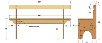
The saddle stop is U-shaped. The base is a board 25 mm thick, its width is exactly equal to the thickness of the sawn timber.
The side surfaces of 10 mm plywood are attached to the base. The width of the sidewalls must be greater than the width of the beam in order to provide support for the circular saw platform until the saw blade comes into contact with the beam.
The saddle is put on the beam at a distance from the cut marking, corresponding to the working distance to the saw blade, and is pressed through the sidewalls to the beam with clamps. Using the side as a support for the saw platform, cutting is carried out. If the thickness of the timber is such that one cut is not enough, then it is turned over and another cut is made. The position of the stop does not change in any way.
Useful tricks and tips
There are such small devices that it is shameful to even consider them a tool. At the same time, they are great for cutting. These are the tricks of experienced masters.
Blank template
When cutting a large number of identical parts, you can use the first of them as a template for cutting subsequent copies. You just need to fasten a thrust piece on one side of the first sample with a width corresponding to the distance from the edge of the slab to the cutting disc. By installing such a template on the material to be cut, you can make many identical parts without markings.
Installation bars
The simplest part that makes it easier to install any stop and guide along the markings is a small cross-section block. There are cuts on it, the distance between which is equal to the segment from the end of the saw sole to the saw blade. Two such bars will help you install any guides quickly and accurately at the required distance from the marking line. All that remains is to secure the guide.
Carriage for circular saw and installation of front and rear stops:
- The additional rail (F) on the carriage, Figure 1, is needed for working with long workpieces. (Note: The rack can be installed on the right side; the T-nuts for the bolts are inserted into the pockets on the inside of the stop.)
- Next, drill through holes in the stop and additional rail, insert the nuts and tighten the bolts.
- Make a cut at the base of the slide, no more than 1/2 of the total length of the carriage, photo C.
- Turn off the saw. Using a square, set the back stop perpendicular to the saw blade, photo C. Secure the stop firmly to the base using clamps.
- Using a wide piece of scrap wood with absolutely parallel sides, make a test cross cut, Photo D. Once cut, turn one of the halves 180 degrees and place its cut against the cut of the other half. The adjustment can be considered complete when there is no gap between the cuts, photo D insert.
- After all the adjustments, it’s time to screw first the back stop (C), and then the front stop (B).
Installing the disc guard and skid stop block:
- Glue and secure the blade guard (E) to the stop (C), photo E.
- For safety reasons, the table carriage should stop the moment the top of the saw blade touches the blade guard, Figure 1.
- Two pieces of wood rigidly fixed to the carriage and to the side of the circular table solve this problem, Figure 1.
- To avoid losing the handles, Photo G, drill holes to match the size of the rubber O-rings on the inner surface of the additional rail, Photo H.
- Make a stop block for the workpiece as shown in Figure 2, it consists of three parts: the front stop block (G), the main stop block (H) and the stop block strip (I). Before gluing the three pieces of the block together, make sure all the faces and edges are square to each other.
- The circular carriage is lubricated with wax at the bottom of the slide and slider, this will allow the carriage to slide smoothly.
The preliminary dimensions of the circular saw carriage are shown in the table below:
How to make a device with your own hands
The cutting device is made for a specific model of power tool. On your circular saw, measure the distance from the engine to the bottom plane of the sole and subtract 5 mm. The result obtained is the height of the guide stop.
Removing the required dimensions of the circular saw.
Prepare a plywood base with right angles and wooden slats with parallel edges according to the dimensions.
Blanks for assembling a device for cross-cutting with a circular saw.
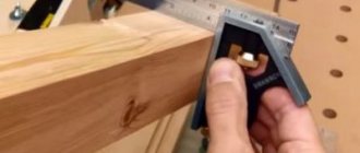
Measure the distance from the cutting blade to the edge of the sole.
Add an allowance of 6–10 mm and install a guide rail at this distance from the right end of the plywood. Secure the plank with countersunk screws, ensuring its strictly perpendicular position.
Screw the stop block on the back side and fix the device on the workbench.
Cut the plywood to the final width with a circular saw, creating a reference edge for precise positioning of the jig along the markings.
Draw a template for the cam clamp cam on paper.
Drawing of an eccentric clamp.
Mark the piece on 10mm plywood and use an awl to mark the center of the drill hole for the bolt.
Cut the workpiece with a jigsaw.
Make a washer with a diameter of 50 mm from the same plywood using a ballerina extendable wood drill.
Sand the workpieces and select an M6 or M8 furniture bolt with a mustache (or with a square headrest), a handwheel nut, a washer and a bushing. The latter can be made from a tube of suitable diameter. The length of the sleeve is the total thickness of the base, lever and plywood washer.
Ready-made plywood eccentric.
Make holes in the base with a drill according to the diameter of the bushing, which serve to rearrange the eccentric clamp according to the width of the board being cut.
Hole drilling diagram.
Assemble the eccentric mechanism: insert a bolt with a sleeve on top, and install a wooden washer, the cam itself and a steel washer from below. Tighten the parts with a nut.
Stick a strip of sandpaper on the inside of the stop to prevent slipping when the eccentric is locked, which can happen when the device is fastened to a smoothly planed workpiece.
The clamping system of this device has a stroke that ensures fastening on boards with a spread of approximately 10 mm in width. If you need to cut or trim pieces of a different size, simply place a wooden block in front of the stop beam.
An example of using a device for cross-cutting a board of smaller width with a hand-held circular saw.
If desired, the potential of the considered device can be expanded by adding a cutting angle of 45°. To do this, you will need to slightly increase the dimensions of the support platform and install a second thrust block at a given angle.
Let's discuss how to work with a hammer drill without dust. And also: disadvantages when using a vacuum cleaner, how to avoid dust when drilling a wall and drilling a ceiling.
The article examines the process of making simple holders, stands and shelves for hand tools in a home workshop.
Options for homemade side stops for a carpentry workbench are considered. A drawing is presented and the manufacturing procedure for one of them is shown in detail.
Master class on replacing a failed nickel-cadmium screwdriver battery with a modern lithium-polymer battery.
Step-by-step instructions with photos examine the process of making a simple tap driver with your own hands.
First execution
A rail is taken from the above-mentioned corner with a length of 450 mm. For correct marking, this workpiece is placed on the working table of the circular saw so that the wide bar is parallel to the cutting saw blade. The narrow bar should be on the desktop on the side opposite the disk, as shown in the figure. In a narrow shelf (41 mm wide) of the corner, at a distance of 20 mm from the end, the centers of three through holes with a diameter of 8 mm are marked, the distances between them should be the same. From the line of location of the marked centers, at a distance of 268 mm, the line of location of the centers of three more through holes with a diameter of 8 mm (with the same distance between them) is marked. This completes the marking.
After this, you can proceed directly to assembly.
- 6 marked holes with a diameter of 8 mm are drilled, and the burrs inevitably created during drilling are processed with a needle file or sandpaper.
- Two 8x18 mm pins are pressed into the outer holes of each triple.
- The resulting structure is placed on the work table in such a way that the pins fit into the grooves provided by the design of the circular saw table, on both sides of the saw blade perpendicular to its plane, the narrow angle bar is located on the plane of the work table. The entire device moves freely on the table surface parallel to the plane of the saw blade; the pins act as guides, preventing the stop from skewing and the violation of the parallelism of the planes of the circular disk and the vertical surface of the stop.
- From the bottom of the work table, M8 bolts are inserted into the grooves and middle holes between the stop pins so that their threaded part fits into the slot of the table and the holes of the rack, and the heads of the bolts rest against the lower surface of the table and are between the pins.
- On each side, over the rail, which is a parallel stop, an M8 wing nut or regular M8 nut is screwed onto an M8 bolt. In this way, rigid fastening of the entire structure to the desktop is achieved.
Operating procedure:
- both wing nuts are released;
- the rack moves to the required distance from the disk;
- fix the rail with nuts.
The rack moves parallel to the working disk, since the pins, acting as guides, prevent distortions of the rip fence relative to the saw blade.
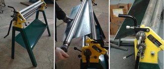
Guide rail
For cutting large and long sheet lumber on the table, a long DIY circular saw guide bar will be useful.
The basis in this case is an (8–10 mm) plywood strip with a length exceeding the dimensions of the sheet being cut. The tire itself can be wooden (a block 15–20 mm thick) or metal from a U-shaped profile. The tire is attached to the base with glue or screws. On one side of it there should be a narrow edge of the base, sufficient for fastening to the sheet with clamps. On the other side, the first cut is made with a saw along the base. After this, the edge of the base will exactly coincide with the passage of the circular disk. When working, it is combined with the markings on the sheet, the stop is secured and the sheet is sawed.
Preparing for work
Before you begin, you need to decide on the necessary set of tools and materials that will be needed during the work process.
The following tools will be used for work:
- A circular saw or you can use a jigsaw.
- Screwdriver.
- Grinding machine.
- Grinder (Angle grinder).
- Jigsaw.
- Hand tools: hammer, pencil, square.
During the work you will also need the following materials:
- Chipboard.
- Plywood.
- Solid pine.
- Steel tube with an internal diameter of 6-10 mm.
- Steel rod with an outer diameter of 6-10 mm.
- Two washers with an increased area and an internal diameter of 6-10 mm.
- Self-tapping screws.
- Wood glue.
Manufactured carriage for a circular saw in parts.
- The size of the base of the slide (A) corresponds to the size of the circular table in the workshop, Figure 1.
- For the back (C) and front stops (B), straight grain, moderately dense wood such as cherry, maple was used. Make sure the stops have absolutely perpendicular edges. The lengths of the stops correspond in size to the width of the base (A).
- As shown in Figure 1, the front and back stops (B) and (C) where the saw blade passes through have a significant increase in stop. Use a band saw or jigsaw to round the sides of the stops to reduce weight and make them easier to handle.
- To make a guide bar (D), use dense hardwood, the size of the bar (runner) corresponds to the size of the groove in the circular table.
- Based on the size of the saw blade, make a protective guard (E), and then round off the near upper corner. (Warning: The guard is not a handle. Do not use it while the slide is moving!)
ASSEMBLY OF BASE, SUPPORTS AND GUIDE.
- Secure the back stop (C) to the base (A). Drill and ream holes in the bottom of the base for flat head screws to adjust the stop later.
- Insert a guide bar (slider) (D) coated with a small layer of glue into the groove of the circular table. Place the base (A) perpendicular to the saw blade on the table and on the guide bar (runner) and leave it until the glue is completely dry.
- Then take some screws and secure the guide bar first to the outside and then to the inside of the slide, as shown in Photo B.
- Turn the base over and check its fit in the grooves on the table, using a scraper or sandpaper if necessary to remove any excess wood on the runner. (Note: You can use a graphite pencil to identify tight areas. Rub the inside edges of the slots on the table with a pencil, then insert the slide into the guide and move it back and forth. The graphite mark on the slider will indicate areas that need trimming.)
From plywood
Necessary materials
To make such a tire you will need three pieces of plywood 10 mm thick. Their length should be the same and is usually equal to the length of the workbench on which the work will be done. One of the segments should be 25-35 cm wide (it will serve as the base), the width of the other two will be determined during the manufacture of the tire. Also prepare 16 mm wood screws.
Drawing with dimensions:
Manufacturing instructions
When creating a guide, all dimensions must be observed very accurately. Small deviations can lead to a sharp deterioration in the result. If desired, laminate can be used instead of plywood.
The plywood guide rail is made in several steps:
- Measure the distance from the inner edge of the saw blade to the rip guide groove located on the tool support platform.
- Cut one of the plywood strips so that its width is 0.2-0.5 mm less than the distance obtained in step 1. The grains of the top layer of veneer on plywood should be directed longitudinally.
- Using self-tapping screws, screw the resulting strip to a wide piece of plywood (base), precisely aligning their ends. This will be the working edge of the tire.
- Using a caliper, measure the width of the longitudinal cut guide groove.
- Screw the remaining strip of plywood to the base parallel to the first strip. There should be a gap between them, the size of which should be 0.2-0.5 mm less than the width of the groove measured in the previous paragraph.
- To avoid damaging the material being cut, a layer of soft fabric is glued to the finished guide on the bottom side.
The homemade guide is ready, all that remains is to prepare the hand saw. To do this, saw off a narrow strip of thick plywood or other sufficiently durable material. The height of this strip should be 8-9 mm greater than the depth of the guide groove on the saw base. The width corresponds to the width of this groove. The length is several centimeters longer than the length of the sole.
The resulting limiter strip should be secured in the guide groove so that it protrudes beyond both edges of the sole.
How to use plywood tire?
To make a cut, you will need two clamps and two flat pieces of wood slightly thicker than the work piece. The guide rail is installed with its ends on these bars so that its working edge protrudes slightly beyond the edge of the workbench table top. In places where the tire rests on the bars, it is tightly fastened with clamps to the workbench.
The workpiece to be cut with a cutting line pre-marked with a pencil is placed under the tire, and the cutting line is aligned with its working edge. Finally, a circular piece with a limit strip attached to it is installed on the tire so that the limiter on the sole fits exactly into the prepared gap. Now you can saw, holding the workpiece with your free hand and lightly pressing the saw towards the workbench.
Nuances when working
In conclusion, here are a few subtleties that are useful to know if you want to make a homemade carriage for a circular saw:
- It is recommended to install a thick block on the supporting wall in the place where the disk passes through it, which will prevent the saw from jumping over the edge of the wall, which can lead to injury.
- In order to give the structure greater slip, it is recommended to clean the runners with sandpaper, and periodically lubricate the grooves with a candle stub (paraffin or stearin). Sometimes wax is used, but it is not recommended to use it, since it melts during use and sticks to the runners.
- Before applying glue to parts, blow the structure away from particles of wood dust and shavings to avoid unevenness after gluing.
- After cutting through the walls, make sure that the saw passes through them freely. To do this, you can make a sawn hole slightly larger than the thickness of the disk.
Having made an end carriage in such a simple way in a home workshop, the craftsman will have at hand an easy-to-use, universal tool that can be used in most types of carpentry work.
Making a workbench
- Mark and cut a tabletop of the required size from plywood. Clean the surface with sandpaper.
- At the bottom of the tabletop we mark places for holes for attaching the saw. To do this, you need to remove the blade and install the saw in the right place, making notes. The holes for the bolts are countersunk on the surface, and the heads of the bolts need to be sanded.
- If the material will be cut at different angles, the hole for the disk should be made in the shape of an inverted trapezoid.
- Mark the places where the stiffening ribs are attached to the tabletop (from below, at a distance of about 8 cm from the edge). The legs need to be secured to the ribs. The ribs are screwed on with self-tapping screws at intervals of 25 cm and glued with PVA.
- The legs are made from timber 100 cm long. Then a screed is made from timber for additional strength.
- To be able to adjust the height of the table legs, nuts and M14 bolts are attached from below.
- We fix the saw from below.
- We attach the socket to the inside of the table. From it we pull the wire to the switch.
- We make a parallel emphasis. We cut two strips of plywood, the same length as the width of the table. The width of the stripes is 10 cm. We make the corners round. We sand both strips and fasten them with self-tapping screws. Then we cut two strips of the same length, but three times wider. We fasten them. This will be the guide. We fasten the stop and guide. We set a right angle relative to the disk. We attach the rollers.
DIY table
To make a table with your own hands, you need to prepare the following devices:
- board;
- your furniture glue;
- ruler;
- a circular saw;
- your pencil;
- electric jigsaw;
- milling machine;
- self-tapping screws;
- sawing tools;
- drilling tool;
- materials for coating the surface with paint.
The table is assembled as follows:
- Create a surface drawing. It is recommended to select larger parameters to make it more convenient to work with the equipment.
- Make countertops. To do this, you need to cut a blank from thick plywood using a jigsaw.
- Process the edges and corners of the tabletop with a router.
- Mark for installation of a circular saw. The workpiece must be turned over and the saw fixed at a certain angle without a disk.
- Try on and adjust the position of the saw. This is necessary in order to install the disk.
- Mark under the stiffening ribs on the inside of the tabletop.
- Make stiffening ribs from boards. Next, you should install them around the perimeter of the workpiece with an indentation of 10 cm from the edge. Use a ruler to mark the center lines and locations of the screws.
- Make through holes according to the marks.
- Make markings for the underground stiffeners and saw them.
- Secure the workpieces to the tabletop with glue, pressing them with clamps from the corner.
- Make and also secure the ribs on the sides.
- Without removing the clamps, fasten the structure using self-tapping screws, placing them in the prepared holes.
- Tighten the stiffening angles together with two self-tapping screws on both sides. Remove the clamps.
- Start making the legs, the height of which should reach 1 meter. To do this, you need to cut the board along the longitudinal axis and make a small angle on one side.
- Secure the lower supports. To make the structure stable, you need to make a screed.
- Install the circular saw into the prepared groove from the inside. Secure its sole with bolts, and insert the disk into the prepared slot.
Important! In addition to assembling the table, you should consider connecting the device to the electrical network. If you have no experience in connecting electrical appliances, it is best to seek help from a specialist.
Ready table
Table saw
When choosing a circular saw, you need to be guided by the following characteristics:
- Saw power. If the amount of work is quite large, it is advisable to take a tool with a power of at least 1.2 kW.
- Cutting depth. The thickness of the material to be processed depends on this parameter. For hand saws it is 40–70 mm. But when installing it in a table there will be a decrease of around 10 mm.
- Button placement. The design of the sawing table must provide free and safe access to all control buttons, otherwise it will be necessary to modify the control system yourself.
- Rotational speed. For cutting wood, high rotation speed is preferred. This affects the cutting quality. For plastic, for example, this is not very good. Due to the high rotation speed of the circle, the plastic heats up. You need to choose average characteristics. 3-4 thousand rpm will be enough.
Circular and rip fence step by step manufacturing:
Step 1: Making the stop.
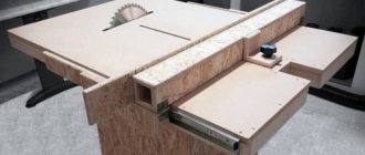
Cut three strips of laminated chipboard 1.1 m long and 8 cm wide, then assemble them together to form a U-shaped profile. Using the internal dimensions of the profile, make five blank inserts for rigidity and insert them inside the profile; they will create the square section required for the stop. The advantage of this stop is that it can be used on both sides of the saw blade (photo on the left).
Step 2: Making a guide channel for the stop.
Step 3: Assembling the Stop - Part 1
So, the circular saw and the rip fence now have a guide channel. Putting it all together, using a small piece of MDF in the shape of an inverted "T", this will be screwed to the back of the stop and inserted into the guide channel. The width of the channel directly depends on the thickness of the T-shaped MDF blank, which will ensure tight placement of the T-shaped piece in the channel.
Step 4: Assembling the Stop - Part 2
Step 5: Stop locking mechanism.
The stop fixation uses slots for the original stop. The locking mechanism is simple: a threaded bolt and nut, a hole in the bottom strip of the rip fence, and a wooden washer. By tightening the bolt, the block pulls the stop down towards the tabletop and clamps it very tightly.
The prize for the most beautiful project does not qualify, but it is made from waste wood and laminate, including bolts and nuts that were not used from factory devices. Changing cut sizes is now quick and much easier than the original fence system. I use the resulting niches in the “pockets” for storing pencils, tape measures, rulers and other necessary tools; as they say, they are “always at hand.”
Making a stop for a circular saw
There are 2 types of cutting stop: parallel and angular. Each option has its own characteristics that you need to know about before manufacturing.
Angular
The angle stop for the machine is used quite often. With its help, boards are cut accurately and quickly at right angles. It is also used for trimming boards from which the stop is made. You can easily make a device for sawing at an angle with your own hands.
- Take a sheet made of plywood for the base. Its thickness should not exceed 1 cm.
- Attach a guide bar to the base, the height of which is no more than 2 cm.
- It is recommended to fix the stop at the bottom, which is perpendicular to the guide. It must be made from the same piece of material.
- Separate unused parts of the bar. The distance from the guide to the saw blade is calculated individually each time, so it is recommended to attach it to the material being processed from the corner with clamps.
- Use fastening devices made of wooden washers.
- Press the wing nut onto the screw.
Edge stop
This is already a rather complex device that requires time and precision in manufacturing. It allows you to cut parallel to the edge of the material being cut. It will be useful to make a drawing of it before starting work so as not to miss the dimensions. Actually, such a stop is included in the circular saw kit, but its short length does not always ensure an even cut. The large size and the desired strength require the base of the stop to be made of plywood with a thickness of at least 15 mm. You can also make a thrust bar from it.
Stages of manufacturing the stop:
- longitudinal grooves for dowels are made at the base;
- hardwood dowels are mounted on a stop bar;
- Another through groove is made between the longitudinal grooves to secure the thrust bar during operation;
- a hole is cut in the base for a circular saw blade;
- On the sides of the base, restrictive strips are placed for installing the circular and clamps are provided to secure it securely.
When installing the stop on the material being processed, the stop bar moves in the grooves of the base to the required distance and is secured through the through slot with a clamping wing screw. In order not to have to worry about the ruler every time, you can attach it (or a piece of tape measure) to the base of the stop along the guide grooves.
Do-it-yourself parallel fence for a circular saw
A regular rip fence for a circular saw is a good example of how a small addition can make a big difference. Almost every hand-held circular saw is equipped with a rip fence for longitudinal cutting of a given width. This is a really useful device.
The standard stop has one drawback. For safety reasons, it is set to values that allow it to be used to make cuts less than 20–25 mm wide.
This is done so that the stop does not interfere with the movement of the saw guard.
But it is enough to attach a wooden block with self-tapping screws to the parallel strip of the standard stop - and its capabilities will increase, while the minimum cutting width will not be limited in any way.
Note! We must remember about safety - when making cuts of less than 15 mm, the block does not allow the protective casing to cover the saw blade.
The simplest option is a cutting stop
The device is actively used when cutting with a jigsaw.
It works quite effectively, but is limited in its suitability for a hand-held circular saw. The tire is pressed against the workpiece using a clamp. The bracket protrudes above the work surface both from below and from above.
As a result, we get restrictions on the length of the cut. The circular motor rests against the clamp, and you have to make the cut in two steps. In this case, the quality of the edge deteriorates and a step may form.
Circular and parallel stop
The circular and parallel stop is perhaps the most important device on a rotary table. Therefore, I decided to take on this project with full responsibility.
I don't spend a lot of time sanding and shaping, no need to fillet the bits, I think cut, glue, secure with screws and a hat case. In my opinion, additional beauty is not always appropriate, and strength is always necessary.
When working with complex projects, I break them down into smaller components and work with them individually. Having a thin aluminum parallel stop at his disposal (photo at right), he had a few inconveniences.
The problem is that for each new cut it is necessary to change the size of the stop, for this, by moving the stop, we take into account the dimensions at the starting point of the workpiece cut and at the point where the saw is cut, then fix it with two handles. It's inconvenient and time consuming.
Circular saw guide
The simplest device is a guide bar. You can easily get a clean, straight cut. For manufacturing you will need an even straight bar of the required length. It is attached to the material being processed using self-tapping screws (if permissible) or clamps.
The fastening must be carried out at such a distance from the required cutting line that the position of the saw blade coincides with the marking when the side sole of the circular saw rests on the block.
This method is suitable for a one-time cut, however, when repeating the same type of operations, the procedure for marking and installing the block will need to be repeated each time.
The guide bar can be improved by securing it to a sheet of durable plywood 6-8 mm thick. When working, one edge of the sheet will align with the cutting line.
At a distance equal to the distance between the saw blade and the edge of the circular saw sole (working distance), a guide block is attached to the plywood with self-tapping screws.
When working, you only need to align the working edge of the plywood sheet with the cutting line and secure the opposite edge with clamps.
The stop ruler is a simple and understandable element
Before we begin to describe the process, we remind you that working with a circular saw is associated with a certain risk, therefore, independent production of accompanying accessories for a circular saw requires strict adherence to safety rules. Now let's return to the cutting fence, which is often used when processing material with an electric jigsaw and can be useful when working with a circular saw, although with some reservations. The thing is that the assembled stop for a circular saw with your own hands is effective in the case of a jigsaw, but with cutting certain inconveniences may arise due to the fact that in this case the tire is pressed to the workpiece with a clamp.
If you are familiar with this type of tool, you can easily imagine how its bracket protrudes from the bottom and top of the machine table top. As a result, we will have a limiter on the length of the cut, but the saw motor will inevitably rest against the clamp, and the cut can only be performed in two stages. Based on such realities, it becomes clear that the quality of the edge will be questionable, and there is a high probability of the formation of a characteristic undesirable step. This is not surprising, because to ensure a perfect cut, continuous movement of the cutting disc is necessary from the beginning to the end of the lumber. Unlike handicraft products, in factory models the fastener is placed outside the line for a circular saw. therefore it does not interfere with comfortable work.
Step-by-step instruction
So, the design details and the necessary tools have been selected, you can begin assembling and subsequent installation of the homemade carriage.
Step 1: Attaching the aluminum profiles
Since the carriage will “run along the saw table,” the first thing to do is guide grooves. To do this, take two U-shaped profiles, approximately equal to the length of the table. You can adjust the dimensions using a grinder.
At the same distance from the location of the cutting disc, circular saws draw two lines parallel to it. Then, using a hand router, U-profile holes are cut out along them, chips are blown out of them, and the corrugated pipes are secured in them using glue. After the glue dries, the grooves are ready.
Step 2: Making the carriage base
Next, the mobile base of the cross-cutting carriage is constructed. To do this, take two strips, which in thickness fit freely into the U-shaped groove. But there is one point here - the carriage will have to “slide” freely on the table, and for this it is raised above the table by 2-3 mm. To do this, nuts of equal thickness are placed into the profile grooves at equal distances, after which guide rails are laid on them.
Then glue is applied to them, which fixes the plywood base strip. To press it tighter, you can attach clamps on the sides.
When the resin has dried, the nuts are removed from the profile grooves and the master checks whether the carriage moves freely on them. After this, for ease of further use, the carriage is cut off on the sides along the table profile.
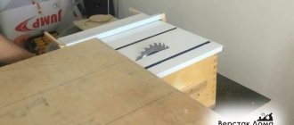
Step 3: Installation of walls
So, the base is ready and then the thrust walls are installed on it. To do this, take two wooden blocks: one of them is rigidly fixed, using self-tapping screws, along the edge closest to the master so that it is strictly perpendicular to the cutting edge of the saw blade; the second is secured along the top edge, but only on one side. This is necessary so that the master can align this wall strictly parallel to the bottom. The operation is performed using a square.
After the walls are leveled, a test cut is carried out. It has two purposes - it is used to saw holes in the walls and base of the carriage, and then by measuring the sawn workpiece, they check whether the right angle of the cut is correct.
Important . The height of the walls must be sufficient so that the cutting edge enters no more than half of it, otherwise the carriage may break during operation - and this is an unjustified risk when working with a circular saw.
Step 4: Making a Combination Square for Miter Cutting
So, a regular straight broach carriage is ready, but what if the cutter needs to cut something at a different angle, such as 60, 40 or 30 degrees? For such operations, you will need an additional structural element, which is called a “combined square”.
The name is put in quotation marks for a reason - the fact is that the base of the workpiece is really a square wooden platform. It is cut out so that it fits freely between the stops of the main carriage and one of the sides is fixed at the bottom wall.