The operating principle of the 380V electromagnetic starter connection diagram
In modern power engineering, electromagnetic starters are widely used.
These are devices designed to repeatedly turn electrical devices on and off.
The task of the device in question is to close and open contacts of electrical circuits of different power, at voltages up to 440 V DC and 600 V AC.
In their design they have:
- a certain set of working contacts designed to supply voltage to the power plant;
- auxiliary contacts - intended for control and signal circuits.
Main differences between starters and contactors
In terms of their design, contactors are similar to starters. They perform the same task, serve the same type of goals. In order not to get confused in this matter, we suggest considering the differences between these devices.
The main distinguishing feature of the contactors is the presence of a powerful arc-extinguishing chamber. As a result, they are used in circuits where high currents are present, and have a much greater weight in relation to the electromagnetic starter.
Accordingly, starters, without arc chutes, are designed primarily for operation where low-power currents flow. Their operating range is up to 10 amperes.
Another design feature of electromagnetic starters is the presence of a plastic case, where the contact pads are brought out. In contrast, most contactors are manufactured without a housing. To isolate from dust, rain, as well as accidental contact with live parts, they are installed in protective boxes or boxes.
Another difference is the purpose of the 380 V electromagnetic starter. Its task is to switch the circuits of three-phase motors. Three pairs of power and one pair of auxiliary contacts are an integral part of this device. The first ones are intended for connecting 3 phases, and the second one serves to supply power to the engine after releasing the “start” button. This operating algorithm is quite common and is suitable for a large number of devices. In this connection, various technical units and devices are connected through these electromagnetic devices.
Let's highlight the main differences :
- compactness;
- design features;
- appointment.
Due to the similarity of functionality and filling, some companies sometimes call electromagnetic starters “small contactors” in their price lists.
Design and principle of operation
The basis of the starter is an inductance coil and a magnetic circuit, consisting of moving and stationary parts. The fixed part is the lower one and is fixed to the body, the upper one is spring-loaded and can move freely.
A coil is mounted at the bottom of the magnetic circuit, and the rating of the contactor changes in direct proportion to its winding. Coils are available from 12 to 380 volts.
As for the upper part of the magnetic circuit, there are movable and fixed groups of contactors.
When there is no power, the springs press out the part of the magnetic circuit located at the top. In this case, the contacts are in the idle or initial state. When voltage is applied, an electromagnetic field is generated in the coil, under the influence of which the upper part of the core is attracted. As a result, the contacts change their position.
When the voltage is removed, the system returns to its original state . The contacts close when voltage is applied and open when it is removed. The electromagnetic starter operates on both direct and alternating currents, the main thing is that the parameters are no more than those specified by the manufacturer.
Magnetic starter device
All types of magnetic starters are united by such design elements as an alternating current electromagnet, a system of moving and fixed power and auxiliary contacts. The supporting part is a body made of heat-resistant and non-flammable plastics. These plastics must be mechanically strong and not deform at elevated temperatures. Any starter is usually three-phase.
The classification of magnetic starters is made according to several criteria, among which the main one is usually the size of the starter. The value does not mean the dimensions or weight of the starter, but what current it can switch and how resistant it is to an arc in circuits with inductances (when the electric motor is turned off). The basis is a non-reversible magnetic starter, since the reversible ones are assembled from the latter. Magnetic starters operate under different conditions, so they are also classified according to the degree of protection: open, protected, dust-splash-proof.
The operation of a magnetic starter very often requires a thermal relay. All types of magnetic starters have structurally compatible thermal relays. They are often produced by the same manufacturer. A particularly important application of thermal relays is to protect electric motors from overheating. The thermal relay consists of two-phase bimetallic conductors (conductors with different coefficients of thermal expansion) - one for each phase.
From an electrical point of view, they are resistors with very low resistance, and thus serve as current sensors. When too much current flows through the phases (or one of them), the bimetallic strip bends and opens the magnetic contacts, that is, the contacts in the starter coil circuit. Thermal relays are connected between the starter and the load.
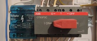
Modular starters are becoming more and more common. These are DIN rail mounted starters. This is a metal profile strip fixed in cabinets on a panel. The simplicity and ease of installation are exceptional. Next to the starter (contactor) you can attach thermal relays, circuit breakers, RCDs (residual current devices), microprocessor controllers and much more. Modular devices are very easy to assemble into circuits, thanks to the wire channels laid between the DIN rails. Installation is carried out with stripped wires of the required cross-section and crimped lugs. The tips are inserted into the holes of the device terminals according to the circuit diagram and clamped with screws.
Electric motor connection diagram 380
We will talk about connecting an asynchronous electric motor when connecting the windings with a star or delta in a 380 V network.
For normal operation of the electric motor, a neutral conductor (N) is not needed, but a protective conductor (PE) is required: it serves to protect the consumer from electric shock when one of the phases breaks down on the housing.
The starter coil is powered through phases L1 and L2. L1 is connected directly, and L2 is connected through the “stop” button - 2, the “start” button - 6, the thermal relay button - 4, which are connected in series to each other.
When you press the “start” button - 6, through the thermal relay button 4, voltage L2 is supplied to coil 5. This is followed by the retraction of the core and the closure of contact group 7 to the load of the electric motor M, as a result of which an electric current corresponding to a voltage of 380 V is supplied.
When the “start” button is turned off, this circuit is not interrupted, and the current passes through the movable block - 3, which closes when the core is retracted. In the event of an accident, thermal relay 1 is activated, contact 4 is broken and the coil is turned off. Return springs return the core to its original position. Voltage is removed from the emergency area when the contact group opens.
Connection diagrams
Let's start by looking at the design of a three-phase electric motor. Here we will be interested in three windings, which create a magnetic field that rotates the motor rotor. That is, this is exactly how the transformation of electrical energy into mechanical energy occurs.
There are two connection schemes:
Let’s immediately make a reservation that a star connection makes the unit start-up smoother. But at the same time, the power of the electric motor will be lower than the rated one by almost 30%. In this regard, the triangle connection wins. The motor connected in this way does not lose power.
But there is one nuance that concerns the current load. This value increases sharply at start-up, which negatively affects the winding. High current in copper wire increases thermal energy, which affects the wire's insulation. This can lead to breakdown of the insulation and failure of the electric motor itself.
I would like to draw your attention to the fact that a large amount of European equipment imported to the vast expanses of Russia is equipped with European electric motors that operate at 400/690 volts. By the way, below is a photo of the nameplate of such a motor.
So, these three-phase electric motors must be connected to the domestic 380V network only in a triangle diagram. If you connect a European motor with a star, it will immediately burn out under load.
Domestic three-phase electric motors are connected to a three-phase network according to a star circuit. Sometimes the connection is made in a triangle; this is done in order to squeeze out the maximum power from the motor, which is necessary for some types of technological equipment.
Manufacturers today offer three-phase electric motors, in the connection box of which the ends of the windings are made in the amount of three or six pieces. If there are three ends, this means that a star connection diagram has already been made inside the motor at the factory.
If there are six ends, then the three-phase motor can be connected to a three-phase network with both a star and a delta. When using a star circuit, it is necessary to connect the three ends of the beginning of the windings in one twist. Connect the other three (opposite) to the phases of the three-phase 380 volt supply network.
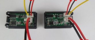
When using a triangle diagram, you need to connect all the ends together in order, that is, in series. The phases are connected to three points connecting the ends of the windings to each other. Below is a photo showing two types of connecting a three-phase motor.
Star-delta circuit
This connection scheme to a three-phase network is used quite rarely. But it exists, so it makes sense to say a few words about it. What is it used for? The whole point of such a connection is based on the position that when starting an electric motor, a star circuit is used, that is, a soft start, and for the main work a triangle is used, that is, the maximum power of the unit is squeezed out.
Similarities and differences between contactors and starters
Both devices serve to close and open the circuit as needed. Their design is based on an electromagnet; they operate on both alternating and direct current. Equipped with power, or main, as well as signal, or auxiliary, contacts.
The difference lies in the degree of protection of the devices. Contactors are equipped with a chamber for extinguishing the arc. Due to this feature, they are used in circuits with higher power than starters. In addition, the device itself is more massive due to arc suppression chambers. The maximum permissible current for starters is up to 10 amperes.
The starters are made in a plastic case and are equipped with eight contacts - six for powering a three-phase motor, and two for providing it with power after the “start” button is stopped pressing. They are used both to power electric motors and devices for which this circuit is suitable.
Contactors are often manufactured without a housing, so during operation it is necessary to provide them with a protective casing that protects it from moisture and contamination, and electric shock to people.
How does a magnetic starter work?
During various switching processes using electromagnetic starters, relays, contactors and other equipment, the electrical resistance in the switching element changes. In these devices, this function is performed by the gap between the contacts. In the closed state, the resistance becomes very small, and as the contacts open, it begins to increase.
Such changes occur very quickly, in an abrupt manner, and are accompanied by a chain break. In some cases, it is necessary to avoid such a break, so non-contact devices are used in such switching circuits. A typical representative of this group is a thyristor contactor, which includes thyristors that have a nonlinear electrical resistance that can change upward or downward.
How does a starter work?
The main parts of the device are an inductive coil and a magnetic circuit, consisting of static and dynamic W-shaped parts. They are located with leads facing one another. The stationary part is fixed to the body, and the movable part is not fixed. At the bottom of the magnetic circuit, an inductance coil is inserted into a special slot.
Depending on its parameters, the nominal operating voltage of the device changes - from 12 to 380 volts. At the top of the magnetic circuit there are two pairs of contacts - static and dynamic.
When there is no power, a spring keeps the contacts open. When power appears, a magnetic field is induced in the coil, and the upper core is attracted to the lower one. As a result, the contacts are closed. After removing the power, the electromagnetic field also disappears, and the spring opens the contacts.
The device can operate from a direct current source, and with single- and three-phase alternating current, the main thing is that its values do not exceed the rating specified by the manufacturer.
220 volt network
When powered from a 220 volt single-phase network, the connection is made through the terminals, which are usually designated A1 and A2. They are located at the top of the starter housing. When a wire with a plug is connected to them, the device is connected to the network. The terminals marked L1, L2, L3 are supplied with any voltage removed from contacts T1, T2 and T3.
When connecting to a device, zero and phase can be easily transferred, this is not important. Typically, power is supplied through a temperature or light level sensor, for example, when connecting the starter to autonomous heating or street lighting.
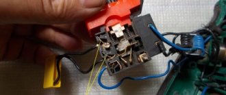
Start and stop buttons
When starting and stopping the engine using a starter, it is convenient to connect a device with buttons connected in series with the device.
To ensure that the engine does not stop working after pressing the “start” button, self-retaining is introduced into the circuit due to the terminals paralleled with the “start”. Thanks to them, the engine runs after the “start” button is no longer pressed, until the stop button is pressed.
Voltage is supplied to the motor through any contact marked with the letter L, and it is removed from the corresponding contact under the letter T. This connection diagram is valid for a single-phase network.
MAGNETIC STARTER CONNECTION DIAGRAM
Before we begin the practical connection of the starter, let us recall a useful theory: the magnetic starter contactor is turned on by a control pulse emanating from pressing the start button, which supplies voltage to the control coil. Keeping the contactor in the on state occurs according to the self-retaining principle - when an additional contact is connected in parallel with the start button, thereby supplying voltage to the coil, as a result of which there is no need to hold the start button pressed.
Disabling the magnetic starter in this case is possible only if the control coil circuit is broken, which makes it obvious that it is necessary to use a button with a break contact. Therefore, the starter control buttons, which are called push-button posts, have two pairs of contacts - normally open (open, normally closed, NO, NO) and normally closed (closed, normally closed, NC, NC)
This universalization of all the buttons of the push-button station was made in order to anticipate possible schemes for providing instant engine reverse. It is generally accepted to call the shutdown button the word: “ Stop ” and mark it in red. The turning button is often called the start button, start button, or is designated by the words “ Start ”, “ Forward ”, “ Back ”.
If the coil is designed to operate from 220 V, then the control circuit switches the neutral. If the operating voltage of the electromagnetic coil is 380 V, then a current flows in the control circuit, “removed” from the other supply terminal of the starter.
Scheme of “self-recovery” magnetic starter
As already mentioned, the previous scheme with two buttons only works if the buttons are latched. In real life it is not used because of its inconvenience and unsafety. Instead, they use a circuit with automatic pickup (self-pickup).
This circuit uses an additional normally open contact of the starter. When you press the “start” button and the magnetic starter is triggered, the additional contact KM1.1 closes simultaneously with the power contacts. Now the “start” button can be released - it will be “picked up” by contact KM1.1.
Pressing the “stop” button will break the coil circuit and at the same time the additional circuit will open. contact KM1.1.
Connection diagram for a 220 V magnetic starter
Here, the current is supplied to the magnetic coil KM 1 through a thermal relay and terminals connected in a chain of buttons SB2 for turning on - “start” and SB1 for stopping - “stop”. When we press “start”, electric current flows to the coil. At the same time, the starter core attracts the armature, resulting in the closure of the moving power contacts, after which voltage is supplied to the load. When “start” is released, the circuit does not open, since the KM1 block contact with closed magnetic contacts is connected parallel to this button. Thanks to this, phase voltage L3 is supplied to the coil. When you press “stop,” the power is turned off, the moving contacts return to their original position, which leads to de-energization of the load. The same processes occur when the thermal relay P operates - a break in the zero N supplying the coil is ensured.
Subtleties of connecting a 220 V device
A DIN rail is used to connect a single-phase magnetic starter and prevent its vibrations. The device must not be placed near rheostats or in a heated part of the box. The tinned end of the conductor connected to the device is bent in the form of a ring or the letter P. A layer of lubricant (technical Vaseline, Tsiatim) is applied to the aluminum cables. The device is turned on according to several schemes.
Classical
Suitable if the load sources are motors or heating elements. The scheme consists of several parts:
- Power. This includes three-phase contacts, an automatic switch (placed between the input and the power source).
- Load. A powerful consumer is required.
- Chain. It consists of a start and stop button, a coil, additional contacts, and is switched to phase and zero.
The starter contacts close and voltage is supplied to the load after pressing the “Start” button. When you press the stop button, the contacts open and voltage is no longer supplied.
Specifics of the power circuit
The single-phase starter is powered through contacts A-1 and A-2. They are supplied with 220 V voltage if the coil is designed for it. The phase is supplied to A-2, the power source is supplied to the elements at the bottom of the housing. Voltage can be supplied from a wind generator, battery, or diesel generator. To remove it, the terminals are used - T-1, T-2, T-3. The downside of the circuit is the need to use a plug to turn the machine on or off.
How to change the control circuit
The power system of the device is not affected during modernization. They work according to the following principle:
- the keys of the push-button station (in one casing) have normally open terminals during startup and normally closed terminals during installation;
- the buttons are placed in front of the magnetic starter in a sequential position - Start and Stop;
- contacts are manipulated using a control pulse;
- the trigger button supplies voltage to the coil and generates a pulse;
- The key is supported using self-locking contacts that supply the coil with voltage;
- The self-locking contacts open, and the coil is self-energized.
The magnetic starter stops after the last circuit is broken.
Connection to a three-phase network
The starter is connected to a three-phase network via a coil that operates from a 220 V network. The signal circuit is not modified. Phase and zero are thrown onto the corresponding contacts. The phase wire is stretched between the start and shutdown buttons. The jumper is installed on normally closed and open elements.
The power circuit is slightly modernized. The phases are supplied to inputs L1, L2, L3, the load is supplied to T1, T2, T3.
This circuit is suitable for an asynchronous motor.
Connection diagram for a 380 V magnetic starter
Connecting to 380 V is practically no different from the first option, the only difference is in the supply voltage of the magnetic coil. In this case, power is provided using two phases L2 and L3, whereas in the first case - L3 and zero.
The diagram shows that the starter coil (5) is powered from phases L1 and L2 at a voltage of 380 V. Phase L1 is connected directly to it, and phase L2 is connected through button 2 “stop”, button 6 “start” and button 4 of the thermal relay, connected in series to each other. The principle of operation of such a circuit is as follows: After pressing the “start” button 6, through the switched on button 4 of the thermal relay, the voltage of phase L2 reaches the coil of the magnetic starter 5. The core is retracted, closing the contact group 7 to a certain load (electric motor M), and current is supplied, voltage 380 V. If the “start” is turned off, the circuit is not interrupted, the current passes through contact 3 - a movable block that closes when the core is retracted.
In the event of an accident, thermal relay 1 must be activated, its contact 4 is broken, the coil is turned off and the return springs bring the core to its original position. The contact group opens, relieving the voltage from the emergency area.
Connecting a magnetic starter via a push-button post
This circuit includes additional start and stop buttons. Both “Stop” buttons are connected in the control circuit in series, and the “Start” buttons are connected in parallel. This connection allows switching with buttons from any position.
Here's another option. The circuit consists of a two-button post “Start” and “Stop” with two pairs of contacts, normally closed and open. Magnetic starter with a control coil for 220 V. The power supply for the buttons is taken from the terminal of the power contacts of the starter, number 1. The voltage approaches the “Stop” button, number 2. It passes through a normally closed contact, along the jumper to the “Start” button, number 3.
Overview of options
In manual mode, activation is carried out from a push-button station. The start button opens the contact to close, and the stop button works to open. The connection diagram for a self-retaining magnetic starter is as follows:
Let's consider the operation of the on and off circuits of a magnetic contactor. A push-button station of two buttons, when you press START, the phase comes from the network through the STOP contacts, the circuit is assembled, the starter retracts and closes the contacts, including the additional NO, which is parallel to the START button. Now, if you release it, the magnetic starter continues to operate until the voltage disappears or the thermal relay P for motor protection is triggered. When STOP is pressed, the circuit is broken, the contactor returns to its original position and the contacts open. Depending on the purpose, the power supply to the coil can be 220V (phase and zero) or 380V (two phases), the operating principle of the control circuits does not change. Switching on a three-phase electric motor with a thermal relay through a push-button station looks like this:
In the end it looks something like this, in the picture:
If you want to connect a three-phase motor through a magnetic starter with a 220-volt coil, you need to make the switch according to the following wiring diagram:
Using three buttons on the control panel, you can organize the reverse rotation of the electric motor.
If you look closely, you can see that it consists of two elements of the previous diagram. When you press START, the KM1 contactor turns on, closing the NO KM1 contacts, becoming self-retaining, and opening the NC KM1, excluding the possibility of turning on the KM2 contactor. When you press the STOP button, the chain is disassembled. Another interesting element of the three-phase reversible connection circuit is the power section.
On the KM2 contactor, phases L1 are replaced by L3, and L3 by L1, thus changing the direction of rotation of the electric motor. In principle, this circuitry for controlling three-phase and single-phase loads completely covers household needs and is easy to understand. You can also connect additional automation elements, protection, limiters. They all need to be considered separately for each specific device.
Using the above diagram for connecting a magnetic starter, you can organize the opening of a garage door by introducing additional limit switches into the circuit, using NC contacts in series with NC KM1 and NC KM2, limiting the movement of the mechanism.
Connecting the motor via starters
Irreversible magnetic starter
If it is not necessary to change the direction of rotation of the engine, then the control circuit uses two non-fixed spring-loaded buttons: one in the normal position is open - “Start”, the other is closed - “Stop”. As a rule, they are manufactured in a single dielectric housing, and one of them is red. Such buttons usually have two pairs of contact groups - one normally open, the other closed. Their type is determined during installation work visually or using a measuring device.
The control circuit wire is connected to the first terminal of the closed contacts of the Stop button. Two wires are connected to the second terminal of this button: one goes to any of the closest open contacts of the “Start” button, the second is connected to the control contact on the magnetic starter, which is open when the coil is turned off. This open contact is connected by a short wire to the controlled terminal of the coil.
The second wire from the “Start” button is connected directly to the terminal of the retractor coil. Thus, two wires must be connected to the controlled “pull-in” terminal – “direct” and “blocking”.
At the same time, the control contact closes and, thanks to the closed “Stop” button, the control action on the retractor coil is fixed. When the Start button is released, the magnetic starter remains closed. Opening the contacts of the “Stop” button causes the electromagnetic coil to be disconnected from the phase or neutral and the electric motor is turned off.
Reversing magnetic starter
To reverse the motor, two magnetic starters and three control buttons are required. Magnetic starters are installed next to each other. For greater clarity, let’s conditionally mark their supply terminals as 1–3–5, and those to which the motor is connected as 2–4–6.
For a reversible control circuit, the starters are connected as follows: terminals 1, 3 and 5 with the corresponding numbers of the adjacent starter. And the “output” contacts are crosswise: 2 from 6, 4 from 4, 6 from 2. The wire feeding the electric motor is connected to three terminals 2, 4, 6 of any starter.
With a cross connection scheme, simultaneous operation of both starters will result in a short circuit. Therefore, the conductor of the “blocking” circuit of each starter must first pass through the closed control contact of the adjacent one, and then through the open one of its own. Then turning on the second starter will cause the first one to turn off and vice versa.
Not two, but three wires are connected to the second terminal of the closed “Stop” button: two “blocking” and one supplying the “Start” button, connected in parallel to each other. With this connection scheme, the “Stop” button turns off any of the connected starters and stops the electric motor.
Typical diagram for connecting a motor via a magnetic starter
This wiring diagram for a three-phase motor should be given the closest attention. It is most common in all industrial equipment produced until about the 2000s. And in new Chinese machines and other simple equipment with 2-3 engines they are still used to this day.
An electrician who does not know it is like a surgeon who cannot distinguish an artery from a vein; as a lawyer who does not know Article 1 of the Constitution of the Russian Federation; like a dancer who does not distinguish a waltz from a tectonic.
In this circuit, three phases go to the motor not through the machine, but through the starter. And the starter is turned on/off using the “ Start ” and “ Stop ” buttons, which can be placed on the control panel through 3 wires of any length.
An example of such a circuit is in the article about restoring the circuit of a hydraulic press, see the last circuit in the article, KM0 starter.
5. Scheme of connecting the motor through a starter with start-stop buttons.
Here, power to the control circuit is supplied from phase L1 (wire 1 ) through a normally closed (NC) “Stop” button (wire 2 ).
Often in such schemes the starter does not turn on due to the fact that the contacts of this button “burn out”.
The diagram does not show a control circuit breaker; it is placed in series with the “Stop” button, the rating is several amperes.
If you now press the “Start” button, the power circuit of the coil of the KM electromagnetic starter will close (wire 3
), its contacts will close, and three phases will go to the motor. But in such schemes, in addition to three “power” contacts, the starter has one more additional contact. It is called a “locking” or “self-latching contact”.
Not to be confused with blocking in reverse circuits, see below.
The “Self-Pickup” contacts are physically located on the same mount with the power contacts of the contactor, and operate simultaneously.
When the electromagnetic starter is turned on by pressing the SB1 “Start” button, the self-retaining contact also closes. And if it is closed, then even if the “Start” button is pressed, the power circuit of the starter coil will still remain closed. And the engine will continue to run until the “Stop” button is pressed.
It often happens in such schemes that the starter does not “self-retain.” It's about that fourth contact.
Installation Tips and Tricks
- Before assembling the circuit, you need to free the working area from the current and check that there is no voltage with a tester.
- Set the core voltage designation which is mentioned on it and not on the starter. It can be 220 or 380 volts. If it is 220 V, phase and zero go to the coil. Voltage marked 380 means different phases. This is an important aspect, because if connected incorrectly, the core may burn out or will not fully start the necessary contactors.
- Starter button (red) You need to take one red “Stop” button with closed contacts and one black or green button with the inscription “Start” with invariably open contacts.
- Please note that power contactors only force or stop the phases, and the zeros that come and go, conductors with grounding are always combined at the terminal block, bypassing the starter. To connect a 220 Volt core to the addition, 0 is taken from the terminal block into the design of the starter organization.
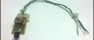
You will also need a useful device - an electrician's tester, which you can easily make yourself.
{SOURCE}