The installation of electronic circuit components is carried out in different ways. One of the most common options is soldering, which ensures reliable contact and strong attachment of parts to the printed circuit board.
It is not very difficult and is accessible even to novice radio amateurs. Soldering SMD LEDs has different features and rules. They are designed to preserve the elements and protect them from overheating. Failure to comply with the requirements leads to the loss of lamps, so it would be useful to consider the issue in more detail.
Basic soldering principles and common mistakes
The process of soldering SMD LEDs consists of applying a thin layer of solder (a low-melting tin-lead alloy with various additives) simultaneously to the contacts of the attached part and the current-carrying tracks of the printed circuit board. Physical processes used:
- wetting of metals with melt;
- capillary impregnation of small gaps between contacts, ensuring connection both mechanically and electrically.
In order to solder SMD diodes, it is necessary to use a special soldering iron with low power and limit the time of contact of the LED device with the hot working part. Experts recommend not to exceed 3-5 seconds. A common mistake is to use soldering irons with a thin tip. This reduces the efficiency of heat transfer and does not allow high-quality heating of the contacts and traces of the printed circuit board.
Experienced people recommend using a normal tip, ground at an angle. The large mass will ensure rapid heating of the pads and melting of the solder, eliminating overheating of the LED. Liquid solder, under the influence of wetting and capillary absorption effects, flows into the smallest gaps between the element legs and the printed circuit board track, after which the hot soldering iron is removed to the side. The solder hardens and creates a monolithic area of strong connection of parts.
The second error leading to LED failure is overheating. Excessively long contact of the soldering iron with the legs of the LED element leads to an increase in the temperature of the emitting crystal. If you do not constantly control the duration of contact of the tip with the part, it will not be possible to avoid excessive heating.
Dismantling SMD parts
So my LED bulb is burned out and I won't fix it. I will solder it into parts for my future homemade products. We disassemble the light bulb and remove the top cap. We take out the board from the base of the base. We unsolder the attached components and parts, wires. In general, there should be a board with only SMD parts. We fix the iron upside down. This must be done firmly so that it does not tip over during the soldering process. Another good thing about using an iron is that it has a regulator that will quite accurately maintain the set temperature of the sole surface. This is a huge plus, since surface components are very afraid of overheating. We set the temperature to about 180 degrees Celsius. This is the second mode for ironing clothes, if my memory serves me correctly. If soldering does not work, gradually increase the temperature. Place the light bulb board on the sole of the inverted iron. We wait 15-20 seconds until the board warms up. At this time, we wet every part with flux. The flux will not cause overheating, it will be a kind of assistant during desoldering. With it, all elements can be removed without difficulty. Once everything has warmed up well, all the parts can be brushed off the board by hitting the board on some surface. But I will do everything carefully. To do this, we will take a wooden stick to hold the board in place and use tweezers to disconnect each component of the board. Bare board at the end of work: Soldered parts:
Factory soldering
In the factory, other soldering technologies are used that allow several boards to be soldered simultaneously. A special robot installs the necessary elements on the base, on the working side of which solder paste is applied using silk-screen printing. It contains solder and flux; when heated, they change phase and perform their tasks. The flux degreases the contacts and provides wetting, and the solder, under the action of capillary effect, flows into the gaps of the connections and ensures a strong connection of the SMD elements.
The process takes place in a special oven, where the board is kept for a certain time. The contact duration and heating mode are selected in such a way as not to harm SMD LEDs. The procedure occurs quite quickly and ensures soldering of elements in industrial quantities.
Important! It will not be possible to repeat this technology at home, since you need to have a full set of equipment and materials. Therefore, it is important for hobbyists to master the process of manual soldering of SMD LEDs using conventional tools and materials.
Description
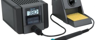
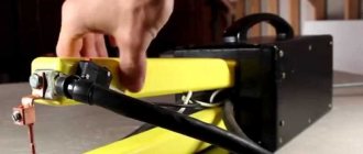
A soldering station differs from a simple network soldering iron in that it has temperature stabilization.
And this is very important when working with various small things. A corded soldering iron always dissipates the same power. That is, if it lies in place, it can even heat up to 500 degrees, and when you start soldering, it cools down sharply. On the other hand, if a thermocouple is built into the soldering iron, then feedback can be organized. This makes it possible to regulate the power on the heater in order to maintain a stable temperature.
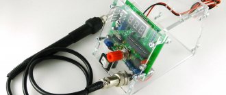
Our goal was to develop a soldering station based on a common and cheap soldering iron with a thermocouple. It has the following characteristics:
- Powered by 12-24V DC voltage source
- Power consumption, when powered 24V: 50W
- Soldering iron resistance: 12ohm
- Time to reach operating mode: 1-2 minutes depending on supply voltage
- Maximum temperature deviation in stabilization mode, no more than 5 degrees
- Control algorithm: PID
- Temperature display on a seven-segment indicator
- Heater type: nichrome
- Temperature sensor type: thermocouple
- Temperature calibration capability
- Setting the temperature using an encoder
- LED to display soldering iron status (heating/operating)
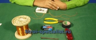
Required materials and tools
To solder SMD LEDs you will need:
- soldering iron with the necessary parameters;
- side cutters, tweezers, scissors;
- mounting needle or thin awl;
- solder and flux. Regular rosin or a special liquid composition, which is an alcohol solution, will do. An aspirin tablet is often used;
- thin brush for applying liquid flux;
- a magnifying glass on an adjustable stand (bracket), which is used by jewelers;
- soldering gun (component of a soldering station).
DIY flux
In tenth place are extreme DIY flux options - a solution of aspirin tablets in cologne, salicylic alcohol, electrolyte from an old salt (non-alkaline) battery, fruit juice, olive oil, ammonia with glycerin, etc. Such fluxes are rarely used for soldering, but you need to know about them. In case you find yourself in a remote village with only a soldering iron in your pocket.
Advantages:
You can make it for free at home from scrap materials.
Flaws:
unpredictable soot and residue with a magical set of active chemical elements.
What to solder : iron, stainless steel, copper, bronze, zinc, nichrome, silver, nickel.
How to wash it off : I have no idea how to wash off cologne mixed with fruit juice and olive oil - it’s probably easier to burn off all the residue with an acetylene torch.
How to solder SMD components
Installation of LED elements is technologically significantly different from connecting a lamp. Soldering SMD LEDs requires some experience and skill. If there are none, it is recommended to first practice on some unnecessary pieces of wire. This will help you master the art of soldering and keep your LEDs in working order. Before starting work, you should inspect the surface of the board. If it is coated with varnish or a layer of silicone, the current-carrying paths to which the LEDs will be soldered should be freed from them.
The specificity of installing SMD LEDs is the absence of conventional long leads. The elements are installed on the board and soldered to the tracks, for which there are small areas on the sides of the LED device housings. The work requires accuracy and attention. It is important to remember the danger of heating, reducing the time the soldering iron touches SMD parts as much as possible. If there is no appropriate tool, a copper wire about 1 mm thick is wound around the tip of a regular soldering iron. One end of this winding serves as a sting, the heating temperature of which is significantly lower than that of the main element. Let's look at the procedure in more detail:
Wiring of planar parts
So, how does the process itself work? Read something here. We bite off small pieces of Rose or Wood solder (alloy). We apply our flux liberally to all contacts of the microcircuit. We put a drop of solder on Rose, on both sides of the microcircuit, where the contacts are located. We turn on the soldering iron and set it using a dimmer, the power is approximately 30-35 watts, I don’t recommend it anymore, there is a risk of overheating the microcircuit during dismantling. We pass the tip of a heated soldering iron along all the legs of the microcircuit, on both sides.
Dismantling using Rose alloy
In this case, the contacts of the microcircuit will close, but this is not scary, after we dismantle the microcircuit, we can easily remove excess solder from the contacts on the board and from the contacts on the microcircuit using the dismantling braid.
So, we took hold of our microcircuit with tweezers, along the edges, where the legs are missing. Typically, the length of the microcircuit, where we hold it with tweezers, allows us to simultaneously move the soldering iron tip between the tips of the tweezers, alternately on both sides of the microcircuit, where the contacts are located, and slightly pull it up with tweezers. Due to the fact that when melting Rose or Wood alloy, which have a very low melting point (about 100 degrees), relative to lead-free solder, and even ordinary POS-61, and moving with the solder on the contacts, it thereby reduces the overall melting temperature of the solder .
Dismantling microcircuits using braid
And thus the microcircuit is dismantled without dangerous overheating. On the board we have the remains of solder, Rose alloy and lead-free, in the form of sticky contacts. To bring the board back to normal, we take the dismantling braid; if the flux is liquid, you can even dip its tip into it, and place it on the solder “snot” that has formed on the board. Then we heat it from above, pressing it with the tip of a soldering iron, and run the braid along the contacts.
Read also: How to weld steel and cast iron using electric welding
Soldering braided radio components
Thus, all the solder from the contacts is absorbed into the braiding, transferred to it, and the contacts on the board are completely cleared of solder. Then the same procedure must be done with all the contacts of the microcircuit, if we are going to solder the microcircuit into another board, or into the same one, for example, after flashing it using a programmer, if it is a Flash memory chip containing the BIOS firmware of a motherboard, or monitor, or what or other technology. This procedure must be performed to clean the microcircuit contacts from excess solder. After this, we apply the flux again, place the microcircuit on the board, position it so that the contacts on the board strictly correspond to the contacts of the microcircuit, and there is still some space left on the contacts on the board, along the edges of the legs. For what purpose are we leaving this place? So that you can lightly touch the contacts with a soldering iron tip and solder them to the board. Then we take a 25-watt EPSN soldering iron, or a similar low-power one, and touch the two legs of the microcircuit located diagonally.
Soldering SMD radio components with a soldering iron
As a result, the microcircuit turns out to be “stuck” and will not budge, since the melted solder on the contact pads will hold the microcircuit. Then we take solder with a diameter of 0.5 mm, with flux inside, bring it to each contact of the microcircuit, and simultaneously touch the tip of the soldering iron tip, the solder, and each contact of the microcircuit. I do not recommend using solder of a larger diameter; there is a risk of adding “snot”. Thus, we have solder “deposited” on each contact. We repeat this procedure with all contacts, and the microcircuit is soldered into place. If you have experience, all these procedures can actually be completed in 15-20 minutes, or even in less time. All we have to do is wash off the remaining flux from the board with solvent 646, or Flux Off cleaning agent, and the board is ready for tests after drying, and this happens very quickly, since the substances used for rinsing are very volatile. 646 solvent, in particular, is based on acetone. Inscriptions, silk-screen printing on the board, and solder mask are not washed off or dissolved.
The only thing is that dismantling a microcircuit in a Soic-16 or more multi-pin package in this way will be problematic due to difficulties with simultaneous heating and a large number of legs. Happy soldering everyone, and fewer overheated microcircuits! Especially for Radio circuits - AKV .
Main conclusions
Soldering SMD LEDs is not very difficult, but requires care and caution. You should remember the danger of overheating of the elements, which will result in their failure. It is necessary to ensure compliance with the following conditions:
- use a low-power soldering iron with a heating temperature no higher than 260°;
- use high-quality flux (experts recommend a special composition for soldering aluminum);
- limit the contact time of LEDs with the soldering iron tip.
In addition, you must remember to maintain polarity and monitor the condition of the current-carrying paths. Please share your options for soldering SMD LEDs in the comments.
Previous
LEDs 12 V step-down transformer: how to choose and connect correctly
Next
LEDs Why and how hot LED lamps get
What is needed for work
Many radio electronics enthusiasts who practice self-assembly of various devices are interested in the possibility of independently soldering LEDs (for example, SMD type) for circuits. If you have the proper tools and knowledge, creating such circuits yourself is quite possible. For this type of work you will need:
- tester;
- calculator;
- medical tweezers (optional, but recommended);
- soldering iron
Note! When working with LEDs, especially when testing them, you need to be careful not to direct the beam coming from these elements into your eyes.
As you can see, the set of tools here is small and can easily be found in any home. With this kit, you will be able to correctly solder diodes, both in the circuit and in series as part of the LED strip.
Microcontroller firmware and first power-up
In the upper left corner of the board there is a standard ISP connector for flashing firmware for AVR microcontrollers.
You can flash the microcontroller with any programmer you have, for example USBasp. If the programmer itself supplies 5V power, then you do not need to connect an external one. You can also find the firmware file itself at the end of the article.
Config bits! CKSEL0, CKSEL2, CKSEL3, SUT0, BOOTSZ0, BOOTSZ1 and SPIEN must be enabled!
That is, it is necessary to change the default settings to run the controller at a clock frequency of 2 MHz.
Now you can connect the soldering iron and apply the input supply voltage (from 12 to 24V). After turning on, the soldering iron should begin to heat up, and the temperature reading on the indicator should increase. When the encoder shaft rotates, the value of the required temperature should change.
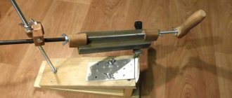
Detailing
The soldering iron handle was made from a jump rope handle. Unfortunately, the handle did not have a through hole, and it had to be drilled. The video shows how this can be done.
The sketch included self-tapping screws as fastening elements for fastening the case and cable, but I didn’t have such small screws at home. So I used hollow rivets that I cut threads into.
I glued the threaded bushings and a spring from a ballpoint pen obtained in this way with epoxy glue into the holes drilled in the pen. If you use self-tapping screws, it is advisable to also drill holes for them so that the handle does not crack.
The frame of the soldering iron is a small tube bent from tin from a tin can. A piece of copper wire with a diameter of 2.5 mm was used as a template for bending the tube. The same wire served as a blank for making a soldering iron tip. When using wire of a different diameter, you will have to make an amendment to the frame development drawing.
The body of the soldering iron is also made of 0.3mm thick tin from a tin can.
In order to ensure the correct shape of the holes and not remove burrs when drilling holes with a diameter of 3 and 4 millimeters, it is better to use drills with zapfenbor sharpening. The holes of the sizes indicated above are necessary to reduce the temperature of the body at the point of its connection with the soldering iron handle. The different diameters of these holes were chosen so that the bending line of the planks did not pass through the holes.
And this is a drawing of the developments: the body, the frame and the contactor. The drawing can be glued to the sheet metal and used as a template for cutting the outline and marking holes. Below the preview is a drawing in A4 format. Drawing scale 1:1, resolution 300 pixels per inch.
PCB installation
When assembling, it is convenient to use assembly drawings:
You need to start by installing SMD components. Install the elements on the boards according to the list of elements. When installing the components, it is important to pay attention to the orientation of the tantalum capacitors and the op-amp. The first pin of DA2 is determined by the bevel on the body.
If everything is assembled correctly, the board should look like this:
Please note that we used 1kΩ resistors without markings. Next, you need to install the output elements on the board in accordance with the list of elements. The long LED lead is a plus. The seven-segment indicator is set with “dots” down.
This is what the front side of the assembled printed circuit board looks like:
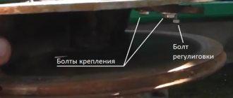
Calibration
A trim resistor is used to finely adjust the temperature. There is a special hole in the front panel for access to it.
When calibrating, first of all it is necessary to bring the tip to the temperature at which the solder melts. You can simply use the encoder to immediately set a very high temperature. Then, having placed a ball of solder on the tip, you need to heat the thermocouple with it. There are special measuring instruments for such purposes, but a regular multimeter with a thermocouple will do. Next, by rotating the trimmer resistor shaft, ensure that the measured value by the soldering station coincides with the readings of the external thermocouple.
When calibrating, remember that the more time you give your soldering iron to stabilize its temperature, the more accurately you will ultimately be able to tune it. Also note that the trimmer is multi-turn and one turn changes the temperature very little. That is, you need to twist it boldly and a lot.
Soldering a transistor with a hairdryer
When repairing household appliances, a home mechanic is often faced with the need to replace electronic components located on circuit boards or mounted using a hinged method.
In this case, you must work carefully, otherwise you can damage the semiconductor layer, burn out the tracks, or even destroy the case.
In order to solder a transistor, microcircuit or diode, you need to know and follow certain installation rules. Read them in this article.
Temperature conditions
All electronic devices are designed to operate at normal temperatures. They cannot withstand overheating for a long time and do not respond well to pulsed temperature influences: the semiconductor junction fails, contacts are broken, and the housing of the radio component is depressurized.
However, the main methods of their installation remain welding or soldering, which ensures the heating of the contact pads and their connection when cooling.
The brands of low-melting solders used, such as POS-60 or POS-40, begin to transform into a liquid state when heated to 183 degrees, and when cooled in air, they quickly cool down and create reliable contact.
The safety of the transistor, diode, microcircuit, capacitor is ensured due to the short time of melting and hardening of the solder on the leg of the radio component.
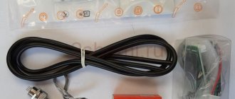
List of components
To assemble the printed circuit board and housing, you will need the following components and materials:
- BQ1. Encoder EC12E24204A8
- C5. Tantalum capacitor 35V, 10uF, size C
- C1-C4, C7-C9. Ceramic capacitors 0.1uF in housing 0805
- C6. Tantalum capacitor 16V, 22uF, size C
- DD1. Microcontroller ATmega8A-AU in TQFP32 package
- DA1. Stabilizer L7805ACD2T-TR 5V in D2PAK package
- DA2. LM358ADT operational amplifier in SO8 package
- HG1. Seven-segment three-digit indicator with a common cathode BC56-12GWA. The board also has a seat for a cheap analogue.
- HL1. Any indicator LED for a current of 20 mA with a pin pitch of 2.54 mm
- R1,R6. Resistors 300 Ohm, housing 0805 - 2 pcs.
- R4, R7-R20. Resistors 1kOhm, housing 0805 - 15 pcs.
- R3. Resistor 100 kOhm, housing 0805
- R5. 1MΩ resistor, housing 0805
- R2. Trimmer resistor 3296W 100kOhm
- VT1. Field effect transistor IRF3205SPBF in D2PAK package
- VT2-VT4. Transistors BC547BTA in SOT323 package - 3 pcs.
- XS2. Terminal for two contacts with pin spacing 5.08 mm
- XS1. Terminal for two contacts with pin spacing 3.81 mm
- XS3. Terminal for three contacts with pin spacing 3.81 mm
- XS4. Programming connector PLS-06
- Soldering iron connector
- Power switch SWR-45 BW(13-KN1-1)
- Soldering iron. We will write about it later
- Plexiglas parts for the body (links to files for cutting plexiglass at the end of the article)
- Encoder knob. You can buy it, or you can print it on a 3D printer. File for downloading the model at the end of the article
- Racks. They can also be printed, but you can use regular sleeves with a 3mm hole and 10mm height
- Screw M3x60 - 4 pcs
- Nut M3 – 8 pcs
- M3 washer - 4 pcs.
- M3 washer enlarged - 8 pcs
- M3 locking washer – 8 pcs
- Assembly will also require installation wires, zip ties and heat shrink tubing.
This is what a set of all the parts looks like:
Completing the build
Now you can screw the board to the front panel. In this case, it is possible to use ordinary racks with a height of 10 mm, but we have prepared special racks that provide better fixation of the board. The 3D printing model can also be found at the end of the article.
The side walls are installed without any fastenings. Now all that remains is to insert the back cover into the grooves, tighten the nuts, pull the power wires through the hole and secure them with cable clamps. Remember that plexiglass parts are quite fragile and do not overtighten the fasteners!