Complete set T12-952
- OLED-STC T12 controller with temperature controller
- Tip heater T12-K
- Soldering iron (black, blue and white color available)
- Silicone cable 1.1 m
- Plug and socket (GX12-4P)
- Black aluminum housing with socket and power switch
- 24 V 4.5 A power supply
- Connecting cables
- A small box of rosin and a few grams of solder.
The heating speed of the T12 tip is very fast, about 6-10 seconds. There are a dozen different tip heaters in stock.
Here's what came in the kit in a neat little package.
This is an aluminum case with an installed switch, socket and fuse.
Switching power supply 24 V 4.5 A.
There are cables, plugs, sockets and some rosin with solder as a gift from the seller.
Optional tip heaters ordered from an available list to choose from.
The STC T12 OLED controller is assembled on the SC92F7462 chip.
Now it's time to assemble according to the instructions.
Individual assembly steps - first the controller. Then the handle, the power supply and finally the controller for the case.
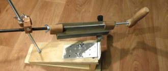
We put it together and here is the first switch on, but without a heater
It remains possible to calibrate the temperature and, of course, work with new equipment.
DIY digital soldering station
About the device: 1. This soldering station is quite popular, as evidenced by the huge amount of information on various resources, where almost all the issues that could arise during the development of the device are discussed. 2. Functionality. In addition to adjusting the temperature, I also wanted to fine-tune the soldering iron, auto-shutdown, and standby mode. 3. Simplicity of the scheme. If you look at each node, you can see that there is nothing complicated in the diagram. All items are common in stores and easily accessible. 4. Information content of the display. No offense to other developers, but I wanted to see on the display not only the temperature of the soldering iron, but also other data, such as the set temperature, the time remaining before switching to standby mode, and others. 5. Cost. I did not compare the cost of the project with other soldering stations, but for me the main thing was not to go beyond a certain amount. I did it. The station in general cost no more than $35. The most expensive parts were the soldering iron, transformer, microcontroller, relay and housing. And if you already have some parts, it’s even cheaper.
Before assembling the soldering station, you need to understand all the elements of the circuit. The list of elements for the circuit is below.
Unfortunately, there was no PCB version for parts in a DIP package, but only for SMD. I don’t like to solder such small parts, but after reading the forum, I realized that sometimes there are problems with such parts (contact - not contact, short circuit, overheating, etc.), and I didn’t have a soldering iron, I still use a regular 25W soldering iron from 220V network. I found a printed circuit board from one user, but redesigned it by more than 50% for myself. On one board I placed an operational amplifier and the control circuit itself with a microcontroller
I left the power part on a separate board: a field-effect transistor, a diode bridge and a relay. If it’s completely Feng Shui, then you need to make all voltage sources on a separate board to avoid interference and interference. That is, +5V, -5.6V is already supplied to the control board. But already as is, and after a month of use I did not notice any problems.
Advertising
10 pcs/lot H11L1M Optocoupler with Schmitt trigger output Reviews: ***Delivered to Ukraine within 40 days. Good quality***
Advertising
Mini MP3 Decoder 5V/12V USB+TF+USB MP3 Player with IR Remote
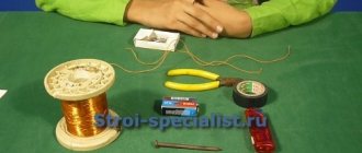
I ordered the display from Aliexpress. This is a regular 2-line display, I ordered 3 pieces with blue backlighting.
The microcontroller used Atmega8L-8. It must be said right away that it doesn’t matter what size the microcontroller is, the main thing is that it has the letter L! I flashed it with a regular usbasp programmer, also bought on aliexpress. There are enough instructions on how to flash a microcontroller on the Internet. Be careful when looking at the programmer pinout. Since the pinout of the programmer itself and the cable for it are different. Look at the photos. For the firmware I used the avrdude program. All hex, eeprom, fuse firmware files are in the archive. Dear Volly has developed several firmware for the station and to its credit, all the firmware is well made and works without glitches so far. I have an operational amplifier for a thermistor. I bought a HAKKO 907 ESD soldering iron with a thermistor. If you have a different soldering iron, then you don’t need to change anything radically. It is necessary to make an operational amplifier specifically for the thermocouple. Everything is visible on the diagram. The operational amplifier is made on an OP07 microcircuit. The power switch based on a field-effect transistor deserves special attention. The original circuit contains IRFZ46N. This is an ordinary fairly powerful field worker. But the problem for such field workers is that if too little voltage is applied to the gate, it does not open completely and begins to get very hot, which is not good. In my case, 3.5-4V was supplied to the gate of the field switch, this turned out to be not enough and it not only warmed up, but boiled. Therefore, I changed the transistor to IRLZ44N. And my 3.5V turned out to be just right. The transistor does not heat up and works properly. I installed the relay that I found on the market. The relay is rated for 12V and can withstand a maximum of 5A and 250V. To control the relay, the diagram indicated a transistor BC879, but I couldn’t find one, so I installed BC547. But in order to know which transistor can be installed, you need to know the relay parameters. Measure or look in the datasheet the resistance of the relay winding, in my case 190 Ohms, the relay winding is designed for a voltage of 12 V, respectively, according to Ohm’s law 12V/190 Ohms = 0.063 A. This means you can simply select an npn transistor with a permissible current of at least 63 mA. On the printed circuit board, the tracks for the relay must be calculated according to yours, which you have.
The transformer is toroidal with two secondary windings: the first is 24V, 3A, the second is 10V, 0.7A. also purchased. I didn't want to shake mine. It’s unlikely that it would have turned out cheaper, and there’s definitely more hassle. When all the parts were ready and soldered, the first thing I did was check the board for snot, short circuits, and undersoldering. Then I plugged it into the network (without a microcontroller) and checked the voltage sources: +5V and -5.6V. Then I checked the operational amplifier. At the amplifier output itself, the voltage should not exceed approximately 2.5V, maybe less. Instead of a soldering iron, I connected a variable resistor and checked how the voltage changes depending on the position of the resistor. After all the maneuvers, I inserted the microcontroller into the panel and turned on the network. Everything worked right away, and the display looked like this:
It was firmware 3.0.7. After that I flashed 3.0.12b. The differences are that the latter has added an auto-shutdown timer and the readings are displayed, some internal improvements and an improved menu. This seems to be the latest firmware for today. I put all this in the case. The Z1W case is black. It is large enough and you could buy, for example, a Z1AW or even smaller. But I decided to “lay” the boards down instead of placing them sideways.
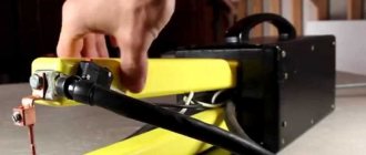
I'm more than pleased with it. All the requirements that I thought about before development were fulfilled. It's been working for over a month now. It should also be noted that the station is turned on by the yellow button on the front panel. But it turns off with a switch on the rear panel. Since the station has a function of complete auto-shutdown from the network, this arrangement suits me for now. But that's it for now. I think in the future, near the yellow button on the front panel, I will put the same one to turn it off, as provided in the circuit. There is also a wire going to the soldering iron stand. It is needed to reset the countdown timer for sleep mode or disconnection from the network. If you set, for example, a timer for 5 minutes and you do not work with the soldering iron (you do not remove it from the stand or do not place it on it), the station will go into standby mode. As soon as you remove the soldering iron from the stand, the timer will immediately reset to 5 minutes (which you set) and begin counting down again. For me, this is a very useful feature. The soldering iron will not heat up all night if you suddenly forget about it. The archive contains all the files, photos, printed circuit boards, firmware, diagram, parts list, instructions. The station is quite easy to repeat. The main thing is to be careful and not to confuse anything.
Archive with printed circuit boards and firmware
Parts list
Soldering iron HAKKO 907 Microcontroller ATMEGA 8L Operational amplifier OP07 IC LM7805 Toroidal transformer Housing Z1W Soldering iron stand Boozer with generator Relay Bicolor diode Display 1602 HD44780 ResistorsTrimmer 5K Trimmer 10K Trimmer 22K 22K 0.25W 10K 0.25W 3k3 0.25W 1k8 0.25W 560 0.25W 470 0.25W
Advertising
5 pieces. OPA2134PA, High efficiency, 2 channel audio amplifier, 0.00008%, 8MHz, 120dB, ±2.5V…±18V,
Advertising
Charging Module TP4056, Micro USB, 5 V, 1 A, for lithium + boost converter MT3608, 2 A Reviews: ***Everything is ok, I soldered the kit the next day, it works in a multimeter from an old phone battery!!!** *
150 0.25W 33 0.25W 39 0.25W Capacitors
Electrolytic 1000 uF*20V Electrolytic 10uF*10V Ceramic 220 Nf Ceramic 100 Nf Ceramic 470 Nf Ceramic 10 Nf
Diodes
Diode bridge RS607 1N4007 Zener diode 5 V6 0.5W Zener diode TL431
Transistors
IRLZ44N BC547
Other
Momentary buttons Switch Fuse Fuse holder Microcontroller holder
Author of modifications and PP Taras
UPD
The files posted above are outdated. In the current version, we have updated the drawings for cutting plexiglass, making a printed circuit board, and also updated the firmware to remove the flickering indicator. Please note that the new firmware version requires CKSEL0, CKSEL2, CKSEL3, SUT0, BOOTSZ0, BOOTSZ1 and SPIEN to be enabled
(that is, change the default settings). Printed circuit board in Sprint Layout V1.1 format Firmware for microcontroller V1.1 File for cutting plexiglass V1.1
This soldering station can also be purchased as a kit for self-assembly in our store and from our partners GOOD-KITS.ru and ROBOTCLASS.ru.
Characteristics and operating principle
Induction soldering station
You can consider the characteristics of soldering stations by dividing soldering methods into two groups: lead and lead-free.
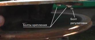
Devices belonging to the first group have a module in their structure that makes it possible to set the required temperature level of the tip. Such models are made both as devices that use electricity for their operation, and as stations based on an alternating magnetic field (induction type). A high level of heat transfer and automatic selection of power for individual elements are the main advantages of induction stations.
To perform non-contact soldering, the second type of soldering installations is used. These are stations based on infrared and thermal air influence on the soldering area.
Summarizing the characteristics of the devices, the following parameters are distinguished:
- heating element material: nichrome or ceramic;
- heating rate;
- temperature adjustment range;
- installation power;
- supply voltage.
Also, the main design features include shape, dimensions and weight.
Why make a station yourself
There are several reasons why stations on the market are not trustworthy: you can never know for sure that you have purchased a good product until it goes through a full test drive; until you disassemble the station to see and evaluate the filling and build quality; and finally, you cannot communicate with other owners of the same model to share impressions and discuss the pros and cons of the station due to the fact that many companies release their products to the market under new brands every couple of years.
A couple of years ago I purchased a soldering station online, and although it still works well, I got tired of working with it due to the stupid design (short power cord, non-compressor airflow and short, non-detachable tip cord). Due to shortcomings in the design, it is inconvenient to rearrange this station even on the table; the body rotates after the sting. The inside was filled with hot glue; a week was spent just cleaning the components and eliminating minor and major defects.
The fastening of the cord of the soldering iron stand was kept on parole, the insulation was constantly knocked down, and this would lead to a break in the wire and a possible fire.